Language selection

Search

Patent 2453789 Summary

Third-party information liability

Some of the information on this Web page has been provided by external sources. The Government of Canada is not responsible for the accuracy, reliability or currency of the information supplied by external sources. Users wishing to rely upon this information should consult directly with the source of the information. Content provided by external sources is not subject to official languages, privacy and accessibility requirements.

Claims and Abstract availability

Any discrepancies in the text and image of the Claims and Abstract are due to differing posting times. Text of the Claims and Abstract are posted:

  • At the time the application is open to public inspection;
  • At the time of issue of the patent (grant).
(12) Patent: (11) CA 2453789
(54) English Title: FUEL PUMP ASSEMBLY FOR VEHICLE
(54) French Title: POMPE A ESSENCE POUR VEHICULE
Status: Deemed expired
Bibliographic Data
(51) International Patent Classification (IPC):
  • F02M 37/10 (2006.01)
  • F02M 37/50 (2019.01)
(72) Inventors :
  • LEE, SUNG WON (Republic of Korea)
(73) Owners :
  • KIA MOTORS CORPORATION (Not Available)
  • HYUNDAI MOTOR COMPANY (Not Available)
(71) Applicants :
  • KIA MOTORS CORPORATION (Republic of Korea)
  • HYUNDAI MOTOR COMPANY (Republic of Korea)
(74) Agent: RICHES, MCKENZIE & HERBERT LLP
(74) Associate agent:
(45) Issued: 2007-02-13
(22) Filed Date: 2003-12-22
(41) Open to Public Inspection: 2005-03-19
Examination requested: 2003-12-22
Availability of licence: N/A
(25) Language of filing: English

Patent Cooperation Treaty (PCT): No

(30) Application Priority Data:
Application No. Country/Territory Date
10-2003-0065260 Republic of Korea 2003-09-19

Abstracts

English Abstract

A fuel pump assembly mounted in a fuel tank for sending fuel to a fuel injector according to this invention includes a driving means for supplying a driving force for sending or returning fuel; a reservoir for temporarily reserving fuel from the fuel tank through a check valve mounted on a bottom portion thereof; a first fuel sucker for sucking fuel reserved in the reservoir; a return pipe for returning fuel from the fuel injector to the reservoir; a second fuel sucker for sucking fuel stored in the fuel tank; and a Z-nozzle portion of which an outlet is connected to a bottom portion of the reservoir, wherein the second fuel sucker and a return pipe is connected to an inlet of the Z-nozzle portion.


French Abstract

Une pompe à essence montée dans un réservoir afin d'envoyer le carburant dans un injecteur de carburant selon cette invention comprend un mécanisme d'entraînement permettant de fournir une force motrice pour l'envoi et le retour du carburant; un réservoir pour retenir temporairement le carburant arrivant du réservoir par un clapet de retenue monté sur la partie inférieure de celui-ci; une première conduite d'aspiration de carburant permettant d'aspirer le carburant retenu dans le réservoir; une conduite de retour permettant de ramener le carburant de l'injecteur de carburant au réservoir; une seconde conduite d'aspiration de carburant permettant d'aspirer le carburant contenu dans le réservoir; et une partie de buse en forme de Z dont une sortie est raccordée à la partie inférieure du réservoir, tandis que la seconde conduite d'aspiration de carburant et une conduite de retour sont raccordées à une entrée de la partie de buse en forme de Z.

Claims

Note: Claims are shown in the official language in which they were submitted.


WHAT IS CLAIMED IS:

1. A fuel pump assembly mounted in a fuel tank for sending fuel to fuel
injector,
comprising:

a driving means for supplying a driving force for sending or returning fuel;

a reservoir for temporarily reserving fuel from the fuel tank through a check
valve mounted on a bottom portion thereof;

a first fuel suction device for sucking fuel reserved in the reservoir;

a return pipe for returning fuel from the fuel injector to the reservoir;

a second fuel suction device for sucking fuel stored in the fuel tank;

a jet pump portion of which an outlet is connected to a bottom portion of the
reservoir,

wherein the second fuel suction device and a return pipe are connected to
an inlet of the jet pump portion, and

the second fuel suction device extends horizontally and outwardly from the
jet pump portion with respect to the fuel tank.

2. The fuel pump assembly of claim 1, wherein the return pipe functions as an
orifice such that the fuel in the fuel tank is sucked into the reservoir
through the
second fuel suction device.

3. The fuel pump assembly of claim 2, wherein one end of the return pipe,
which is connected to the jet pump portion, is banded to the direction of the
reservoir.

4. The fuel pump assembly of claim 2, wherein a first detent is formed on the
bottom portion of the reservoir and a hook is formed on the jet pump portion
such


8


that the jet pump portion is fixed to the reservoir by a connection between
the first
detent and the hook.

5. The fuel pump assembly of claim 4, wherein a hole is formed on the second
fuel suction device and a second detent is formed on the jet pump portion such
that
the second fuel suction device is fixed to the jet pump portion by connection
between the second detent and the hole.

6. The fuel pump assembly of claim 5, wherein the connection between the
second fuel suction device and the jet pump portion is sealed with thermal
fusion.


9

Description

Note: Descriptions are shown in the official language in which they were submitted.


CA 02453789 2003-12-22
TITLE OF THE INIiEN'1'fOl~
I=UFL PUMP ASSEIViBL~ F~~ \IEHICLE
~ACKta1~0U1V~ OF THE IN~ETIO
(a~ Field ~f the Invention
This invention relates to a fuel pump assembly mounted in a fuel tank for
sending fue! stored in the fuel tank to a fuel injector, and more
particularly, to a
fuel pump assembly for stably sending fuel to a fuel injector when the fuel is
driven to the corner of the fuel tank.
(b) ~escritiorl of the Related Art
Generally, a fuel pump assembly mounted in a fuel tank storing fuel
comprises a fuel pump for sending fuel from the fuel tank to a fuel injector
and
returning fuel from the fuel injector to the fuel tank, and a reservoir
mounted in
the fuel tank for temporarily reserving fuel.
However, when a vehicle moves on an inclined road or a curved road,
the fuel reserved in the fuel tank is driven to a corner of the fue! tank such
that an
additional fuel sucker driven by the fuel pump should be provided.
Accordingly, due to the additions! sucker and a connecting means for
connecting the fuel sucker and the fuel tank assembly, the inner structure of
the

CA 02453789 2003-12-22
fuel tank become complicated such that it is difficult 1(o assemble the fue(
tank
assembly.
~UIIIIIUIAY ~F 'THE I~fEN~'I~IV
The motivation for the present invention is to solve the above problems,
and accordingly to provide a fuel pump assembly having non-limiting
advantages of stable fuel supplying to the fuel injector with a simple
structure for
the case in which the fuel is driven to the corner of the fuel tank.
An exemplary fuel pump assembly mounted in a fuel tank for sending fuel to a
fuel injector according to this invention includes a driving means for
supplying a
1o driving force for sending or returning fuel; a reservoir for temporarily
reserving
fuel from the fuel tank through a check valve mountee~ on the bottom portion
thereof; a first fuel sucker for sucking fuel reserved in the reservoir; a
return pipe
for returning fuel from the fuel injector to the reservoir; a second fuel
sucker for
sucking fuel stored in the fuel tank; and a Z-nozzle portion of which an
outlet is
connected to a bottom portion of the reservoir, wherein the second fuel sucker
and a return pipe are connected to an inlet of the Z-nozzle portion.
Preferably, the second fuel sucker horizontally extends with respect to the
fuel
z

CA 02453789 2006-08-31
tank.
Preferably, the return pipe functions as an orifice such that the fuel in the
fuel tank is sucked into the reservoir through the second fuel sucker.
Preferably, one end of the return pipe, which is connected to the Z-nozzle
portion, is bended to the direction of the reservoir.
Preferably, a first detent is formed on the bottom portion of the reservoir
and a hook is formed on the Z-nozzle portion such that the Z-nozzle portion is
fixed to the reservoir by a connection between the first detent and the hook.
Preferably, a hole is formed on the second fuel sucker and a second
detent it formed on the Z-nozzle portion such that the second fuel sucker is
fixed
to the Z-nozzle portion by connection befinreen the second detent and the
hole.
Preferably, the connection between the second fuel sucker and the Z-
nozzle portion is sealed with thermal fusion.
In another aspect, the present invention resides in a fuel pump assembly
mounted in a fuel tank for sending fuel to fuel injector, comprising: a
driving
means for supplying a driving force for sending or returning fuel; a reservoir
for
temporarily reserving fuel from the fuel tank through a check valve mounted on
a
bottom portion thereof; a first fuel suction device for sucking fuel reserved
in the
reservoir; a return pipe for returning fuel from the fuel injector to the
reservoir; a
second fuel suction device for sucking fuel stored in the fuel tank; a jet
pump
portion of which an outlet is connected to a bottom portion of the reservoir,
wherein the second fuel suction device and a return pipe are connected to an
inlet of the jet pump portion, and the second fuel suction device extends
horizontally and out~niardly from the jet pump portion with respect to the
fuel tank.
3

CA 02453789 2006-08-31
BRIEF DESCRIPTION OF THE DRAWINGS
The accompanying drawings, which are incorporated in and constitute a
part of the specification, illustrates an embodiment of the invention, and
together
with the specification, serve to explain the principals of the invention.
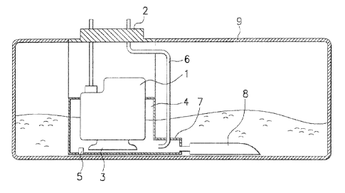
FIG. 1 is sectional view of a fuel pump assembly according to an
3a

CA 02453789 2003-12-22
embodiment of this invention.
FI~. 2 illustrates a connection between a ~-nozzle portion and a
reservoir.
Fly. 3 illustrates a fuel flow in the ~-nozzle por~:ion.
~ETAI~E~ ~ESCRIP'Tr~N F Tt~E ~RE~ERRE~ E~~~IiIAEN'fS
An embodiment of the present invention will hereinafter be described in
detail with reference to the accompanying drawings.
FI~. 1 is a sectional view of a fuel pump as~ernbfy according to an
embodiment of this invention.
1o As shown in FICA. 1, the fuel pump assembly 2 includes a driving means 1, a
reservoir 4 mounted in a fuel tank 9, a first fuel sucker ~ for sucking fuel
in the
reservoir 4, a return pipe 6 for returning fuel, a second fuel sccker ~ for
sucking
fuel stored in the fuel tank 9, and a ~-nozzle portion 7 mounted to the
reservoir
4.
~5 The reservoir ~ receives the driving means 1 and the first fuel sucker 3
therein,
and a check valve ~ is mounted on the bottam surface of the reservoir 4 such
that fuel in the fuel tank 9 is supplied to the reservoir 4 tl~rou~gll the
check valve
5.

CA 02453789 2003-12-22
Furthermore, the fueE from a fuel injector (not shown) is returned to the
reservoir 4 through the return pipe ~.
The fuel temporarily reserved in the reservoir is sent to the fueE injector
by the driving force generated by the driving means 1.
Meanwhile, the Z-nozzle portion is connected to the side of the reservoir
4.
An inEet of the Z-nozzle portion is connected to the return pipe ~ and the
second fuel sucker ~, and the outlet of the Z-nozzle po~E~tion is connected to
the
reservoir 4.
1o FIG. 2 ilEustrates a connection between a Z-nozzle portion and a
reservoir.
As shown in FIG. 2, a first detent 1 g is formed on the reservoir ~ and a
hook ~ 1 is formed on the Z-r~ozzEe portion 7. The first decent 1a and the
hook 11
are compEementarily combined such that the Z-nozzle portion 7 is fixed to the
reservoir 4.
Furthermore, a second decent 12 is formed on the Z-nozzEe portion '7 and
a hoEe 1~ is formed on the connecting pipe of the second fuel sucker ~. The
second detent 12 and the hole 13 are complementarily combined such the
s

CA 02453789 2003-12-22
second fue! sucker 8 is fixed to the Z-nozzle portion 7.
Preferably, the connection between the Z-nozzle portion 7 and the
second fue! sucker 8 is sealed with thermal fusion for pre,~enting the fuel
from
permeating through the connection. The Z-nozzle portion 7 has two inlets
respectively communicated with the return pipe 6 and tL~e second fuel sucker
8,
and one outlet communicated with the reservoir 4
The second fuel sucker 8 horizontally extends with respect to the fuel
tank 9, and the return pipe 6 is fixed to the upper portion of the Z-nozzle
portion
1 o The second fue! sucker 8 faces the bottom surface of the fuel tank 9
such that when the fuel in the fuel tank g is driven to the corner, fuel can
still be
supplied to the reservoir 9.
FIG. 3 illustrates a fue! flow in the Z-nozzle portion 7.
As described above, the Z-nozzle portion 7 has tv~o inlets respectively
~5 communicated with the return pipe 8 and the second fuel sucker 8, and one
outlet communicated with the reservoir ~. Fue! flow from the return pipe 6 and
torte second fuel sucker 8 passes thraugh the Z-nozzle portion ~ and is
supplied
to the resenroor 4. The return pipe 8 is connected to tt~e upper portion of
the
b

CA 02453789 2003-12-22
,Z-nozzle portion 7 and curved in the direction of the reservoir 4 inside of
the
Z-nozzle portion.
Accordingly, when the fuel is returned by the fuel return pipe 6 and flows
through the Z-nozzle portion 7, the return pipe 6 functions as an orifice such
that
the fuel in the fuel tank is sucked by the second fuel sucker 8, and is
supplied to
the fuel reservoir 4 without any additional driving means for the second fuel
sucker 8.
Specifically, even though the fuel is driven to the corner of the fuel tank 9
such that the fuel can not be supplied to the g-eservoir 4 through the check
valve
~o ~, the fuel driven to the corner is sucked by the second fuel sucker 8 and
can be
supplied to the fuel reservoir g.
According to the fuel pump assembly of this invention, when the vehicle
moves on an inclined road such that the fuel in the fuel tank is driven to the
corner of the fuel tank, fuel supply to the fuel injector can be performed
utilizing a
~5 second fuel sucker. Furthermore, the suction of the second fuel sucker can
be
performed without any additional driving means such that the inner structure
of
the fuel tank becomes simple.

Representative Drawing
A single figure which represents the drawing illustrating the invention.
Administrative Status

For a clearer understanding of the status of the application/patent presented on this page, the site Disclaimer , as well as the definitions for Patent , Administrative Status , Maintenance Fee  and Payment History  should be consulted.

Administrative Status

Title Date
Forecasted Issue Date 2007-02-13
(22) Filed 2003-12-22
Examination Requested 2003-12-22
(41) Open to Public Inspection 2005-03-19
(45) Issued 2007-02-13
Deemed Expired 2019-12-23

Abandonment History

There is no abandonment history.

Payment History

Fee Type Anniversary Year Due Date Amount Paid Paid Date
Request for Examination $400.00 2003-12-22
Registration of a document - section 124 $100.00 2003-12-22
Application Fee $300.00 2003-12-22
Maintenance Fee - Application - New Act 2 2005-12-22 $100.00 2005-11-17
Maintenance Fee - Application - New Act 3 2006-12-22 $100.00 2006-11-27
Final Fee $300.00 2006-11-28
Maintenance Fee - Patent - New Act 4 2007-12-24 $100.00 2007-11-09
Maintenance Fee - Patent - New Act 5 2008-12-22 $200.00 2008-11-10
Maintenance Fee - Patent - New Act 6 2009-12-22 $200.00 2009-11-12
Maintenance Fee - Patent - New Act 7 2010-12-22 $200.00 2010-11-15
Maintenance Fee - Patent - New Act 8 2011-12-22 $200.00 2011-11-15
Maintenance Fee - Patent - New Act 9 2012-12-24 $200.00 2012-11-27
Maintenance Fee - Patent - New Act 10 2013-12-23 $250.00 2013-12-03
Maintenance Fee - Patent - New Act 11 2014-12-22 $250.00 2014-12-03
Maintenance Fee - Patent - New Act 12 2015-12-22 $250.00 2015-11-16
Maintenance Fee - Patent - New Act 13 2016-12-22 $250.00 2016-11-21
Maintenance Fee - Patent - New Act 14 2017-12-22 $250.00 2017-11-20
Owners on Record

Note: Records showing the ownership history in alphabetical order.

Current Owners on Record
KIA MOTORS CORPORATION
HYUNDAI MOTOR COMPANY
Past Owners on Record
LEE, SUNG WON
Past Owners that do not appear in the "Owners on Record" listing will appear in other documentation within the application.
Documents

To view selected files, please enter reCAPTCHA code :


To view images, click a link in the Document Description column. To download the documents, select one or more checkboxes in the first column and then click the "Download Selected in PDF format (Zip Archive)" or the "Download Selected as Single PDF" button.

List of published and non-published patent-specific documents on the CPD .

If you have any difficulty accessing content, you can call the Client Service Centre at 1-866-997-1936 or send them an e-mail at CIPO Client Service Centre.


Document
Description 
Date
(yyyy-mm-dd) 
Number of pages   Size of Image (KB) 
Abstract 2003-12-22 1 28
Description 2003-12-22 7 291
Claims 2003-12-22 3 78
Representative Drawing 2004-05-13 1 18
Drawings 2003-12-22 3 44
Cover Page 2007-01-22 1 47
Cover Page 2005-03-03 1 46
Description 2006-08-31 8 295
Claims 2006-08-31 2 44
Assignment 2003-12-22 2 121
Correspondence 2004-02-09 1 26
Assignment 2004-06-04 2 66
Fees 2005-11-17 1 34
Prosecution-Amendment 2006-05-24 2 45
Prosecution-Amendment 2006-08-31 8 220
Correspondence 2006-11-28 1 45
Fees 2006-11-27 1 43