Note: Descriptions are shown in the official language in which they were submitted.
CA 02453799 2003-12-19
10019939 1
Regulated Hydrogen Production System
S
Field of the Invention
This invention relates to the field of hydrogen production and more
particularly to an apparatus for generating hydrogen.
Background
With the advent of portable computing and hand held communication
devices there is a need for clean and portable energy sources. The increased
functionality and "on time" of these devices represents a challenge for
traditional
battery technology. Current rechargeable battery systems have significant
limitations in the areas of specific energy (watt-hours/kilogram) and energy
density (watt-hours/liter).
Fuel cells offer an attractive alternative to rechargeable batteries for
portable applications, offering significant performance advantages over
current
Li-ion cells. One of the most promising fuel cell technologies is a proton
exchange membrane (PEM) fuel cell, which oxidizes hydrogen to produce
electricity and water.
Referring to Figure 1, a PEM fuel cell typically includes a positive bus
plate 20, an airframe 22, a cathode 23, a proton exchange membrane 26 with a
catalyst layers 24 and 27 on opposing surfaces, an anode 28, a hydrogen frame
and a negative bus plate 32. The PEM fuel cell operates by introducing
hydrogen gas at the hydrogen frame 30, the hydrogen molecules contact the
30 catalyst 27 giving up electrons and forming hydrogen ions. The electrons
travel
to the cathode 23 by flowing through the anode 28, the negative bus plate 32,
an external circuit 34 and the positive bus plate 20. The electrical current
CA 02453799 2003-12-19
10019939 2
produced by the reaction can be used to power portable electrical devices 36
such as a laptop computers, digital cameras, personal digital assistants or
hand
held power tools.
The proton exchange membrane 26 allows protons to flow through, but
stops electrons from passing through it. As a result, while the electrons flow
through the external circuit 34, the hydrogen ions flow directly through the
proton exchange membrane 26 to the cathode 23, where they combine with the
oxygen molecules and the electrons to form water. The chemical equations look
like the following:
Anode: HZ -~ 2H+ + 2e
Cathode: OZ -> 20-
Overall: 2H+ + O- ~ H20
When an H2 molecule comes in contact with the catalyst 27 preferably
platinum, it splits into two H+ ions and two electrons (e-). On the cathode
side of
the fuel cell, oxygen gas (02) is forced through the catalyst 24, where it
forms
two oxygen atoms. Each of these oxygen atoms has a strong negative charge,
which attracts the two H+ ions through the PEM 26 and combines with two of the
electrons from the external circuit to form a water molecule (H20).
It should be recognized that the power demands of portable electrical
devices vary over time and to operate efficiently the output of the fuel cell
must
be regulated to match these needs. Therefore a need exists for a method and
apparatus to regulate the power produced by a fuel cell to meet the variable
energy needs of portable electrical devices.
Summary
A production system comprising a reaction chamber having an inlet and
outlet, a gas collection chamber coupled with the reaction chamber and a
regulator coupled to the gas collection chamber. The regulator controls the
flow
of reactant in response to the pressure in the gas collection chamber.
CA 02453799 2003-12-19
10019939
Many of the features of this invention will be more readily appreciated as
the invention becomes better understood by the following detailed description
and drawings.
Brief Description of the Drawings
The invention is better understood with reference to the following
drawings. The elements illustrated in the drawings are not necessarily to
scale.
Rather, emphasis has been placed upon clearly illustrating the invention.
LO
Figure 1 illustrates a cross-sectional perspective view of a proton exchange
membrane fuel cell.
Figure 2 illustrates a cross sectional perspective view of a hydrogen
production
15 system.
Figure 3 illustrates a cross sectional perspective view of a hydrogen
production
system depicting an embodiment of the invention.
20 Figure 4 illustrates a typical response curve for the hydrogen production
system.
Figure 5 illustrates a cross sectional perspective view of a hydrogen
production
system depicting an alternate embodiment of the invention .
25 Figure 6 illustrates a cross sectional perspective view of a hydrogen
production
system depicting an alternate embodiment of the invention.
Figure 7 illustrates a cross sectional perspective view of a hydrogen
production
system depicting an alternate embodiment of the invention.
Figure 8 illustrates a cross sectional perspective view of a hydrogen
production
system depicting an alternate embodiment of the invention.
CA 02453799 2003-12-19
10019939 4
Figure 9 illustrates a cross sectional perspective view of a hydrogen
production
system depicting an alternate embodiment of the invention.
Figure 10 illustrates a cross sectional perspective view of a hydrogen
production
system depicting an alternate embodiment of the invention.
Figure 11 illustrates an exemplary method of operating a fuel cell with the
inventive hydrogen productive system.
Detailed Description of the Embodiments
One method of regulating the power produced by a fuel cell is to regulate
the supply of fuel to the cell. This can be accomplished by either regulating
the
flow of fuel to the cell with a valve or other regulation device or by
regulating the
production of fuel that is supplied to the cell. Regulating the production of
the
fuel supplied to the cell has a number of advantages including: increased
safety,
since the fuel can be stored in a stable, inert form such as NaBH4; and
simpler
control, since it is easier to regulate the flow of an aqueous solution like
NaBH4
than hydrogen gas.
Referring to the drawings, Figure 2 shows a hydrogen production
system 40 which may provide hydrogen to the fuel cell 42 shown in Figure 1 or
other device requiring hydrogen. According to the embodiment of Figure 2, the
hydrogen production system may include a reaction chamber 44, which contains
a porous catalyst 46. The catalyst 46 initiates the release of hydrogen gas
from
a metal hydride solution, such as NaBH4 and may include materials such as
ruthenium, platinum, nickel or other catalyst material known to those with
skill in
the art. An aqueous sodium borohydride solution in the presence of a catalyst
46 results in the release of hydrogen gas according to the following chemical
reaction:
NaBH4 + 2H20 -~ 4H2 + NaB02
CA 02453799 2003-12-19
10019939
The reaction chamber 44 receives the fuel source, such as sodium
borohydride, through an inlet 48 and discharges the reaction and waste
products through an outlet 50. Located at the reaction chamber inlet 48 and
outlet 50 are hydrophilic screens 52 and 54 which allow the passage of
liquids,
but prohibit the passage of gases via capillary resistance. The reaction
chamber
44 also includes a hydrophobic membrane 56 that surrounds the porous
catalyst 46 or alternatively lines the reaction chamber 44. The hydrophobic
membrane 56, selectively allows the passage of gases, but prevents the
passage of liquids through the membrane. The selection of the hydrophilic
screens 52 and 54 and the hydrophobic membrane 56 defines the paths for the
liquid and gas products produced by the reaction between the porous catalyst
46 and sodium borohydride solution.
The hydrogen production system 40 also includes a gas collection
chamber 58, which is adjacent to or surrounds the reaction chamber 44. In one
embodiment, the gas collection chamber 58 surrounds or encompasses the
reaction chamber 46, providing the maximum surface area for the hydrophobic
membrane 56 and correspondingly the lowest pressure loss between the reaction
and collection chambers. The hydrogen gas produced in the reaction chamber 44
passes through the hydrophobic membrane 56, enters the gas collection chamber
58 and is fed through a conduit 60 to a fuel cell 42 or device which utilizes
hydrogen. To ensure the safety of this device, the hydrogen collection chamber
58 is sized in proportion to the hydrogen demands of the fuel cell 42 or
device,
which utilizes hydrogen. Specifically, the volume of the hydrogen collection
chamber 58 is kept as small as possible to minimize the amount of hydrogen gas
stored in the production system 40, which in turn reduces the risk of danger.
In an alternate embodiment, a production system (not shown) reacts a
hydrogen peroxide Hz02 solution with a silver catalyst 46 in reaction chamber
44
to produce oxygen 02. The hydrogen peroxide solution reacts with the silver
catalyst and releases oxygen according to the following chemical reaction:
2H202 -+ 2Hz0 + OZ
CA 02453799 2003-12-19
10019939
The oxygen produced has a number of different applications. The oxygen
could be supplied to the airframe 22 of a fuel cell 42, which reacts the
oxygen with
a fuel to produce electricity which is used to power a portable electrical
device 36.
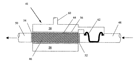
Referring now to Figure 3, a hydrogen production system 41 according to
one embodiment of the invention includes; a reaction chamber 44 having an
inlet 48 and an outlet 50, a gas collection chamber 58 proximate the reaction
chamber 44 and a diaphragm seal 62 that regulates the flow of fuel to the
reaction chamber 56 in response to the pressure in the gas collection chamber
58. As in Figure 2, the inlet 48 and outlet 50 have hydrophilic screens 52 and
54, the reaction chamber 44 incorporates a hydrophobic membrane 56 and a
conduit 60 to direct the hydrogen gas to a fuel cell or device, which utilizes
hydrogen (not shown).
The diaphragm seal 62 is designed with upper and lower regulation
pressures such that when the differential pressure across the diaphragm seal
is
greater than an upper regulation value, the diaphragm 62 extends downward
blocking the inlet 48 and preventing aqueous metal hydride solution from
flowing into the reaction chamber 44. At a pressure less than the upper
regulation value, the memory of the molded diaphragm seal 62 reacts against
the differential pressure and the diaphragm seal 62 partially retracts,
allowing a
limited amount of aqueous metal hydride to flow into the reaction chamber 44.
At a lower regulation value, the diaphragm seal 62 is completely retracted and
the inlet 48 is unobstructed, allowing the maximum amount of aqueous metal
hydride solution to flow into the reaction chamber 44.
Figure 4 depicts a typical response curve for a hydrogen production
system (41, 51, 61, 71, 81, 91, 101 ). For portable fuel cell applications,
the
upper and lower regulation values are typically 5.0 and 1.0 psi. delta
respectively and for large-scale commercial applications, the upper and lower
regulation pressures are in the range of 100 and 20 psi delta respectively. It
should be appreciated that the regulation points and shape of the response
curve can be tailored based on flow requirements of the hydrogen production
system. It should also be appreciated that the regulation pressure can be
sensed at a number of points in the hydrogen production system (41, 51, 61,
71,
CA 02453799 2003-12-19
10019939
81, 91, 101) including the reaction chamber44, reaction chamber inlet 48 and
outlet 50, the gas collection chamber 58 and the conduit 60.
The regulation or upper and lower operating values of the diaphragm seal
62 are defined by the geometry of the seal, the seal material and response
requirements of the system. In addition, the diaphragm seal material is
selected
to withstand the corrosive effects of the aqueous metal hydride solution,
which
for a solution of 10/10/80 (10% sodium borohydride, 10% sodium hydroxide,
80% water) has a ph of approximately 11. For some embodiments, the preferred
diaphragm seal materials include ethylene propylene diene monomer (EPDM)
and silicone rubbers and thermal plastic elastomers (TPE). In an alternate
embodiment, the diaphragm seal 62 is placed in the outlet 50 of the hydrogen
production system (embodiment not shown). In this embodiment, the diaphragm
seal 62 responds to the differential pressure between the outlet 50 and the
gas
collection chamber 58 and regulates the out flow of the aqueous reaction
products from the reaction chamber 44.
Figure 5 depicts a hydrogen production system 51 according to an
alternate embodiment of the present invention. This hydrogen production
system 51 includes a reaction chamber 44 with a porous catalyst 46, a gas
collection chamber 58, an inlet 48 and outlet 50, a conduit 60 and a poppet
valve 64 for regulating the flow of fuel to the hydrogen production system 51.
The poppet valve 64 senses the differential pressure between the inlet 48 and
the gas collection chamber 58. The poppet valve 64 is designed with upper and
lower regulation pressures such that when the differential pressure is greater
than an upper value, the poppet valve 64 fully closes, obstructing the flow of
fuel
to the reaction chamber 44. At a pressure less than the upper regulation
pressure, the poppet valve 64 is partially open allowing a limited amount of
fuel
to flow into the reaction chamber 44. At the lower regulation pressure, the
poppet valve 64 is fuNy open, allowing the maximum amount of fuel to flow into
the reaction chamber 44. Those with ordinary skill in the art will recognize
that
the upper and lower regulation pressures are defined by the geometry of the
poppet valve, the spring constant of the poppet valve, the properties of the
elastomeric seals, and the response requirements of the system.
CA 02453799 2003-12-19
10019939
Figure 6 depicts a hydrogen production system 61 according to an
alternate embodiment of the present invention. This hydrogen production
system 61 includes a reaction chamber 44 with a porous catalyst 46, a gas
collection chamber 58, an inlet 48 and outlet 50, a conduit 60 and a rocker
valve
65 for regulating the flow of fuel to the hydrogen production system 41. A
bladder 66 senses the differential pressure between the inlet 48 and the gas
collection chamber 58 and expands or contracts based on that differential
pressure. The bladder 66 in turn actuates a rocker arm 68, which contacts a
seat 72 and regulates the flow of the fuel to the reaction chamber 44.
The rocker valve 65 is designed with upper and lower regulation
pressures such that when the differential pressure is greater than an upper
value, the bladder 66 fully inflates, extending the rocker arm 68 until it
contacts
the valve seat 72 and obstructing the flow of fuel into the reaction chamber
44.
At a pressure less than the upper regulation value, the rocker arm 68 is
partially
retracted by a spring 70, allowing a limited amount of fuel to flow into the
reaction chamber 44. At the lower regulation value, the bladder 66 is fully
retracted by the spring 70 and the valve seat 72 is completely unobstructed by
the rocker arm 68 allowing the maximum amount of fuel to flow into the
reaction
chamber 44. Those with ordinary skill in the art will recognize that the upper
and
lower regulation values are defined by the geometry of the rocker arm 68, the
constant of the spring 70, the geometry of the bladder 66 and the response
requirements of the system. Again, the selection of materials for the bladder
66
must consider the corrosive effects of the aqueous metal hydride solution and
includes Saranex 11 manufactured by Dow Chemical, polyethylene and liquid
crystal polymer films. In an alternate embodiment, the rocker valve 65 is
placed
in the outlet 50 of the hydrogen production system (embodiment not shown). In
this embodiment, the rocker valve 65 responds to the differential pressure
between the outlet 50 and the gas collection chamber 58 and regulates the out
flow of the aqueous reaction products from the reaction chamber 44.
Referring to now to Figure 7, which depicts a hydrogen production
system 71 according to an alternate embodiment of the present invention. This
hydrogen production system 71 includes a reaction chamber 44 with a porous
CA 02453799 2003-12-19
10019939 9
catalyst 46, a gas collection chamber 58 with inlet 48 and outlet 50, fuel
chamber 85 with an inflatable bag 82 for regulating the flow of fuel into the
reaction chamber 44 and a conduit 60 for conveying the hydrogen gas. The fuel
chamber 85 contains both the fuel, such as NaBH4 and an inflatable bag 82,
which senses the differential pressure between the inlet 48 and the gas
collection chamber 58. The bag 82 is in contact with a spring driven piston 84
and expands or contracts based on this differential pressure.
When the differential pressure between the gas collection chamber 58
and inlet 48 is greater than 5 psi, the bag 82 is fully inflated and prevents
the
spring driven piston 84 from displacing the fuel into the reaction chamber 44.
As
the differential pressure decreases, the bag 82 is partially deflated and
reacts
only a portion of the spring force on the fuel, providing reduced flow to the
reaction chamber 44. When the differential pressure approaches 1 psi, the bag
82 reacts only a small portion of the force exerted on the fuel by the spring
driven piston 84, providing a small reduction in the flow to the reaction
chamber
44. The upper and lower regulation values are determined by the spring
constant of the spring driven piston 84, the geometry of the inflatable bag 82
and the flow requirements of the hydrogen production system 41.
Figure 8 depicts an alternate hydrogen production system 81, in which
the inflatable bag 82 and spring driven piston 84 are replaced with a double
piston 86. The double piston 86 includes a first piston 88, a second piston 90
and an actuation spring 92. The double piston 86 also senses the differential
pressure between the gas collection chamber 58 and inlet 48 and regulates the
inflow of fuel into the reaction chamber 44. When the differential pressure
between the inlet 48 and gas collection chamber 58 is greater than 5 psi, the
hydrogen gas within the collection chamber 58 reacts against the first piston
88,
deflecting the actuation spring 92 and preventing the second piston 90 from
driving the fuel through the conduit 94 into the reaction chamber 44. As the
differential pressure decreases, the hydrogen gas within the collection
chamber
58 reacts with less of the an actuation force in spring 92 and the remaining
force
is reacted by the fuel, providing reduced flow to the reaction chamber 44.
When
the differential pressure approaches 1 psi, a small portion of the actuation
force
CA 02453799 2003-12-19
10019939 10
is reacted by the hydrogen gas and the majority of the actuation force is
reacted
by the fuel, providing the maximum amount of flow to the reaction chamber 44.
Figure 9 depicts a hydrogen production system 91 according to a further
embodiment of the present invention. This hydrogen production system 91
includes a reaction chamber 44 with a porous catalyst 46, a gas collection
chamber 58, an inlet 48 and outlet 50, a conduit 60, a sense line 114, a
piston
pump 112, check valves 116 and 118 and a spring driven piston 84. Initially,
the fuel is driven into the reaction chamber 44 by the spring driven piston
84.
The fuel then reacts with the porous catalyst 46, generating hydrogen gas,
which passes into the gas collection chamber 58, through the conduit 60 and
then to a fuel cell or device, which uses hydrogen. Reaction and waste
products
exit the reaction chamber 44 through a check valve 118 and enter the pump
chamber 110. The piston pump 112, which has different top and bottom surface
areas, moves in response to changes in the differential pressure between the
conduit 114 and pump chamber 110.
At pressures above an upper threshold, the piston in the piston pump
112 moves down, forcing the waste products in the pump chamber 110 to pass
through check valve 116 into the waste collection chamber 55. Simultaneously,
the downward movement of the piston pump 112 causes check valve 118 to
close, preventing the reaction products from back flowing into the reaction
chamber 44 and preventing the flow of fresh fuel into the reaction chamber 44.
This lack of fresh fuel, slows the reaction rates in the reaction chamber 44,
causing the pressure to decrease, which in turn causes the piston in the
piston
pump 112 to move upward. At hydrogen pressures below a lower threshold, the
piston in the piston pump 112 is returned to the extended position. This
allows
more reaction products to enter the pump chamber 110 and fuel to enter the
reaction chamber 44, causing the reaction rate within the reaction chamber 44
to increase and the pressure within the collection chamber 58 and conduit 114
to rise.
Operationally, check valve 118 is designed with a cracking pressure
lower than the pressure generated by the spring drive piston 84 and check
valve
116 is designed with a cracking pressure higher than the pressure generated by
CA 02453799 2003-12-19
10019939 11
the spring driven piston 84, but less than the pressure generated in the pump
chamber 110 by the downward movement of the piston pump 112. Those with
ordinary skill in the art will recognize that the upper and lower regulation
pressures are defined by the geometry of the piston pump 112, the constant of
the piston pump's 112 spring, the cracking pressures of the check valves (116
and 118) and the response requirements of the hydrogen production system 41.
Based on these design parameters, the piston pump 112 is designed with a
lower regulation pressure of 1 psi and an upper regulation pressure of 5 psi.
It should be recognized that there are several variations to the described
piston pump concept including; sequenced valves, staged check valves, flexible
membranes, and other compliant devices. Again, the selection of materials for
the piston pump 112 must consider the corrosive effects of the aqueous metal
hydride solution.
Figure 10 depicts a hydrogen production system 101 according to a
further embodiment of the present invention. This hydrogen production system
101 includes a reaction chamber 44 with a porous catalyst 46, a gas collection
chamber 58, an inlet 48 and outlet 50, a conduit 60 and an electromechanical
valve 102 for regulating the flow of fuel to the reaction chamber 44. In this
embodiment a pressure sensor 104 senses the pressure of the hydrogen gas in
the gas collection chamber 58 and sends a signal to a controller 106. Based on
the signal from the pressure sensor 104 the controller actuates the
electromechanical valve 102 and regulates the flow of the fuel to the reaction
chamber 44.
Depending on the hydrogen production system 101 requirements, the
pressure sensor 104 could be referenced to atmosphere (absolute pressure
sensor), the inlet pressure 48 or the outlet pressure 50. In addition, the
controller 106 could be incorporated in the hydrogen production system 41, an
electrical device powered by the hydrogen production system 41 or a stand-
alone device. The electrical mechanical valve 102 could have a number of
configurations including a ball valve, solenoid valve or rotary activated
valve. In
an alternate embodiment, electrical mechanical valve 102 is placed in the
outlet
CA 02453799 2003-12-19
10019939 12
50 of the hydrogen production system 410 (embodiment not shown) and
regulates the out flow of the reaction products.
Figure 11 is a flow chart, illustrating a method of utilizing the inventive
hydrogen production system (41, 51, 61, 71, 81, 91, 101 ) to power a portable
electrical device 36. The method includes flowing a fuel through a reaction
chamber 120 and reacting the fuel with a catalyst to produce hydrogen gas 122.
The pressure of the hydrogen gas is sensed 124 and based on this sensed
pressure, the flow of fuel is regulated to the reaction chamber 126. The
sensed
pressure could be an absolute pressure or referenced to the reaction chamber
inlet or outlet pressures. The hydrogen that is produced is then reacted in a
fuel
cell to produce electrical energy 128. There are a number of different fuel
cells
that could be used to create react the hydrogen gas including: proton exchange
membrane (PEM) fuel cells, alkaline fuel cells (AFC), phosphoric-acid fuel
cells
(PAFC), solid oxide fuel cells (SOFC) and molten carbonic fuel cells (MCFC).
Lastly, the electrical energy produced is used to power an electrical device
130
which might include: a computer or computational device, cell phone, personal
digital assistant, portable power tool or any other hand held electrical
device.
While the present invention has been shown and described with
reference to the foregoing preferred and alternate embodiments, those skilled
in
the art will understand that many variations may be made therein without
departing from the spirit and scope of the invention as defined in the
following
claims.
This description of the invention should be understood to include all novel
and non-obvious combinations of elements described herein, and claims maybe
presented in this or a later application to any novel and non-obvious
combination of these elements. The foregoing embodiments are illustrative, and
no single feature or element is essential to all possible combinations that
maybe
claimed in this or a later application. Where the claims recite "a" or "a
first"
element of the equivalent thereof, such claims should be understood to include
incorporation of one or more such elements, neither requiring nor excluding
two
or more such elements.