Note: Descriptions are shown in the official language in which they were submitted.
CA 02453865 2004-01-15
WO 03/009001 PCT/US02/22485
APPARATUS AND METHOD FOR
SEISMIC DATA ACQUISITION
BACKGROUND OF THE INVENTION
Field of the Invention
This invention relates generally geologic surveys and more particularly to
an apparatus and method for acquiring and processing seismic data.
Description of the Related Art
Seismic exploration is used to determine the presence of subsurface
structures in earth formations that may contain useful materials such as
hydrocarbons. A conventional system for conducting seismic survey operations
includes acoustic sources, transducers, seismic cables, and a data collection
facility. The acoustic source is used to insonify a subterranean formation.
The
acoustic energy transmitted by the acoustic source radiates generally
downwardly into the earth and is partially reflected back towards the earth's
surface by subsurface acoustic impedance boundaries, called reflectors, which
may exist within the earth. The transducers, which are positioned at or near
the
earth's surface, are used to detect this reflected acoustic energy.
The
transducers generate electrical signals proportional to the magnitude of the
acoustic energy detected. The seismic cables, which are in communication with
the transducers, transmit the electrical signals to the data collection
facility for
processing.
A conventional survey usually requires the deployment of thousands of
transducers and, thus, significant lengths of seismic cables. These seismic
cables are formed of cable segments that are joined by connectors. The
connectors enable the transmission of data between successive cable segments
and, thus, play an integral role in transmitting signals from the transducers
to the
CA 02453865 2009-03-26
data collection facility. The connectors can also be adapted to distribute
power
to the transducers and transmit instructions from the data collection facility
to the
transducers. Moreover, connectors provided with processors can be configured
to convert the analog signals from a transducer into a digital signal.
Exemplary
seismic survey equipment and arrangements are discussed in U.S. Patent No.
5,627,798.
Conventional connectors typically have a housing that includes two
external electrical plugs that couple to seismic cables. The housing can
include
a seal that protects the contents of the housing, such as electrical
circuitry, from
exposure to the environment and means to transfer tension loading from the
cable to the housing without subjecting the electrical connectors to this
tension.
One conventional connector is disclosed in PCT Application No. WO
00/39610, titled "Improved System of Acquiring Geophysical Data" published
June 6, 2000 (hereafter the "'610 PCT App."). The '610 PCT App. describes a
box including two cables each having end pieces, first and second electrical
plugs, first and second platens, and a cover. Each end piece has a flattened
portion. The end pieces are aligned in an opposing fashion such that the
flattened portions present a co-planar surface on which the cover mounts. The
first platen is disposed within the cover and superposed on the flattened
portions. The second platen is fixed on the first platen and supports signal
processing equipment. Electrical communication is established between the
signal processing equipment and first and second cables via first and second
electrical plugs, respectively. Additionally, an 0-ring is provided between
the
cover and connector to seal the box.
It will be appreciated that this conventional connector exemplifies a
number of drawbacks. First, this connector requires two electrical plugs. The
use of two plugs can necessitate additional fabrication time and increases the
number of points of potential failure in the connector. Second, the signal
processing equipment is not provided a sealed environment until the cover is
secured on the cable ends, i.e., the connector is fully assembled. Thus, field
2
CA 02453865 2004-01-15
WO 03/009001 PCT/US02/22485
repair or disassembly/assembly of this conventional connector requires
unsealing the box and leaving the signal processing equipment exposed to the
damaging effects of the elements. Third, the electronics package/processing
circuitry cannot be removed from this conventional connector without
disassembling the cable string. Thus, the task of changing out only the
electronics package inconveniently requires disassembly of the entire box and
disconnecting the seismic cables. Fourth, because the electronics package
cannot be removed, the electronics package cannot be redeployed in a different
location while, for example, the cable is serviced. Thus, this conventional
connector increases the number of electronics packages that must be carried in
inventory to efficiently carry out survey operations.
Still another drawback is that conventional connectors do not permit the
mechanized deployment and retrieval of extended lengths of the cables.
Mechanized deployment and retrieval systems typically have opposing tires that
draw cable from a drum and spool up cable onto a drum or into a storage
container. The opposing tires frictionally engage the cables such that
rotation of
the tires moves the cables in a desired direction.
Unfortunately, some
conventional connectors are not configured to pass through these opposing
tires
because the arrangement of cable and the take-out terminals on conventional
connectors are not compact. Rather, such conventional connectors are bulky
and include protrusions having angles, which may jam into the tires. Moreover,
some conventional connectors have a body length that prevents these
connectors from lying flat on the arcuate surface of a drum.
The present invention addresses these and other limitations of
conventional connectors.
SUMMARY OF THE INVENTION
The present invention relates to a seismic data acquisition system that
minimizes deployment costs and provides enhanced protection electrical
components. The system includes a data acquisition unit utilized in a seismic
array made up of seismic data carriers (e.g., cables) and transducers. The
3
CA 02453865 2004-01-15
WO 03/009001 PCT/US02/22485
system can utilize analog signals, digital signals or a combination of both.
For
example, the transducers may transmit analog signals that are converted to
digital signals at one or more of the data acquisition units. Alternatively, a
processor positioned proximate to the transducer can perform the conversion
and transmit a digital signal to the data acquisition unit.
The data acquisition unit includes a connector housing and a mating
electrical circuitry module. The electrical circuitry module houses electrical
circuitry whereas the connector housing consolidates at a single location the
seismic data carrier to be in communication with the electrical circuitry. A
single
interface or connector couples the cable to the electrical circuitry.
Preferably, the
connector housing and electrical circuitry module are provided with
independent
seals such that a contaminant-proof barrier is maintained in the connector
housing and electrical circuitry module whether or not these two parts are
mated.
Further, the connector housing incorporates an anchor for the wiring
associated
with the cables such that tension in the cable is transferred into the
connector
housing without loading the single connector.
An alternate data acquisition unit also includes a connector housing and a
mating electrical circuitry module. The alternate connector housing has two
plug
casings, each of which is provided with a plug. The alternate unit includes
two
receptacles complementary to the plugs and an interior space adapted to hold
the electrical circuitry. Preferably, the electrical circuitry module is
provided with
seals such that a contaminant-proof barrier is maintained in the electrical
circuitry
module whether or not the connector housing is mated to the electrical
circuitry
module. The plug casings are secured to the electrical circuitry module with
fasteners. Alternatively, a locking pin disposed within the plug casing can be
used to selectively engage the electrical circuitry module. Rotation of the
locking
pin brings a finger formed on the locking pin to move in and out of locking
engagement with a surface on the electrical circuitry module.
As can be seen, the data acquisition unit is simple, rugged, and
compatible with mechanized cable deployment and retrieval systems:
4
CA 02453865 2004-01-15
WO 03/009001 PCT/US02/22485
The present invention also provides methods that establish electrical
communication between electrical circuitry and the cables and transducers
making up a seismic array. A method includes providing a single electrical
interface through which a cable communicates with the electrical circuitry.
This
method can also include preventing contaminants from contacting the electrical
circuitry.
Thus, the present invention comprises a combination of features and
advantages that enable it to overcome the deficiencies of prior systems and
methods. The various characteristics described above, as well as other
features,
will be readily apparent to those skilled in the art upon reading the
following
detailed description of the embodiments of the invention, and by referring to
the
accompanying drawings.
It should be understood that examples of the more important features of
the invention have been summarized rather broadly in order that detailed
description thereof that follows may be better understood, and in order that
the
contributions to the art may be appreciated. There are, of course, additional
features of the invention that will be described hereinafter and which will
form the
subject of the claims appended hereto.
DESCRIPTION OF THE FIGURES
For a detailed description of an embodiment of the invention, reference
will now be made to the accompanying drawings wherein:
Figure 1 schematically illustrates an embodiment of a seismic survey
array made in accordance with the present invention;
Figure 2A schematically illustrates a portion of the Figure 1 seismic
survey array that incorporates an embodiment of a seismic data acquisition
system made in accordance with the present invention wherein a seismic data
acquisition unit made in accordance with the present invention performs analog
to digital processing;
Figure 2B schematically illustrates a seismic survey array made in
accordance with the present invention wherein a digitizer positioned proximate
to
5
CA 02453865 2004-01-15
WO 03/009001 PCT/US02/22485
a transducer transmits digital signals to an embodiment of a seismic data
acquisition unit made in accordance with the present invention;
Figure 3A illustrates an isometric exploded view of an embodiment of a
seismic data acquisition unit made in accordance with the present invention;
Figure 3B illustrates a cross-sectional side view of the Figure 3A
embodiment of the present invention in an assembled state;
Figure 4A illustrates a cross-sectional side view of an enclosure shown in
the Figure 3A embodiment of the present invention;
Figure 4B illustrates a cross-sectional side view of an enclosure utilizing
an exemplary support made in accordance with the present invention;
Figure 5A illustrates a cross-sectional side view of an alternate take-out
arrangement wherein the take-out includes a banana-type plug;
Figure 5B illustrates a cross-sectional side view of another alternate take-
out arrangement wherein the take-out includes an overmolded pig-tail;
Figure 5C illustrates an isometric view of still another alternate take-out
arrangement wherein the take-out is substantially integrally molded onto the
enclosure;
Figure 6 illustrates an isometric exploded view of an alternate
embodiment of a seismic data acquisition unit made in accordance with the
present invention;
Figure 7 illustrates a cross-sectional side view of a lock made in
accordance with the present invention;
Figure 8A schematically illustrates an exemplary arrangement for
deploying an seismic data acquisition unit made in accordance with the present
invention;
Figure 8B schematically illustrates an alternate arrangement for
deploying a seismic data acquisition unit made in accordance with the present
invention onto a continuous portion of a seismic cable; and
Figure 8C schematically illustrates another alternate arrangement for
deploying a seismic data acquisition unit made in accordance with the present
6
CA 02453865 2004-01-15
WO 03/009001 PCT/US02/22485
invention onto a continuous portion of a seismic cable wherein the cable to
the
one or more transducers runs external to the seismic cable.
DETAILED DESCRIPTION OF THE INVENTION
The present invention relates to devices and methods providing rugged
and cost-effective interface for seismic signal data carriers. The present
invention is susceptible to embodiments of different forms. There are shown in
the drawings, and herein will be described in detail, specific embodiments of
the
present invention with the understanding that the present disclosure is to be
considered an exemplification of the principles of the invention, and is not
intended to limit the invention to that illustrated and described herein.
The teachings of the present invention can be advantageously applied to
nearly any situation that requires the transmission of analog and/or digital
signals
through reliable and robust interfaces. For simplicity, the embodiments of the
present invention will be described in the context of systems and equipment
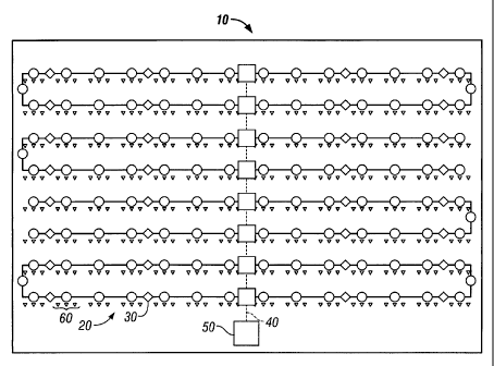
suited for performing seismic surveys. Referring initially to Figure 1, there
is
diagrammatically shown a seismic survey system 10 made in accordance with
the present invention. The seismic survey system 10 includes physical data
carriers such as seismic cables generally referred to with numeral 20, battery
booster units 30, cross-line units 40, and a data collection facility 50. In
other
embodiments, the data carrier can utilize wave transmissions.
These
components and equipment are known in the art and will not be discussed in
detail. Referring now to Figure 2A, the seismic survey system 10 also includes
a seismic data acquisition system 60 that is provided with one or more
transducers 40, data carriers such as cross-line cables 42, and a data
acquisition
unit 100. The transducer 40 can be any device that converts acoustic energy
into signals representative of the detected energy. Exemplary transducers 40
include, but are not limited to, geophones, hydrophones, one-axis
accelerometers, and multi-axis accelerometers. The seismic data acquisition
7
CA 02453865 2004-01-15
WO 03/009001 PCT/US02/22485
unit 100 facilitates the transmission of data and/or power between the
transducers 40 and other system 10 components. The signal transmission
media for data and/or power exchange is preferably one or more seismic signal
data carriers. As noted above, other transmission media, such as RF
transmitters, may be used in certain applications.
The data acquisition system 60 may be configured to collect and process
data of various parameters of interest and transmit this data with analog
signals,
digital signals, or a combination of these signals. For example, referring
still to
Figure 2A, the data acquisition system 60 may be configured such that the
transducers 40 transmit an analog signal via the cross-line cables 42 or take
out
cable 44 to the data acquisition unit 100. The unit 100 can include a
processor
that converts the analog signal transmitted by the transducers 40 into digital
signals for processing and re-transmission.
Referring now to Figure 2B, there is shown an alternate system 70
wherein an analog-to-digital converter 72 is positioned proximate to the =
transducer 40. For example, the converter 72 may be integrated into the
transducer 40 or be a stand-alone unit interposed between the transducer 40
and the data acquisition unit 100. By digitizing the seismic data early in the
transmission, the system 70, including the data acquisition unit 100, can be
configured to process and transmit data in primarily a digital format.
Referring now to Figure 3A, the seismic data acquisition unit 100, an
embodiment of which is described below, cooperates with the seismic data
acquisition system, the exemplary embodiments of which have been discussed
above, to collect, process and transmit seismic data and power. An exemplary
unit 100 includes electric circuitry 140, an electric circuitry module 200,
and a
connector housing 300.
The electric circuitry 140 includes processing software and hardware that
can receive, process, transmit seismic data and can communicate with other
externally coupled devices. By "coupled," it is meant that an exchange or
transfer of data/power is enabled by a physical connection (electrical or
optical
8
CA 02453865 2004-01-15
WO 03/009001 PCT/US02/22485
wires and connectors) or non-physical connection (e.g., inductive, RF,
acoustic).
The electric circuitry 140 can include analog-to-digital converters coupled to
input
from each transducer 40 associated with the seismic data acquisition system
100. The circuitry 100 further includes one or more buffers or memory for
storing
digitized signals transmitted from other devices such as seismic data
acquisition
units and signals from the analog-to digital circuit. The circuitry 140
further
includes one or more transceivers that transmit at a predetermined data rate
digital signals from the buffers and the analog-to-digital converters to other
devices such as seismic data acquisitions or a control unit connected to the
seismic data unit 100. A transceiver in the seismic acquisition unit 100
receives
control or command signals from a control unit and retransmits such control
signals to other devices such as seismic data acquisition units coupled to the
unit
100. The transceiver may comprise optical telemetry transceivers. One or more
central processing units performs data manipulation operations on seismic data
from detectors and controls the operations of other components in the
circuitry
140 according to programmed instructions on models stored in the circuitry 140
and/or at a remote location. As explained above, the circuitry 140 may also be
adapted to operate in a fully digital environment wherein the circuitry 140
receives digital signal input from one or more transducer lines. Further, the
circuitry 140 may be adapted to distinguish between different data types and
selectively receive and process such data.
Referring still to Figure 3A, a preferred electric circuitry module 200
provides the electric circuitry 140 with a sealed environment that is kept
substantially free of contaminants such as dirt or moisture. This sealed
environment exists whether or not the electric circuitry module 200 is secured
to
the connector housing 300. When the connector housing 300 is mated with the
electric circuitry module 200, a single interface for communication is
established
between circuitry 140 and the signal data carriers at the connector housing
300.
In a preferred embodiment the interface is formed of electrical components.
The
preferred electric circuitry module 200 includes a casing 210, a receptacle
230, a
9
CA 02453865 2004-01-15
WO 03/009001 PCT/US02/22485
receptacle seal 240, a support board 250, a lid 260, a lid seal 280, and
fasteners
290.
The casing 210 includes a shell 212, a flange 214, and a groove 216.
The shell 212 is a generally oblong structure having a rim 218 and an interior
space 220 configured to accept the electric circuitry 140. In order to
maintain a
generally compact configuration for the unit 100, the shell 212 is no larger
than
that required to accommodate electric circuit 140 in the interior space 220.
The
flange 214 is formed along the shell rim 218 and acts as a seating surface for
the
lid 260. The flange 214 includes holes 222 that are disposed on the outer
corners of the casing 210. The holes 222 are adapted to receive fasteners 290
that secure the lid 260 against the flange 212 and the casing 210. The groove
216 is formed generally contiguously along the shell rim 218 and is adapted to
receive the lid seal 280. The lid seal 280, when compressed between the flange
214 and the lid 260, provides a barrier against the intrusion of contaminants
such
as moisture and dirt into the interior space 220. The interior space 220 is
preferably filled with a foam-like material (not shown) in which the electric
circuitry 140 is suspended and protected from shock and vibrations.
Referring now to Figures 3A and 3B, the lid 260 operates as a removable
closure for the casing 210. The lid 260 is a generally planar member having an
opening 262, a lip 264, a first set of holes 266, a second set of holes 267, a
first
set of posts 268, an upper surface 270 and a lower surface 272. The opening
262 provides access to the interior space 220 and is formed complementary to
the receptacle 230. The seal 240, such as a radial o-ring, is radially
disposed
about the receptacle 230 and thereby provides a barrier against the intrusion
of
contaminants such as moisture and dirt into the housing interior space 220.
The lip 264 distributes the clamping force of the fasteners 290 generally
evenly along the lid seal 280. The lip 264 is formed as a raised shoulder
formed
along the perimeter of the lid 260. Further, the lip 264 may be configured to
provide an abutting surface 265 within which the connector housing 300 seats.
The abutting surface 265 prevents the connector housing 300 from sliding
CA 02453865 2004-01-15
WO 03/009001 PCT/US02/22485
relative to the lid upper surface 270 during assembly of seismic data
acquisition
unit 100.
Referring now to Figure 3A, the fasteners 290 secure the lid 260 onto the
casing 210. The fasteners 290 extend through the holes 222 of the flange 214
and the first set of internally threaded holes 266. Alternatively, the first
set of
holes 266 may be provided with internal threads that are complementary to the
fasteners 290. Preferably, the holes 222 and 266 should be arrayed so as to
promote a distributed clamping force on the lid seal 280 when the fasteners
290
are tightened. The holes 267 are blind internally threaded holes adapted to
engage the fasteners 290 that secure the connector housing 300 to the lid 260.
It should be understood that the fasteners 290 and associated holes 222 and
266 are merely one of several arrangements that may be used to secure the lid
260 against the casing 210. Such variations will be apparent to one of
ordinary
skill in the art.
The receptacle 230 presents the single communication interface between
the electric circuitry 140 and the connector housing 300. The receptacle 230
may be a conventional electrical connector having a male, female or any other
interface that is suited to enable data exchange and/or power transmission.
For
example, the interface can be adapted to use known transmission media such as
RF, optical, acoustic, electromagnetic, and induction. Thus, the receptacle
230
can use either a physical signal transmission medium (e.g., copper wire or
fiber
optical wire) or energy waves. The receptacle 230 includes a reduced diameter
connection end 232 that protrudes through the lid opening 262 and a base 234
that is configured to electrically couple with the support board 250. The
receptacle seal 240 is radially disposed about the base 234 and thereby
prevents contaminants from entering the housing interior space 220 through the
opening 262. When the connector housing 300 is removed from the casing 210,
a plastic cap or other sealing member (not shown) may be fitted onto
connection
end 232 to protect the receptacle 230. In other embodiments, the receptacle
11
CA 02453865 2004-01-15
WO 03/009001 PCT/US02/22485
230 is not fixed onto the circuitry module 200 but either "floats" in a foam
or is
fixed to the electric circuitry 140. In such embodiments, the lid can be
omitted.
The support board 250 provides a mounting platform for the receptacle
230. The support board 250 may be a known printed circuit board or similar
structure. The support board 250 includes thru-holes 252 and a wiring
interface
configured to mate with the receptacle 230. Preferably, the support board 250
is
fixed to the lower surface 272 of the lid 260. For example, fasteners (not
shown)
fitted through the holes 252 can mate with internally threaded holes (not
shown)
formed into the first set of posts 268 of the lid 260. The electric circuitry
140 is
connected to the support board 250 by known electrical wiring such as ribbon
wires.
From the above, it can be seen that the electric circuitry module 200 is a
portable, reliable and rugged casing for transporting and housing the electric
circuitry 140. For example, the electric circuitry module 200 may be detached
from the connector housing 300 and carried to a service facility for repair
without
exposing the electric circuitry 140 to contaminants. Moreover, the use of a
single
receptacle simplifies initial assembly and facilitates trouble-shooting for
defective
parts. Furthermore, the electric circuitry module 200 minimizes the need for
multiple and expensive electrical connectors by consolidating electrical
wiring at
a single receptacle.
Referring now to Figure 4A, the connector housing 300 collects the
various communication and/or power carriers or lines from transducers,
neighboring seismic data acquisition units, and other equipment and
consolidates the carriers at a single interface. Where an electrical interface
is
used, a preferred connector housing 300 is a structure that includes a body
302,
a take-out 304 and a plug 306. For example, the connector housing 300 is
generally unitary and may be fabricated through known processes such as
molding, stereolithography, welding, or machining.
The body 302 includes barrels 308, a clamp 310, an anchor 311, a
conduit 312, a first cavity 314, and a second cavity 316. The barrels 308 are
12
CA 02453865 2004-01-15
WO 03/009001 PCT/US02/22485
cylindrical protuberances extending from the body 302. The barrels 308 are
preferably arranged in an opposing fashion on the body 302 such that the
cables
and data carriers 42 are axially aligned. Other alignments, however, may be
suitable. It can be seen that such an arrangement will facilitate the laying
or
retrieval of an extended lengths of the cables 42 that incorporate the unit
100.
The barrels 308 have inlets 318 adapted to receive cable ends 43. A portion of
the inlets 318 includes internal threads 319. The clamp 310 captures the cable
ends 43 within the barrel 308. The clamp 310 uses a gland seal-type
arrangement that includes a compression nut 320, a washer 322, a collet 324,
and a spacer 326. The external threads of the clamp 310 engage the internal
threads 319 formed within the inlet 318. When threaded into inlet 318, the
clamp
310 urges the washer 322 into abutting engagement with an annular step 128 of
a cable handle 127. The relatively soft cable handle 127 deforms under
compression and seals inlet 318. At the same time, the cable handle 127 drives
the collet 324 into the spacer 326. The collet 324 applies a clamping force on
cable end 43 when so driven. Thus, it should be appreciated that the clamp 310
provides a sealed termination between the body 302 and cable 42 at the barrel
308. It should also be appreciated that cable end 43 may be disconnected from
the body 302 by simply removing the compression nut 320. Thus, the clamp 310
provides a reusable securing mechanism. Alternatively, cable ends 43 may be
secured within the barrels 308 with an over mold or overmolding (not shown)
formed at least partially of a plastic such as polyurethane. This overmolding
encapsulates the barrel 308 and a portion of the cable 42 extending out of the
inlet 318.
The first cavity 314 and the second cavity 316 secure the take-out 304
and the plug 306, respectively, within the body 302. The take-out 304 and the
plug 306 may be fixed within their respective cavities 314, 316 by means of
fasteners (not shown) that extend through holes in flanges (not shown)
provided
on the take-out 304 and the plug 306. Seals 328 and 330 are fitted onto the
take-out 304 and the plug 306, respectively. Tightening of the fasteners (not
13
CA 02453865 2004-01-15
WO 03/009001 PCT/US02/22485
shown) causes seals 328 and 330 to be compressed between the body 302 and
the take-out 304 and the plug 306, respectively. Thus, first and second
cavities
314 and 316 are sealed so that contaminants cannot enter the interior of the
body 302.
The first cavity 314 includes a wire well 332 that is a relatively smaller
cavity adapted to store a portion of the wiring extending from the take-out
304.
The second cavity 316 provides a collection point for the various wires
entering
the body 302 and is defined by an inner wall 317. The conduit 312 provides
communication between the first cavity 314, the second cavity 316 and the
inlets
318. The conduit 312 is composed of one or more channels formed within the
body 302. Thus, the wires of the cables 42 travel from the inlets 318 through
the
conduit 312 to the second cavity 316. Similarly, the wires connected to the
take-
out 304 extend from the first cavity 314 through the conduit 312 to the second
cavity 316.
Referring now to Figures 4A and B, the anchors 311 transfer tension or
tractive force from the cables 42 to inner wall 317, and ultimately to the
body
302, without loading the connection between the wiring 336 and the plug 306.
The anchor 311 is substantially rigid body that engages the body 302 and
provides an attachment surface for a tension member 124. In one embodiment,
an 0-shaped member, such as a washer, has a center bar 334. The wiring 336
extending out of the cable end 43 terminates at the plug 306. A tension member
(e.g., KEVLAR core or similar material) 124 of the cable 42 wraps around the
center bar 334 but does not connect to the plug 306. Glue, such as an epoxy
resin, is applied to the wrappings of the tension member 124, thereby securing
the wrappings to the center bar 334 of the anchor 311. The anchors 311 are
positioned adjacent the inner wall 317. Thus, a tension loading applied to
cable
42 will be transferred to the body 302 via the tension member 124 wrapped
around the center bar 334 of the anchor 311. In another embodiment, the
anchor 311 may be a potted cup, disk or cylindrical member that is disposed
within conduit 312 adjacent to inner wall 317. The potted cup includes a wire
14
CA 02453865 2004-01-15
WO 03/009001 PCT/US02/22485
channel and a tapered tension member channel. The wiring 336 passes through
the wire channel and connects with the plug 306 (Figure 4A). The tension
member 124 passes through the tension member channel and attached to the
potted cup, the inner wall 317, or other convenient structure. The attachment
may be accomplished by known mechanical devices or a chemical adhesive
such as a cyanoacrylate compound. In either case, because of the anchoring
effect of the anchor 311 against inner wall 317, the span of the wiring
between
the anchor 311 and the plug 306 remains generally slack. Thus, only minimal,
if
any, loading is imposed on the plug 306. Under normal conditions, the anchor
311 is held against the inner wall 317 by the pre-tension in the tension
member
124.
The plug 306 presents a single interface for the one or more cables and/or
take-out consolidated at connector housing 300. The plug 306 may be a
conventional electrical connector that has a male, female or any other
interface
that is suited to enable data exchange and/or power transmission. The plug 306
is a known electrical connector that is complementary to receptacle 230. It
should be appreciated that plug 306 and receptacle 230 are only one of many
types of electrical connections that are available to establish communication
between electrical circuitry 140 and the other equipment and cables used to
perform the seismic activity. Accordingly, other non-electrical interfaces
(e.g.,
electromagnetic, induction, RF, optical, acoustic) may be used with equal
effectiveness depending on the particular type of telemetry system used. In
certain embodiments, the plug 306 is loosely disposed rather than fixed in the
connector housing 300.
Referring now to Figure 3A, the take-out 304 is an connection point that
enables communication with an externally connected device such as the
transducer 40. The take-out 304 is adapted to exchange data and/or transmit
electrical power and is available from known manufacturers in any number of
configurations. As discussed above, other interfaces suited to enable data
exchange and/or power transmission can also be used. Generally speaking, the
CA 02453865 2004-01-15
WO 03/009001 PCT/US02/22485
take-out 304 may be considered as having a face 305. The face 305 represents
the physical orientation of the take-out 304 with respect to the connector
housing
300. The take-out face 305 may be positioned at any angle a from the axis A of
the cable 42. Furthermore, the take-out face 305 may be rotated any angle p
about axis A. It is preferred, however, that the take-out 304 remain generally
grouped with the terminations for the cables 42 so as to maintain a compact
profile for the seismic data acquisition unit 100.
Referring now to Figure 5A, there is shown another take-out terminal
arrangement 400. The take-out terminal arrangement 400 includes a terminal
402, wiring 404, overmolding 406 and an optional cap 408. The terminal 402 is
a banana plug-type interface that accepts a complementary connection from the
wiring associated with a transducer (not shown). The wiring 404 has a first
end
410 connected to the terminal 402 and a second end 412 that connects with the
plug 304. The overmolding 406 encases portions of the terminal 402 and the
wiring 404 in a molded block that is shaped complementary the first cavity
314.
0-rings and other sealing members may be used as needed to provide a sealed
termination at the first cavity.
Referring now to Figure 5B, there is diagrammatically shown another
take-out terminal arrangement 420. The take-out terminal arrangement 420
includes a pig-tail 422, overmolding 424 and wiring 426. The wiring 426 at one
end connects, either directly or indirectly, to a transducer 40 (Figure 2) and
at the
other end 428 connects with the plug 304. The overmolding 424 encases at
least a portion of the pig-tail 422 in a molded block that is shaped
complementary the first cavity 314. The take-out terminal arrangement 420 may
use fasteners or other devices (e.g., clips) or a quick disconnect mechanism
(not
shown) to secure the pig-tail 422 within the first cavity 314. 0-rings and
other
sealing members (not shown) may be used as needed to provide a sealed
termination at the first cavity 314.
Referring now to Figure 5C, there is diagrammatically shown another
take-out terminal arrangement 440. The take-out terminal arrangement 440
16
CA 02453865 2004-01-15
WO 03/009001 PCT/US02/22485
includes overmolding 442 that encapsulates a take-out 444. The take-out 444
connects to a transducer 40 (Figure 2) at one end and connects with the plug
304 (Figure 3) at the other end. The overmolding 442 encases the wiring
associated with the take-out in a molded block that effectively renders the
wiring
an integral component of the housing connector 300 (Figure 3). Alternatively,
a
commercially available take-out connector (not shown) may be mated with
connector housing 300 and an overmolding formed thereon.
From the above, it can be seen that data acquisition unit 100 provides a
compact design having independently sealed components. For example, it will
be appreciated that the use of a single connector interface provides a compact
design and facilitates the mechanized deployment and retrieval of the cables
utilizing the unit 100. For example, the relatively short length of the unit
100
enables the unit 100 to lay flat on the arcuate surface of a drum. Moreover,
the
width and thickness of the unit 100 can be generally accommodated within the
rotating tires or wheels of mechanized deployment and retrieval systems, such
as a squirter.
It should be understood that the above-described features of seismic data
acquisition unit 100 are subject to numerous adaptations and variations. For
example, certain elements are described as having separate parts but such
elements may be formed as one integral element. Other elements may have
interchangeable substitutes. For example, lock rings, glue, and clamping
mechanisms may be used instead of threaded fasteners. Further, one or more
of the fasteners described may be replaced with a quick-disconnect mechanism
as discussed below or other similar arrangements.
Referring now to Figure 6, there is shown an alternate embodiment of a
seismic data acquisition system. Alternate seismic data acquisition unit 500
includes an enclosure 600 and an electrical circuitry module 700 and is also
used in conjunction with the cables 44 and the electric circuitry 140. As will
be
seen, the alternate unit 500 provides selective connecting/disconnecting for
the
17
CA 02453865 2004-01-15
WO 03/009001 PCT/US02/22485
cables 42 and also seals the electric circuitry 140 in a self-contained and
detachable compartment.
The enclosure 600 provides separate termination points for the various
seismic data carriers that are intended to be in communication with the
electric
circuitry 140. The enclosure 600 has first and second plug casings 602,604 and
a take-out casing 606.
The plug casings 602,604 each include a plug 608, wiring (not shown),
and an overmolding 610. Because the plug casings 602 and 604 are
substantially identical, the following description will only make reference to
the
plug casing 602 with the understanding that the description equally applies to
the
casing 604. The wiring (not shown) associated with the plug casing 602 extends
from the cables 42 and terminates at the plug 608. The overmolding 610
provides a sealed and resilient covering for the plug casing 602 by
encapsulating
portions of the plug 608, the wiring (not shown) and cable 42 in a block of
polymer such as polyurethane. The overmolding 610 includes a cavity (not
shown), a bottom face 612, an inner face 614 and holes 616. The plug 608 is
disposed within the cavity and includes a hub 618, an electrical connector
620,
and a plurality of ears 622. The hub 618 has a central passage 624 in which
the
electrical connector 620 is fixed. The portion of electrical connector 620
adapted
to mate with electrical circuitry module 700 protrudes from the bottom face
612.
The remainder of electrical connector 620, however, is sealed within the
overmolding 610. The hub ears 622 are semi-cylindrical supports that radiate
outwardly from the hub 618. One ear 622 is oriented such that a tongue 626 is
formed along the inner face 614. Each ear 622 is provided with a passage 628
in axial alignment with an overmolding hole 616. The plug casing 602 is
secured
to electrical circuitry module 700 by fasteners (not shown) that extend
through
each hole 616 and associated passage 628 and engage electrical circuitry
module 700.
The take-out casing 606 is centrally positioned on electrical circuitry
module 700 and provides a connection point between a transducer (not shown)
18
CA 02453865 2004-01-15
WO 03/009001 PCT/US02/22485
and the electric circuitry 140. The take-out casing 606 includes a housing
630, a
column 632, a seal 634, and a snap-ring 636. The housing 630 is adapted to
receive the cables and wiring from the transducer. The housing 630 includes
opposing outer walls 638 that abut the inner faces 614 of the plug casing
overmolding 610 and also includes a passage (not shown) adapted to receive
the wiring. Each outer wall 638 has a groove 640 that is complementary to the
tongue 626. The tongue 626 and groove 640 cooperate to properly align the plug
casings 602, 604 and take out casing 606. The column 632 is a cylindrical
member formed on the housing 630 that fixes the take-out casing 606 to
electrical circuitry module 700. The column 632 includes a bore (not shown)
and
grooves (not shown) associated with seal 634 and the snap-ring 636. The bore
communicates with the housing passage and acts as a conduit through which
the wiring passes before entering electrical circuitry module 700.
As generally noted earlier, the take-out plug 606 may be positioned at any
angle a from the axis A of cable 42. Furthermore, the take-out plug 606 may be
rotated any angle f3 about axis A. It is preferred, however, that the take-out
plug
606 remain generally grouped with the terminations for the cables 42 so as to
maintain a compact profile for alternate seismic data acquisition unit 600.
Furthermore, the plug casing inner face 614 and outer walls 638 may be
arranged to optimize the structural integrity and load bearing characteristics
of
the plug casing 602,604 and take out casing 606. For example, the inner face
614 can incorporate a negatively sloped surface that induces a clamping force
against a positively sloped surface on outer walls 638. For example, outer
walls
638 of the take-out casing 606 may be inwardly inclined at an angle of three
to
five degrees to receive the inner faces 614 having a complementary negative
slope, or undercut. In such an arrangement, the take-out casing 606 is
captured
between the plug casings 602 and 604. The plug casings inner faces 614 and
the take-out casing outer walls 638 may also be arranged to incorporate
interlocking fingers (not shown) that can transmit a tension from cable 42
through
the plug casing 602,604 to the take-out casing 606.
19
CA 02453865 2004-01-15
WO 03/009001 PCT/US02/22485
The alternate electrical circuitry module 700 mates with the enclosure 600
and provides the electric circuitry 140 with a sealed environment that is
substantially free of contaminants such as dirt or moisture. This sealed
environment exists whether or not the plug casings 602,604 are secured to the
enclosure 600. The alternate electrical circuitry module 700 includes a
housing
702, receptacles 704, receptacle seals 706, a support board 708, a lid 710, a
lid
seal 712 and fasteners 714. The housing 702, the receptacle seals 706, the lid
seal 712 and the fasteners 714 are substantially similar to corresponding
elements described with respect to the unit 100. Accordingly, descriptions for
these and related elements will not be repeated.
The lid 710 operates as a removable closure for the housing 702. The lid
710 is a generally planar member having openings 716, an orifice 718, a
plurality
of holes 722, posts 724, an upper surface 726, and a lower surface 728. The
openings 716 are each configured to receive the receptacle 704. The seal 706,
such as a radial 0-ring, seals the joint between the opening 716 and the
receptacle 704. The holes 722 are arrayed around the openings 716 in a pattern
complementary to ear passages 628. Preferably, the holes 722 are blind, i.e.,
they do not penetrate through the lid 710 in a manner that compromises the
sealed nature of electrical circuitry module 700. Internally formed threads
(not
shown) provided in the holes 722 mate with fasteners (not shown). The orifice
718 provides an access through the lid 710 for the take-out casing 606 and is
adapted to closely receive column 632 of the take-out casing 606. Snap ring
636, when installed into a groove (not shown) in column 632, fixes the take-
out
casing 606 such that the take-out casing housing 630 seats on the lid upper
surface 726 and snap ring 636 seats against the lid lower surface 728. Seal
634, when installed into a groove (not shown) in column 632, provides a
barrier
between column 632 and the lid 710. Thus, it can be seen that the openings 716
and orifice 718 are all provided with seals that provide a barrier against
intrusion
of contaminants into the housing 702.
CA 02453865 2004-01-15
WO 03/009001 PCT/US02/22485
The plug casings 602,604 of the enclosure 600 are fastened to electrical
circuitry module 700 by the fasteners (not shown). As noted earlier, the
fasteners extend through the passages 628 and the holes 616 and engage the
holes 722 in the lid 710. Referring now to Figure 7, an alternate locking
arrangement includes a locking pin 800, alternate plug 802, and an associated
receptacle 804. The locking pin 800 includes a head 806, an elongated shank
808, and a finger 810. The finger 810 is a flattened member that protrudes
generally perpendicularly from one end of the shank 808. The head 806 is
formed on the other end of the shank 808 and has means, such as a bale, that
facilitates rotation. Alternate plug 802 includes a top face 812 on which the
locking pin head 806 seats and a central passage 814 adapted to receive the
shank 808. The finger 810 and a portion of the shank 808 protrude out of the
bottom face 813 of the alternate plug 802. The receptacle 804 is provided with
a
bore 816 and a seat 818. The bore 816 is a generally slotted passage
configured to allow insertion and removal of the shank 808 and the finger 810.
The seat 818 is a surface formed on the receptacle 804 that receives the
finger
810. Thus, under this alternate locking arrangement, the plug casing 602 (or
604) is positioned on the lid 710 such that the plug 802 and the receptacle
804
are generally aligned. Thereafter, the exposed shank 808 and the finger 810
are
inserted into the receptacle bore 818 until the finger 810 is generally
positioned
adjacent to the seat 818. Rotation of the shank 808 brings the finger 810 into
engagement with the seat 818. Because the engagement between the finger
810 and the seat 818 prevents axial movement of the shank 808, the locking pin
800 clamps the plug casing 602 against electrical circuitry module 700. It
should
be appreciated that this alternate locking arrangement facilitates assembly
and
disassembly. It should also be appreciated that the described alternate
locking
arrangement may be also adapted to replace one or more of the fasteners
described in relation to the above-described embodiments.
Further, one or more housing components may be include a material that
exhibits static electricity discharge properties. For example, a conductive
21
CA 02453865 2004-01-15
WO 03/009001 PCT/US02/22485
material such as aluminum may be used to allow any accumulated static
electricity to be discharged into the environment. Also, as an alternative or
in
combination, a conductive surface treatment may be applied to obtain the
desired static electricity dissipation properties for the seismic data
acquisition
unit.
It will be appreciated that alternate seismic data acquisition unit 600 is
compact and amenable to mechanized deployment and retrieval. Further, it can
be seen that the casings 602,604,606 each provided with individual connections
to electrical circuitry module 700. Thus, for example, field repair or testing
may
be done on the plug casing 602 without disturbing the connections associated
with the plug casing 604 or the take-out casing 606. Furthermore, such work
may be accomplished without exposing the electric circuitry 140 to the field
environment and its inherent contaminants.
The deployment of an exemplary data acquisition unit 100 with now be
discussed with reference to Figures 8A-C. Referring first to Figure 8A, there
is
diagrammatically shown a data acquisition unit 100A operatively connected to a
signal/power transmission media 42 (shown in broken lines). The signal/power
transmission media 42 can include one or more tension members 812 (assuming
a physical media such as wiring is used), one or more seismic signal data
transmission (telemetry) lines 814, one or more power transmission lines 816,
and one or more transducer lines 818. It should be understood that the term
"lines" is used to denote a path for "hard wire" communications and well as
transceiver devices for wave transmissions. The lines are shown as separate
components merely for convenience. A single line may function, for example, as
both the telemetry line and the power line. Such an arrangement is, therefore,
within the scope of the present invention. The tension member 812 is typically
a
KEVLAR core, or similar material, that is disposed longitudinally along the
cables 22. In this embodiment, the connector housing 802 of the unit 100A
provides a mechanical and electrical connection between adjacent cables 22. A
single interface/connector assembly 806 for establishes power and data
transfer .
22
CA 02453865 2004-01-15
WO 03/009001 PCT/US02/22485
between the connector housing 802 and the electric circuitry module 804. The
electric circuitry module 804 of the unit 100A can include circuitry that
processes
the signals received from one or more transducers via wires 818 and transmits
such processed signals to other seismic data acquisition units or a control
unit
connected thereto. The circuitry also receives and retransmits control or
command signals sent by a control or a central unit to other seismic data
acquisition units via the data transmission lines 814. In this manner the
circuitry
in each seismic data acquisition unit 100A can process seismic sensor data
received from detectors and provide two-way data and signal communication
with other serially connected seismic data acquisitions and/or control units.
Referring now to Figure 8B, there is diagrammatically shown an alternate
embodiment of the present invention wherein a seismic data acquisition unit
1006 is mounted on a substantially continuous length of a seismic cable 42
(shown in broken lines). The cable 42 can include one or more tension members
812, one or more signal data transmission carriers or lines 814, one or more
power transmission lines 816, and one or more transducer lines 818. The
tension member 812 remains continuous within the cable 42. In this
embodiment, the connector housing 802 of the unit 100B provide the only
connection to the cable 42. A single interface assembly 806 establishes power
and/or data transfer between the connector housing 802 and the electric
circuitry
module 804. The single interface assembly 806 can include an electrical
assembly (e.g., plug and receptacle) or other forms of signal transfer (RF,
optical, acoustic, electromagnetic, induction). Thus, the single interface
assembly 806 can use either a physical signal transmission medium (e.g.,
copper wire or fiber optical wire) or energy waves. Further, the electric
circuitry
module 804 can be adapted to perform the same functions as described with
respect to the electrical circuitry module of the unit 100A. The cable 42 is
not cut
into two segments and joined via the data acquisition unit 100B. Rather, only
the data transmission line 814, a power transmission line 816, and one or more
transducer lines 818 are extracted from the cable 42 and connected with the
23
CA 02453865 2004-01-15
WO 03/009001 PCT/US02/22485
connector housing 802. Because the tension member 812 is not cut, the
integrity of the tension member 812 is preserved. The exposed portions of
lines
814,816,818 may be protected with known insulation materials. The connector
housing 802 may be adapted to mount onto the cable 42 in a split clamp
arrangement, a sleeve-like fashion or other suitable arrangement. In other
embodiments, the tension member 812 is cut and anchored to the connector
housing 802. In these embodiments, it can be seen that the diameter of the
data
acquisition unit 100B can be reduced to provide the cable 42 with a smoother
profile.
Referring now to Figure 8C, there is diagrammatically shown an another
alternate embodiment of the present invention wherein a seismic data
acquisition
unit 100C, also mounted on a continuous portion of a seismic cable 42 (shown
in
broken lines), includes one or more tension members 812, one or more data
transmission lines 814, one or more power transmission lines 816, and one or
more transducer lines 818. In the Figure 8C embodiment, the seismic signal
data transmission carrier or line 814 and a power transmission line 816
connect
to the connector housing 802. The transducer lines 818, however, are external
to the cable 42 and separately connect to the connector housing 802, for
example, by take-outs (not shown). A single interface assembly 806 establishes
power and/or data transfer between the connector housing 802 and the electric
circuitry module 804. The single interface assembly 806 can include an
electrical assembly (e.g., plug and receptacle) or other forms of signal
transfer
(RF, optical, acoustic, electromagnetic, induction). Thus, the single
interface
assembly 806 can use either a physical signal transmission medium (e.g.,
copper wire or fiber optical wire) or energy waves. The electric circuitry
module
804 can be adapted to perform the same functions as described with respect to
the electrical circuitry module of the unit 100A.
Referring now to Figures 1 and 2, the data acquisition unit 100 may be
advantageous deployed within a seismic survey system wherein one or more
transducers, such as geophones, are linked by a plurality of the cables to
form a
24
CA 02453865 2013-07-03
transducer array and, perhaps, sub-arrays. In one mode of deployment, at an
off
site facility, a cable string is made up with a plurality of cables 42 that
are
interconnected using the unit 100. This cable string is wound up onto a drum
or
other storage device and shipped to a survey location. The drum is mounted
onto truck or similar vehicle that traverses the ground over the survey
location. A
mechanized deployment and retrieval system draws the cable string from the
drum using rotating tires and lays the cable string on the ground. Thereafter,
transducers may be connected as necessary throughout the cable string. Of
course, numerous cable strings may be deployed and interconnected for the
seismic survey. After
completion of the survey, the transducers are
disconnected from the cable strings and the mechanized deployment and
retrieval system is used to spool up the cable strings. In another mode of
deployment, the cable strings may be assembled in the field.
The foregoing description is directed to particular embodiments of the
present invention for the purpose of illustration and explanation. It will be
apparent, however, to one skilled in the art that many modifications and
changes
to the embodiment set forth above are possible.
25