Note: Descriptions are shown in the official language in which they were submitted.
CA 02454097 2004-01-16
WO 03/012469 PCT/US02/21517
1
PHOTONIC BUOY
FIELD OF THE INVENTION
This invention relates to a system for detecting or monitoring the presence of
objects on the water to, for example, ensure that a submarine does not collide
with
surface craft and/or is not detected by hostile forces when the submarine
surfaces.
BACKGROUND OF THE INVENTION
The transition of a submarine from deep under the ocean surface to periscope
depth can place both the submarine and surface craft at risk. As evident by
the
incidents involving the U.S.S. Greenville and the U.S.S. Jacksonville
submarines, the
present procedures using passive sonar and the submarine's periscope do not
always
avoid submarine/surface craft collisions.
The existing practice on board U.S. submarines preparing to surface is to
check for existing contacts using passive sonar. If any contacts are
determined to be
near the submarine and present a possibility of counter-detection or
collision, no
excursion is made to periscope depth. If no contacts present a risk, the
submarine then
proceeds to periscope depth. The primary risk to the submarine coming to
periscope
depth in a littoral environment is a quiet surface contact such as a fishing
vessel or
pleasure craft. When surface contacts are not detectable due to the silence of
the
contact (e.g., a sailboat) or due to water conditions (e.g., a surface layer),
the
submarine's first detection of a contact can very well be the moment the
periscope
breaks the water surface.
In the prior art, one attempt was made to produce a camera buoy launched
CA 02454097 2004-01-16
WO 03/012469 PCT/US02/21517
2
from the submarine's three inch counter-measure launcher. The single unit was
built
by General Dynamics as an experimental addition to the original non-
penetrating mast
(NPP) digital periscope program. The system as envisioned by General Dynamics
used an expendable three inch diameter buoy with a gyro-stabilized optic
assembly.
This attempt was unsuccessful, however, because of the very low height-of-eye
of the
buoy due to the weight of the mechanical image stabilization subsystem and the
limitation of the package to the dimensions of an unmodified three inch
launcher.
Also, the very short copper wire tether used to transmit the video signal
prevented full
deployment of this system.
Also in the prior art, attempts were made to place a camera on a submarine
aimed up at the ocean surface. This system, however, does not work when the
depth
of the submarine is beyond a certain limit, when the water is murky, when it
is cloudy
or dark, or when large waves are present on the ocean's surface.
SUMMARY OF THE INVENTION
It is therefore an object of this invention to provide a deployable photonic
buoy.
It is a further object of this invention to provide such a photonic buoy which
prevents detection of a submarine by enemy ships and prevents
submarine/surface
craft collisions.
It is a farther object of this invention to provide such a photonic buoy which
can be used in conjunction with non-submarine environments, for example,
surveillance, drug interdiction, offshore commercial venture monitoring
proximate
pearl farms, oil platforms, and the like, and private waterfront surveillance
and
CA 02454097 2004-01-16
WO 03/012469 PCT/US02/21517
3
monitoring applications.
It is a further object of this invention to provide such a photonic buoy which
does not require and thus does not suffer from the disadvantages associated
with a
gyro-stabilized optics assembly.
It is a further object of this invention to provide such a photonic buoy which
provides a panoramic view of the horizon.
It is a further object of this invention to provide such a photonic buoy
system
which provides a stable composite image of the horizon.
It is a further object of this invention to provide a photonic buoy system
with a
very long transmission cable tether to allow the submarine to maneuver freely
even
when the photonic buoy is deployed.
It is a further object of this invention to provide a photonic buoy which is
deployable even when the submarine is fairly deep below the ocean surface.
It is a further object of this invention to provide a photonic buoy which
provides a discernable panoramic view of the horizon even if the ocean water
is
murky, when it is cloudy or dark, and even when large waves are present on the
ocean
surface.
This invention results from the realization that a stable composite image
representing a panoramic view of the horizon can be provided without the use
of an
expensive gyro-stabilized optics assembly by providing an optical bench at the
top
portion of a lengthy buoy configured to be launched from a standard launcher
and
including ballast which keeps the optical bench above the waterline. The
optical
bench includes a vertically oriented imager aimed at a panoramic optical
element such
as a conical mirror or a conical prism. The buoy rotates, bobs, and moves to
and from
CA 02454097 2004-01-16
WO 03/012469 PCT/US02/21517
4
in the water but the remote workstation located on board the submarine or
elsewhere
is configured to compensate for all motion artifacts, to capture still frame
images, and
to stitch together a stable composite image. The bearing of any detected
watercraft is
provided by a flux gate compass inside the buoy.
This invention features a photonic buoy comprising a lengthy hull including a
ballast portion which resides below the waterline and a top portion which is
disposed
above the waterline; an optical bench at the top portion of the hull
configured to
provide a panoramic view of the horizon; and a transmission cable extending
from the
optical bench for transmitting video signals to a remote location.
In one example, the optical bench includes a conical mirror inside the top
portion of the hull surrounded by a transparent wall and a vertically oriented
imager
aimed at the conical mirror. In another example, the optical bench includes a
conical
prism sealed with respect to the top of the hull and a vertically oriented
imager in the
hull aimed at the conical prism. In either case, the imager is typically a CCD
camera
and/or an infrared camera.
Typically, the photonic buoy further includes a sensor in the hull which
detects
the attitude of the buoy. Also, the transmission cable typically includes
optical fibers
and there is a converter within the buoy responsive to the imager to convert
image
data into optical data for transmission over the optical fibers of the
transmission cable.
The photonic buoy may include a self scuttling plug therein. The hull of the
photonic buoy preferably has a diameter compatible with a launcher of a
submarine.
The ballast portion includes a weight disposed therein and also a spool of
transmission
cable.
The system of this invention features a buoy with a lengthy hull including a
CA 02454097 2007-09-26
t '
ballast portion which resides below the waterline and a top portion which is
disposed
above the waterline; and an optical bench at the top portion of the hull
configured to
provide a panoramic view of the horizon. The system for this includes a
workstation
remote from the hull responsive to the optical bench and including a display
and
image stabilization circuitry for presenting a composite image of the horizon
on the
display; and a transmission cable interconnecting the buoy and the
workstation.
In one embodiment, the ballast portion of the hull includes a first spool of
transmission cable, and the workstation is located on board a submarine which
includes a second spool of the transmission cable. Typically, the image
stabilization
circuitry includes frame rate image processing software and hardware.
The photonic buoy of this system typically includes a vertically oriented
imager in the hull and an optical element at the top portion of the hull
configured to
direct a panoramic view of the horizon to the vertically oriented imager. In
one
example, the optical element is a conical mirror. In another example, the
optical
element is a conical prism.
In accordance with one aspect of the present invention, there is provided a
photonic buoy comprising: a lengthy hull divided into a ballast portion which
resides
below the water line and a top portion disposed above the water line; a mass
in the
ballast portion; and an optical bench in the top portion including: an optical
device
configured to provide a panoramic view of the horizon, and a fixed vertically
oriented imager aimed at the optical device.
CA 02454097 2007-09-26
5a
BRIEF DESCRIPTION OF THE DRAWINGS
Other objects, features and advantages will occur to those skilled in the art
from the following description of a preferred embodiment and the accompanying
drawings, in which:
Fig. 1 is a schematic view depicting a submarine breaking the ocean surface;
Fig. 2 is a schematic diagram showing the primary components associated with
the photonic buoy system of the subject invention;
Fig. 3 is a schematic view showing the primary components associated with
CA 02454097 2004-01-16
WO 03/012469 PCT/US02/21517
6
the photonic buoy shown in Fig. 2 according to one embodiment of the subject
invention;
Fig. 4 is a schematic view showing the primary components associated with
the photonic buoy shown in Fig. 2 in accordance with another embodiment of the
subject invention; and
Fig. 5 is another schematic view showing the primary components associated
with the photonic buoy system of the subject invention and, in particular,
showing the
different motion artifact compensated images provided by the system of the
subject
invention.
DISCLOSURE OF THE PREFERRED EMBODIMENT
As shown in Fig. 1, when submarine 10 surfaces, it can a be fairly violent
event subjecting submarine 10 and any surface craft proximate submarine 10 to
damage or, worse, injury or death to the occupants of submarine 10 and/or the
surface
craft.
In the Background section above, the prior art attempts to prevent such
collisions and/or to prevent detection of submarine 10 have largely failed.
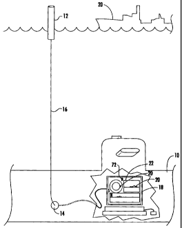
In this invention, long before submarine 10, Fig. 2 reaches periscope depth, 4-
6' long buoy 12 is deployed from launcher 14 of submarine 10, typically a
three inch
counter measure launcher usually used to launch flares and expendable
Bathythermographs (XBTs). Submarine 10 may be an attack class or Trident class
submarine. Buoy 12 is tethered to submarine 10 via cable 16 discussed infra
which
extends through the breech door of the launcher and interconnects buoy 12 with
workstation 18 on board submarine 10.
CA 02454097 2004-01-16
WO 03/012469 PCT/US02/21517
7
Deployment of expendable photonic buoy 12 begins with the loading of the
buoy in the submarine's existing countermeasure launcher 14. The fiber-optic
cable
16 used to connect the buoy to imaging workstation 18 is fed through the
breech door
of the launcher and connected to imaging workstation 18. Following the launch,
expendable photonic buoy 12 floats to the surface while paying out the fiber-
optic
cable. Once the buoy has reached the surface, panoramic imagery (including
surface
ship 20) captured by the camera in buoy 12 is transmitted over the fiber-optic
cable to
imaging workstation 18. Using imaging workstation 18, the operator has the
ability to
observe the video imagery, capture still-frame images and to mark contacts as
shown
at 22. Orientation of the video imagery relative to North is determined using
an on-
board flux gate compass. While the buoy is in use, submarine 10 is free to
maneuver
while paying out cable from its own spool of fiber-optic cable remaining in
launcher
14. Disposal of photonic buoy 12 is accomplished by allowing the buoy to
scuttle
itself at the end of an operator selectable duration through the use of a
dissolvable
plug.
Accordingly, photonic buoy 12, Fig. 3 includes lengthy cylindrical 4' long
hull
30 made of aluminum, for example, which can withstand pressures of 200 psi at
a 200
fft launch depth. Hu1130 is divided into two sections or portions: ballast
portion 32
which resides below waterline 34 and top portion 36 which is disposed 1'/2-2'
above
waterline 34. Buoy 12 includes optical bench 38 at top portion 36 configured
to
provide a panoramic view of the horizon as shown at 40, typically 40 above
and 20
below horizontal as shown. Transmission cable 16 transmits video signals to a
remote
location such as workstation 18, Fig. 2 on board submarine 10. In other
embodiments,
however, buoy 12, Fig. 3 can be anchored and used for surveillance purposes
and
CA 02454097 2004-01-16
WO 03/012469 PCT/US02/21517
8
remote communications accomplished by including a transmitter or the like on
buoy
12. Applications include surveillance of sensitive maritime environments,
(e.g., coral
reefs, endangered species habitats, and the like), drug interdiction,
surveillance of
offshore commercial ventures such as pearl farms and oil platforms, and
surveillance
of private waterfront properties. The photonic buoy may include other types of
known
sensors such as acoustic and radio frequency sensors, may include a satellite
up-link to
provide a communications channel to workstation 18, and can be programmed to
provide continuous photographic surveillance to thereby provide photographic
evidence for identification and prosecution purposes.
Optical bench 38, Fig. 3 and 38', Fig. 4 include an optical element configured
to direct a panoramic view of the horizon to an imager. In one embodiment,
optical
bench 38, Fig. 3 includes 45 conical mirror 50 inside top portion 36 of buoy
12
surrounded by and sealed with respect transparent glass cylinder wall 54.
Conical
mirror 50 may be 10mm in diameter and aluminum coated '$ wave. Vertically
oriented imager 56 (e.g., a single board color video CCD camera, NTSC format
768 x
494 resolution) is aimed at conical mirror 52. In some embodiments, imager 56
may
be an infrared camera for nighttime surveillance or two cameras may be used, a
CCD
video camera and also an infrared camera.
In another embodiment, optical bench 38, Fig. 4 of buoy 12' includes conical
prism 60 sealed with respect to the top of hul130' as shown and thus a
transparent
cylinder portion is not required in the hull of buoy 12'.
In both embodiments, the other primary components associated with the
photonic buoy of this invention are the same or similar and therefore Figs. 3
and 4 use
the same reference numbers.
CA 02454097 2007-09-26
9
Sensor 70 in hull 30, typically a flux gate compass, detects the attitude of
buoy
12 to provide orientation information of the video imagery relative to North
to
workstation 18, Fig. 2 via transmission cable 14 as shown at 72. In the
preferred
embodiment, cable 14 includes optical fibers and thus buoy 12, Figs. 3 and 4
includes
converter 80 which converts image data captured by camera 56 to optical data
which
is transmitted over the optical fibers in cable 14 connected to converter 80
as shown at
82. In one example, converter 80 is a NTSC to fiber encoder/decoder available
from
the Blackbox Corporation under the trade name "FiberPathTM".
Power source 90 (e.g., a 12 volt battery) provides power for converter 82,
compass 70, and camera 56.
Ballast portion 32 of buoy 12 typically includes weight 90 and cable spool 92
disposed below bulkhead 94. Self scuttling plug 96 dissolves or erodes after a
predetermined time period in water and thus hull portion 32 fills with water
and buoy
12 sinks.
Workstation station 18, Fig. 5 includes display 100 and image stabilization
circuitry for presenting one or more composite images 102, 104, and 106 of the
horizon as imaged by camera 56, Figs. 3-4 through a conical mirror 52, Fig. 3
or
conical prism 60, Fig. 4 or any other suitable optical element configured to
direct a
panoramic view of the horizon to camera 56. The image stabilization circuitry
typically includes frame rate image processing software and hardware such as
the
DataCubeTM (Danvers, MA) MAX PCITM board set (INTEL/PCI) which supports frame
capture and frame-rate image processing (8 x 8 convolution, frame averaging
and
LUT operations). In each image, ship 20 (see Fig. 2) is shown in a stable
fashion even
when waves are present on the ocean surface due to the use of pixel mosaic
software
CA 02454097 2004-01-16
WO 03/012469 PCT/US02/21517
operating on work station 18 which stitches together a stable composite image.
Compensation of buoy motion artifacts due to waves is also accomplished by
capturing still frame images while the buoy is located at the peak of a wave -
a feature
which further boosts the height of optical bench 38, Figs. 3-4 above the
waterline to
increase to observable range.
As such, buoy 12 does not typically include any complex, expensive, and, in
the prior art, ineffective gyro-stabilization optics assemblies. Instead,
workstation 18,
Fig. 5 overcomes the effect of wave motion on the video signal output by the
camera
on the buoy.
Moreover, the use of flux gate compass 70, Figs. 3-4 provides orientation
information to workstation 18, Fig. 5 which determines each contact's bearing
measured in the pixel space.
Also shown in Fig. 5 is spool 1201ocated in launcher 14 for paying out
transmission cable 16 as the submarine moves after launching the buoy.
Although
launcher 14 has been described as a standard three inch launcher and thus buoy
12 is
typically three inches in diameter or less and 4' long, other launchers can be
used
and/or launcher 14 can be fitted with a breech door adapter to allow for a
longer, 6'
long buoy. Spool 92, Figs. 3-4 on buoy 12 typically contains over 200' of
transmission cable while spool 120, Fig. 5 contains up to 1'/z miles of
transmission
cable.
Compared to the prior art attempt to produce a camera type buoy, no gyro-
stabilization optics are required on board buoy 12, Figs. 3-4 and, as such,
optical
bench 38, Figs. 3-4 is higher above the waterline to capture a panoramic view
of the
horizon and image stabilization is provided by workstation 18, Fig. 5. By
using
CA 02454097 2007-09-26
11
optical communications, transmission cable 16 can be very long as compared to
the
short copper wire tether proposed in the prior art.
The use of conical mirror 52, Fig. 3 (or prism 60, Fig. 4) provides a
panoramic
view of the horizon without the use of moving components. The use of imaging
workstation 18, Fig. 5 allows the viewing of the resulting imagery either in
raw form
(as a toroid) showing the whole of the horizon with "up" at the circumference
of the
plot as shown at 106 or as processed to present the user with a vertically
oriented
image to emulate the imagery displayed by existing submarine periscopes as
shown at
102 and 104. The use of camera 56, Figs. 3-4 primarily as an image capture
device
for still frame imagery uses wave motion as an advantage in gaining height-of-
eye (the
height of optical bench 38) above the waterline. Frame rate image processing
supported by the reuse of previously developed photonics mast workstation
software
advantageously resides on workstation 18.
Once buoy 12 is on the surface, roughly 2-3 feet of the buoy will be exposed.
This mimics the typical exposure for existing periscopes when used for an
initial
safety sweep. The range of detection for trawlers (having a 65 foot mast head
height)
is in the range of 5 nautical miles. Large surface contacts having a 100 foot
mast head
height are detectable out to 10 nautical miles.
In this way, photonic buoy 12, Figs. 2-4 prevents collisions and also the
detection of a submarine by enemy ships. Gyro-stabilized optics assemblies are
not
required for image stabilization and the buoy system still provides the user
with an
image stabilized panoramic view of the horizon. The long transmission cable
tether
allows the submarine to maneuver freely even when the photonic buoy is
deployed
and allows the photonic buoy to be deployed even when the submarine is fairly
deep
CA 02454097 2004-01-16
WO 03/012469 PCT/US02/21517
12
below the ocean surface.
A stable composite image representing a panoramic view of the horizon is
provided without the use of an expensive gyro-stabilized optics assembly.
Instead, the
optical bench at the top portion of the buoy includes a vertically oriented
imager
aimed at a panoramic optical element such as a conical mirror or a conical
prism. The
buoy rotates, bobs, and moves to and from in the waves but the remote
workstation
located on board the submarine or elsewhere is configured to compensate for
all
motion artifacts, to capture still frame images, and to stitch together a
stable
composite image. The bearing of any detected watercrafft is provided by the
flux gate
compass on the buoy.
Although specific features of the invention are shown in some drawings and
not in others, this is for convenience only as each feature may be combined
with any
or all of the other features in accordance with the invention. The words
"including",
"comprising", "having", and "with" as used herein are to be interpreted
broadly and
comprehensively and are not limited to any physical interconnection. Moreover,
any
embodiments disclosed in the subject application are not to be taken as the
only
possible embodiments.
Other embodiments will occur to those skilled in the art and are within the
following claims:
What is claimed is: