Language selection

Search

Patent 2454343 Summary

Third-party information liability

Some of the information on this Web page has been provided by external sources. The Government of Canada is not responsible for the accuracy, reliability or currency of the information supplied by external sources. Users wishing to rely upon this information should consult directly with the source of the information. Content provided by external sources is not subject to official languages, privacy and accessibility requirements.

Claims and Abstract availability

Any discrepancies in the text and image of the Claims and Abstract are due to differing posting times. Text of the Claims and Abstract are posted:

  • At the time the application is open to public inspection;
  • At the time of issue of the patent (grant).
(12) Patent: (11) CA 2454343
(54) English Title: COMPOSITE COMPONENT INTEGRATION PANEL
(54) French Title: PANNEAU D'INTEGRATION DE COMPOSANTS COMPOSITES
Status: Expired
Bibliographic Data
(51) International Patent Classification (IPC):
  • B62D 25/08 (2006.01)
  • B60K 11/04 (2006.01)
  • B62D 29/00 (2006.01)
  • B62D 29/02 (2006.01)
  • B62D 29/04 (2006.01)
  • B62D 65/00 (2006.01)
(72) Inventors :
  • HENDERSON, JACK V. (United States of America)
  • HOUTARI, KEIJO J. (United States of America)
  • SCHULTZ, JOHN (United States of America)
  • CHUBA, CHARLES JOHN (United States of America)
(73) Owners :
  • DECOMA INTERNATIONAL INC. (Canada)
(71) Applicants :
  • DECOMA INTERNATIONAL INC. (Canada)
(74) Agent: BRANDT, KERSTIN B.
(74) Associate agent:
(45) Issued: 2010-10-12
(86) PCT Filing Date: 2002-07-18
(87) Open to Public Inspection: 2003-01-30
Examination requested: 2007-07-12
Availability of licence: N/A
(25) Language of filing: English

Patent Cooperation Treaty (PCT): Yes
(86) PCT Filing Number: PCT/CA2002/001095
(87) International Publication Number: WO2003/008256
(85) National Entry: 2004-01-19

(30) Application Priority Data:
Application No. Country/Territory Date
60/306,331 United States of America 2001-07-18
60/329,366 United States of America 2001-10-15

Abstracts

English Abstract


A panel assembly (10) is securable to a front end of a motor vehicle for
positioning and securing a plurality of elements thereto. The panel assembly
has a core (22) connectable to the front end of a motor vehicle. A skin (24)
covers the core (22). A component mounting structure is molded to the skin
(24). The component mounting structure is adapted to have the plurality of
elements attached thereto in spaced relation. The panel assembly (10) may be
assembled to the motor vehicle with the plurality of elements secured thereto.


French Abstract

L'invention concerne un ensemble panneau (10) pouvant être fixé à l'extrémité avant d'un véhicule à moteur afin de placer et de fixer une pluralité d'éléments. Ce panneau comporte une âme (22) reliée à l'extrémité avant d'un véhicule à moteur. Une enveloppe (24) recouvre l'âme. Une surface de fixation de composants est moulée dans l'enveloppe. La structure de fixation de composants est conçue de manière à recevoir la pluralité des éléments fixés à cette dernière de manière espacée. L'ensemble panneau (10) peut être assemblé dans le véhicule à moteur avec la pluralité des éléments fixés audit ensemble panneau.

Claims

Note: Claims are shown in the official language in which they were submitted.


Claims

What is claimed is:


1. A panel assembly securable to a front end of a motor vehicle for
positioning
and securing a plurality of elements thereto, said panel assembly comprising:
an upper section defining a length extending between a driver end and a
passenger end;
a lower section extending between an upper driver end and an upper passenger
end, said upper driver and passenger ends fixedly secured to said length of
said upper
section; and
a component mounting structure molded to a skin of said upper and lower
sections, said component mounting structure adapted to have the plurality of
elements
secured thereto in spaced relation such that said panel assembly may be
assembled to
the motor vehicle with the plurality of elements secured to said panel
assembly,
characterized by said upper and lower sections each comprising the molded skin

encapsulating a core and said component mounting structure comprising a flange

extending away from said core.


2. A panel assembly as set forth in claim 1 wherein said skin includes a first
skin
portion and a second skin portion, said first skin portion covers a portion of
said core
and said second skin portion cooperates with said first skin portion,
encapsulating said
core.


3. A panel assembly as set forth in claim 2 wherein said core is fabricated of

balsa wood.


4. A panel assembly as set forth in claim 3 wherein said skin includes carbon
fiber.


6


5. A panel assembly as set forth in claims 2 to 4 wherein said first skin
portion
includes said flange.


6. A panel assembly as set forth in claim 5 wherein said second skin portion
includes said flange.


7. A panel assembly as set forth in claim 6 wherein said upper section
includes
joint connections disposed at said driver end and said passenger end.


8. A panel assembly securable to a front end of a motor vehicle for
positioning
and securing a plurality of elements thereto, said panel assembly comprising:
an upper section defining a length extending between a driver end and a
passenger end;
a lower section extending between an upper driver end and an upper passenger
end, said upper driver and passenger ends fixedly secured to said length of
said upper
section; and
a component mounting structure molded to said upper and lower sections, said
component mounting structure adapted to have the plurality of elements secured

thereto in spaced relation such that said panel assembly may be assembled to
the
motor vehicle with the plurality of elements secured to said panel assembly,
characterized by said upper and lower sections each comprising a molded skin
encapsulating a core.


9. A panel assembly as set forth in claim 8 wherein said skin includes a first
skin
portion and a second skin portion, said first skin portion covers a portion of
said core
and said second skin portion cooperates with said first skin portion,
encapsulating said
core.


10. A panel assembly as set forth in claim 9 wherein said core is fabricated
of
balsa wood.


7


11. A panel assembly as set forth in claim 10 wherein said skin includes
carbon
fiber.


12. A panel assembly as set forth in claim 11 wherein said upper section
includes
joint connections disposed at said driver end and said passenger end.


8

Description

Note: Descriptions are shown in the official language in which they were submitted.


CA 02454343 2004-O1-19
WO 03/008256 PCT/CA02/01095
COMPOSITE COMPONENT INTEGRATION PANEL
Field of the Invention
The invention relates to a composite component integration panel for an
automotive vehicle. More particularly, the invention relates to a front end
assembly
of a motor vehicle that integrates automotive components typically found in a
forward
section of a motor vehicle.
Description of the Related Art
A grille opening reinforcement (GOR) is one of the most important
components of the front end of an automobile. A GOR is a molded piece having a
Class "B" surface, i.e., a surface that is 'not visible when the motor vehicle
is fully
assembled. Components such as fenders, bumper covers, grilles, headlamps and
the
like axe assembled to the GOR. The GOR provides attachments, locators and
structural support to the components that are secured thereto. It also
provides access
for lamp bulb replacement, secondary hood latch release levers, and other
maintenance and repair requirements.
The priri~ary function of a GOR is to provide the assembly plants a controlled
and predictable front-end composite structure for their vehicles. An original
equipment manufacturer (OEM) typically incorporates the GOR into all of its
designs
because the fit and finish of all front-end exterior components are maintained
at a high
level with great precision. However, a disadvantage of GOR designs is that
much of
the structure of the GOR is duplicated by a similar structure, namely, the
radiator
support.
Summary Of The Invention
Accordingly, a panel is provided for front-end structure, crash management,
and attaching components to a front end of a vehicle body. The panel
eliminates
duplication of structure between a conventional radiator structure and the
GOR. The
panel could be installed in either a body shop or trim line application. The
trim line
1
SUBSTITUTE SHEET (RULE 26)


CA 02454343 2004-O1-19
WO 03/008256 PCT/CA02/01095
application would allow for additional component integration: For example,
parts
such as headlamps, park turn lamps, grille, radiator, fascia, fluid
reservoirs, and air
dams could first be assembled to the panel, thus forming a front-end module,
which
would then be attached to the body structure. Therefore, the panel would not
have an
impact on a traditional body shop build but more importantly would have the
flexibility of added part consolidation.
Brief Description Of The Drawings
Advantages of the invention will be readily appreciated as the same becomes
better understood by reference to the following detailed description when
considered
in connection with the accompanying drawings, wherein:
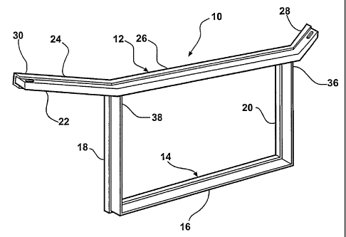
Figure 1 is a perspective view of a first embodiment of the invention;
Figure 2 is a perspective view of the first embodiment of the invention
in complete form;
Figure 3 is a partially cut-away perspective view of the first
embodiment of the invention;
Figure 4 is a partially cut-away perspective view of a second
embodiment of the invention;
Figure 5 is a partially cut-away perspective view of a third
embodiment of the invention;
Figure 6 is a partially cut-away perspective view of a fourth
embodiment of the invention;
Figure 7 is a perspective view of a fifth embodiment of the invention;
and
Figure 8 is a perspective view of the fifth embodiment of the invention
in complete form.
2
SUBSTITUTE SHEET (RULE 26)


CA 02454343 2004-O1-19
WO 03/008256 PCT/CA02/01095
Detailed Description Of The Preferred Embodiments
As shown in the Figures, wherein like primed numerals represent
similar elements in different embodiments, a panel assembly of the present
invention
is generally indicated at 10. The panel assembly 10 is an open structural
frame having
an upper section 12 and a lower section 14. The lower section 14 includes a
cross
member 16 and two side members 18, 20 creating a U-shape. Each of the upper 12
and lower 14 sections has a core 22 and a skin 24. In the preferred
embodiment, the
core 22 is fabricated from balsa wood and the skin 24 is fabricated from a
fiber resin
matrix, such as a carbon fiber. The balsa wood core 22 is inserted into a
mold, which
is subsequently shot with the carbon fiber. The carbon fiber skin 24 is
applied to the
balsa core 22 and serves as a tensile member in impact situations.
The upper section 12 defines a length 26 that extends between a driver
end 28 and a passenger end 30. The length 26 extends through a non-linear path
in
the preferred embodiment. Each of the driver 28 and passenger 30 ends include
joint
connections 32, 34, best seen in Figure 7. The joint connections 32, 34 will
be
discussed in greater detail subsequently.
The lower section 14 extends between an upper driver end 36 and an
upper passenger end 38. More specifically, one 20 of the side members 18, 20
ends at
the upper driver end 36 and the other 18 of the side members 18, 20 ends at
the upper
passenger end 38. The upper driver 36 and passenger 38 ends are fixedly
secured to
the length 26 of the upper section 12 between the driver 28 and passenger 30
ends
thereof.
As detailed in Figure 3, the carbon fiber skin 24 is shaped in a partial
C-section. The C-section allows for increased structural integrity and
facilitates wet
out in the molding process. The carbon fiber skin 24 includes a first skin
portion 40
and a second skin portion 42 that together envelop the core 22. This process
of
manufacture is via molding, as alluded to above.
The panel assembly 10 is inserted into a compression mold, thus
allowing for intricate shapes and attachment features to be molded in a
component
mounting structure 44, shown in Figure 2. After the panel assembly 10 is
inserted in
3
SUBSTITUTE SHEET (RULE 26)


CA 02454343 2004-O1-19
WO 03/008256 PCT/CA02/01095
the tool, a thermoplastic/glass reinforced material fills the mold via a
compression or '
injection molding process. During the molding process, the thermoplastic/glass
reinforced material is essentially in a liquid state, which allows for
complete material
distribution and wet out to the panel assembly 10. These aforementioned
processes
serve two main functions. First, the carbon fiber skin 24 and balsa wood core
22 are
completely encapsulated (box section) with a structural skin 46. Second,
module
formation of the head lamp, fascia, grille, radiator, and body structure
attachments can
be performed away from assembly of a motor vehicle.
Calculations can demonstrate the composite panel's attributes as they
relate to vehicle stiffness and crash worthiness are far superior to steel
structural
counterparts. The mass moment of inertia properties for the panel assembly 10
in the
Z-direction, e.g., the direction of an impact, reap significant magnitudes of
improvement in comparison to the impact directional mass moment of inertia
properties of the steel structure.
A test was performed with the loading criteria input based on a 4500
pound vehicle subject to 40% offset/40 mile per hour deformable barrier
impact. This
test yielded a resultant point load (offset from vehicle centerline) of 50,000
pounds.
Due to the ultimate tensile strength of steel being exceeded by the stress of
the
loading condition, the results yielded a catastrophic failure in the steel
radiator
structure. The comparison of deflection and stresses between the panel
assembly 10
and the steel radiator structure demonstrates that the panel assembly 10 would
significantly improve vehicle stiffness and crash worthiness.
An additional crash energy attribute of the panel assembly 10 is in the
design of the joint connections 32, 34 to the shotgun rails (not shown). The
joint
connections 32, 34, as shown in Figure 7, would hold the shotgun rails of the
motor
vehicle and be attached with a through bolt, thus coupling the two upper
shotgun rails.
Under an offset/high speed crash similar to that discussed above, the coupling
of the
upper shotguns enables the energy due to impact will be dissipated through
each side
of the motor vehicle.
Lastly, relative to energy management, the panel assembly 10 is
advantageous in terms of pedestrian protection (upper leg/lower torso to
grille/hood
4
SUBSTITUTE SHEET (RULE 26)


CA 02454343 2004-O1-19
WO 03/008256 PCT/CA02/01095
impact). These advantages may be attributed to the sandwich construction of
the
panel assembly 10, as it has the ability to distribute local loads and
stresses over a
large area. This equates to a lower HIC (head impact criteria) value upon
pedestrian
impact.
A mass comparison of the panel assembly 10 and the steel radiator
structure for a typical passenger vehicle such as a midsize motor vehicle (a
family
sedan) yielded the following results: the steel radiator structure (upper rail
portion
only) weighed 6.6 pounds in comparison to 5.33 pounds for the panel assembly
10.
The overall approximate weight of the steel radiator structure and panel
assembly 10,
without lamp canisters or integrated air deflectors, are 15.5 and 8.14 pounds,
respectively. Therefore, improvements of energy dissipation are matched by the
reduction in weight to the motor vehicle.
The invention has been described in an illustrative manner. It is to be
understood that the terminology, which has been used, is intended to be in the
nature
of words of description rather than of limitation. Many modifications and
variations
of the invention are possible in light of the above teachings. Therefore,
within the
scope of the appended claims, the invention may be practiced other than as
specifically described.
5
SUBSTITUTE SHEET (RULE 26)

Representative Drawing
A single figure which represents the drawing illustrating the invention.
Administrative Status

For a clearer understanding of the status of the application/patent presented on this page, the site Disclaimer , as well as the definitions for Patent , Administrative Status , Maintenance Fee  and Payment History  should be consulted.

Administrative Status

Title Date
Forecasted Issue Date 2010-10-12
(86) PCT Filing Date 2002-07-18
(87) PCT Publication Date 2003-01-30
(85) National Entry 2004-01-19
Examination Requested 2007-07-12
(45) Issued 2010-10-12
Expired 2022-07-18

Abandonment History

There is no abandonment history.

Payment History

Fee Type Anniversary Year Due Date Amount Paid Paid Date
Application Fee $400.00 2004-01-19
Registration of a document - section 124 $100.00 2004-06-21
Maintenance Fee - Application - New Act 2 2004-07-19 $100.00 2004-06-21
Maintenance Fee - Application - New Act 3 2005-07-18 $100.00 2005-06-14
Maintenance Fee - Application - New Act 4 2006-07-18 $100.00 2006-06-20
Maintenance Fee - Application - New Act 5 2007-07-18 $200.00 2007-06-15
Request for Examination $800.00 2007-07-12
Maintenance Fee - Application - New Act 6 2008-07-18 $200.00 2008-06-18
Maintenance Fee - Application - New Act 7 2009-07-20 $200.00 2009-06-12
Maintenance Fee - Application - New Act 8 2010-07-19 $200.00 2010-06-15
Final Fee $300.00 2010-07-29
Maintenance Fee - Patent - New Act 9 2011-07-18 $200.00 2011-06-14
Maintenance Fee - Patent - New Act 10 2012-07-18 $250.00 2012-06-26
Maintenance Fee - Patent - New Act 11 2013-07-18 $250.00 2013-06-12
Maintenance Fee - Patent - New Act 12 2014-07-18 $250.00 2014-06-25
Maintenance Fee - Patent - New Act 13 2015-07-20 $250.00 2015-06-24
Maintenance Fee - Patent - New Act 14 2016-07-18 $250.00 2016-06-22
Maintenance Fee - Patent - New Act 15 2017-07-18 $450.00 2017-06-21
Maintenance Fee - Patent - New Act 16 2018-07-18 $450.00 2018-06-27
Maintenance Fee - Patent - New Act 17 2019-07-18 $450.00 2019-06-26
Maintenance Fee - Patent - New Act 18 2020-07-20 $450.00 2020-06-24
Maintenance Fee - Patent - New Act 19 2021-07-19 $459.00 2021-06-24
Owners on Record

Note: Records showing the ownership history in alphabetical order.

Current Owners on Record
DECOMA INTERNATIONAL INC.
Past Owners on Record
CHUBA, CHARLES JOHN
HENDERSON, JACK V.
HOUTARI, KEIJO J.
SCHULTZ, JOHN
Past Owners that do not appear in the "Owners on Record" listing will appear in other documentation within the application.
Documents

To view selected files, please enter reCAPTCHA code :


To view images, click a link in the Document Description column. To download the documents, select one or more checkboxes in the first column and then click the "Download Selected in PDF format (Zip Archive)" or the "Download Selected as Single PDF" button.

List of published and non-published patent-specific documents on the CPD .

If you have any difficulty accessing content, you can call the Client Service Centre at 1-866-997-1936 or send them an e-mail at CIPO Client Service Centre.


Document
Description 
Date
(yyyy-mm-dd) 
Number of pages   Size of Image (KB) 
Abstract 2004-01-19 2 67
Claims 2004-01-19 1 47
Description 2004-01-19 5 234
Drawings 2004-01-19 3 84
Representative Drawing 2004-01-19 1 10
Cover Page 2004-03-16 1 42
Representative Drawing 2010-09-14 1 12
Cover Page 2010-09-14 1 45
Claims 2009-12-01 3 78
PCT 2004-01-19 10 345
Assignment 2004-01-19 3 95
Correspondence 2004-03-11 1 34
Correspondence 2004-03-25 3 88
PCT 2004-01-19 1 7
Correspondence 2007-08-29 1 16
Prosecution-Amendment 2009-12-01 5 138
Assignment 2004-06-21 4 131
Assignment 2004-01-19 6 183
Prosecution-Amendment 2007-07-12 1 27
Correspondence 2007-07-12 2 44
Prosecution-Amendment 2008-06-25 1 30
Prosecution-Amendment 2009-06-08 2 40
Correspondence 2010-07-29 1 29