Note: Descriptions are shown in the official language in which they were submitted.
CA 02454577 2004-O1-20
WO 03/009646 PCT/US02/22878
MICROWAVE DESORBER
BACKGROUND OF THE INVENTION
Related Applications
This application claims priority from U.S. Provisional Patent Application No.
60/306,816, filed July 20, 2001 and entitled "Microwave Desorber".
Field of the Invention
This invention relates generally to methods and apparatus for drying
materials, and
more specifically to microwave apparatus for removing volatile organic
compounds from
resins.
Discussion of the Prior Art
Microwaves have been used for many years to remove substances from various
materials. In many cases this has occurred in dryers where moisture has been
removed from
the material using microwave energy.
More recently, microwaves have been used to remove volatile organic compounds
(VOCs) from resins onto which the VOCs have been adsorbed. In this context the
microwave energy is very effective in selectively heating most VOCs. The resin
will also
heat up to some degree because it is not completely transparent to the
microwave energy.
With these two heat sources, the VOCs tend to volatilize thereby cleaning the
resins for
subsequent use, for example in a continuous process.
In some cases, a large container having a diameter such as 24 inches has been
filled
with the contaminated resins. A stationary waveguide has been positioned along
the axis of
the container and suitably aperatured to release the microwave energy radially
outwardly into
the resin. In theory, the VOCs are volatized and thereby removed from the
resins. A vacuum
pump can be used to draw the VOCs from the resin and out of the vessel in
either a batch or
CA 02454577 2004-O1-20
WO 03/009646 PCT/US02/22878
continuous process for treating the resin. Unfortunately, it has been found
that the heat
distribution within the large container varies significantly producing both
hot spots and cold
spots throughout the container. At the hot spots, the VOCs are released from
the resin, but at
the cold spots, these released VOCs are merely adsorbed back onto the resins.
As a result, a
relatively low efficiency results requiring considerable time and energy to
clean the resin
batch. Processes in which the resin flows continuously through the desorber
vessel, also
suffer, but to a lesser degree, because of the time averaging effect of moving
the resin
through a certain temperature profile or distribution.
SUMMARY OF THE INVENTION
In accordance with the present invention, the waveguide along the axis of the
container is moved relative to the container. As a result, the microwave
energy is more
uniformly distributed throughout the container. This relative movement will
generally result
as the waveguide is moved axially back and forth within a stationary
container. The
waveguide may also be oscillated and/or rotated on the axis of the container
to produce this
relative movement. Of course the container could also be moved relative to a
stationary
waveguide to produce a heat pattern which is more uniformed.
It has been found that temperature distributions vary radially within a
cylindrical
cavity. This distribution can be experimentally or theoretically calculated
and an optimal
radial section can be chosen for a particular microwave load. By placing the
resin within this
zone or otherwise passing the resin through this zone, more uniform heat
distribution will
result in a much higher efficiency and require less time to clean the resins.
In one aspect, the invention relates to a system for removing contaminants
adsorbed
onto a resin. A container is provided to receive the contaminated resin. At
least one
waveguide having an axis is disposed within the container and adapted to
introduce
microwave energy into the contaminated resins in the container. A mechanism is
provided
for moving one of the container and the waveguide relative to the other of the
container and
the waveguide to facilitate uniform heating of the contaminated resin in the
container. This
relative movement can result from movement of one or both of the container and
waveguide.
The movement may be axial or radial and will typically be an oscillating
movement.
2
CA 02454577 2004-O1-20
WO 03/009646 PCT/US02/22878
In another aspect of the invention, the container has an outer wall, and the
waveguide
has an inner wall. At least one zone wall is disposed between the inner wall
and the outer
wall, and defines a preferred zone within the container where optimum heating
characteristics
S occur for separating the contaminants from the resin. The zone wall can be
formed from a
low loss material having microwave transmission characteristics greater than
that of a metal.
A second zone wall can be disposed between the first zone wall and the outer
wall of the
container. In this case, the preferred zone is spaced from the inner wall of
the waveguide and
the outer wall of the container.
In an additional aspect, the invention includes a method for removing
contaminants
adsorbed onto a resin. This method includes the steps of providing a container
to receive the
contaminated resin, and positioning at least one waveguide within the
container. Microwave
energy is introduced through the waveguide into the contaminated resin to heat
the
contaminants. This method also includes the step of moving one of the
container and the
waveguide relative to the other of the container and the waveguide to
facilitate heating of the
contaminant during the heating step.
In a further aspect of the invention, a method for removing contaminants
adsorbed
onto a resin includes the step of defining a preferred zone in the container
between the outer
wall of the container and the inner wall of the waveguide. This preferred zone
has optimal
heating characteristics for heating the contaminant. After the contaminants
have been heated
to separate them from the resin, the contaminants can be removed from the
preferred zone.
These and other features and advantages of the invention will become more
apparent
with a description of the preferred embodiments of the invention with
reference with the
associated drawings.
CA 02454577 2004-O1-20
WO 03/009646 PCT/US02/22878
DESCRIPTION OF THE DRAWINGS
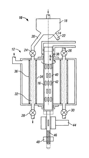
FIG. 1 is an axial cross-section view of one embodiment of the present
invention
including a container and microwave waveguide, with contaminated resin
positioned in an
optimum zone to facilitate heating of the contaminants;
FIG. 2 is a cross-sectional view taken along lines 2 - 2 of FIG. 1 and
illustrating a
preferred relative disposition of inlet and outlet valves; and
FIG. 3 is a perspective view of the microwave waveguide illustrated in FIGS. 1
and 2.
DESCRIPTION OF THE PREFERRED EMBODIMENTS AND
BEST MODE OF THE INVENTION
The system of the present invention is illustrated in Figure 1 and designated
by the
reference numeral 10. This system includes a container 12 having an axis 14. A
waveguide
16, which receives microwave energy from a generator (not shown), is disposed
along the
axis 14. A resin hold tank 18 receives contaminated resin from an adsorber
(not shown) and
introduces this load through two or more delivery lines such as those
designated by reference
numerals 20 and 22. These delivery lines 20 and 22 are connected through inlet
valves 24
and 26 to introduce the contaminated resin into the container 12. Similar
outlet valves 28 and
are provided at the output of the container 12 to direct the clean resin back
to the adsorber
(not shown). Between the inlet valves 24 and 26, and the outlet valves 28, 30,
the
contaminated resin is exposed to microwave energy within the container 12
which drives off
25 the VOCs. Vacuum is applied to the vessel to extract these volatilized
gases. A radial flow
of nitrogen or other inert purge gas can be used in conjunction with the
vacuum.
In the interest of obtaining a more even distribution of heat within the
container 12, a
particular radial zone 32 is chosen where the heat is most evenly distributed.
This zone 32
30 will typically exist between two concentric cylinders which provide the
zone 32 with a
cylindrical configuration. These cylinders are preferably formed from low loss
materials,
such as ceramics and fiberglass, which are generally transparent to microwave
radiation.
4
CA 02454577 2004-O1-20
WO 03/009646 PCT/US02/22878
These materials permit more of the microwaves to heat the VOCs first from the
direct
application of energy from the waveguide 16, and second from the energy
reflected back
from the walls of the container 12.
In this embodiment, the inner cylinder defining the zone 32 will typically
have a wall
34 with a diameter Dl typically greater than the diameter of the waveguide 16.
The outer
cylinder defining the zone 32 will have a wall 36 with a diameter D2 typically
less than that
of the container 12. The diameter D 1 will be less than the diameter D2. For
example, in a
preferred embodiment, the waveguide 16 may have a diameter of four inches
while the
container 12 has a diameter of 24 inches. The inside diameter D 1 of the zone
32 is twelve
inches while the outside diameter D2 of the zone 32 is nineteen inches. In
this particular case
the zone 32 is formed as a cylinder having an inside radius of four inches
from the waveguide
16 and an outside radius extending to within 2'/Z inches from the outer wall
of the container
12. Within the 3 %2 inch radius of the zone 32, the contaminated resin is
received at the top
through the inlet valves 24 and 26, is cleaned within the uniform temperature
of the zone 32,
and the clean resins are metered through the outlet valves 28 and 30.
Further heat uniformity can be obtained in the zone 32 by moving the waveguide
16
relative to the container 12 and the zone 32. In a preferred embodiment, this
relative
movement is produced by oscillating the waveguide 16 axially up and down as
shown by the
arrow 38. The length of the oscillation will typically depend on the
configuration of the slots
within the waveguide. Generally slots, such as those designated by the
reference numerals 40
and 42 are provided to disperse the energy from the waveguide 16. Typically
these slots 40,
42 are vertically disposed and separated center-to-center by a distance of
about one half or
one wavelength. Groups of slots are also equally spaced around the
circumference of the
waveguide. Vertical movement of the waveguide 16 in a preferred embodiment is
set for a
total travel equivalent to the vertical distance end-to-end between the slots,
such as the slots
40, 42. A motor 44 in combination with a ball screw 46 and nut 48 can be
coupled to the
waveguide 16 and operated to produce the axially oscillations.
Further relative movement between the waveguide 16 and the container 12 can be
provided by rotating the waveguide 16 relative to the zone 32. This can be a
continuous
rotation or an oscillating rotation caused by the motor 44. A top plan view of
the system 10
S
CA 02454577 2004-O1-20
WO 03/009646 PCT/US02/22878
is illustrated in Figure 2 and taken along the lines 2-2 of Figure 1. In this
plan view, it can be
seen that the inlet valves 24 and 26 can be diametrically opposed and
angularly spaced by up
to 90° from the outlet valves 28 and 30. The other two inlet valves
(not shown) and exit
valves (not shown) can be similarly spaced to facilitate a good flow and
mixture of the
contaminated resins within the zone 32.
A perspective view of the waveguide 16 is illustrated by itself in Figure 3
and shows
in greater detail the relationship of the slots 40 and 42 with respect to the
waveguide 16 and
associated ball screw 46.
From the foregoing discussion it will be apparent that more uniform heating
can be
achieved in two ways: 1 ) determining the radial zone having the greatest
uniformity of heat
disposition, and 2) moving the source of the microwaves relative to the load.
In this second
case, relative movement is required but that movement can occur with the
waveguide 16
moving relative to a stationary container 12 or the container 12 moving
relative to a
stationary waveguide 16. In all cases, even heat distribution within the load
is the ultimate
goal. The specific dimensions and placement of parts may vary with the type of
load, such as
the type of resin or the type of material contaminating the load. These and
other features and
advantages will now be apparent to a person of ordinary skill in the art
pertaining to this
invention.
From the foregoing description of preferred embodiments it will be apparent
that
many of the advantages associated with the present invention can be achieved
without
departing from the spirit and scope of the invention. Therefore, it must be
understood that the
illustrated embodiments have been set forth only for the purposes of example
and should not
be taken as limiting the invention. Accordingly, one is cautioned not to limit
the concept
only to those embodiments disclosed, but rather to determine the scope of the
invention only
with reference to the following claims.
6