Note: Descriptions are shown in the official language in which they were submitted.
CA 02454607 2007-07-19
TITLE OF THE INVENTION
SYSTEM AND METHOD FOR PATIENT TEMPERATURE CONTROL
EMPLOYING TEMPERATURE PROJECTION ALGORITHM
FIELD OF THE INVENTION
The present invention relates generally to the
lowering, raising, and control of the temperature of
the human body. More particularly, the invention
relates to a method and intravascular apparatus for
controlling the temperature of the human body.
BACKGROUND
Background Information - Organs in the human
body, such as the brain, kidney and heart, are
maintained at a constant temperature of approximately
370 C. Hypothermia can be clinically defined as a
core body temperature of 35 C or less. Hypothermia
is sometimes characterized further according to its
severity. A body core temperature in the range of 33
C to 35 C is described as mild hypothermia. A body
temperature of 28 C to 32 C is described as moderate
hypothermia. A body core temperature in the range of
24 C to 28 C is described as severe hypothermia.
Hypothermia is uniquely effective in reducing
ischemia. For example, it is effective in reducing
brain injury caused by a variety of neurological
Page 1
CA 02454607 2007-07-19
insults and may eventually play an important role in
emergency brain resuscitation. Experimental evidence
has demonstrated that cerebral cooling improves
outcome after global ischemia, focal ischemia, or
traumatic brain injury. For this reason, hypothermia
may be induced in order to reduce the effect of
certain bodily injuries to the brain as well as
ischemic injuries to other organs.
Page 2
CA 02454607 2007-07-19
SiJNIIMARY OF THE INVENTION
The apparatus of the present invention can
include a heat transfer element which can be used to
apply cooling to the blood flowing in a vessel. The
heat transfer element, by way of example only,
comprises first and second elongated, articulated
segments, each segment having a turbulence-inducing
exterior surface. A flexible joint can connect the
first and second elongated segments. An inner coaxial
lumen may be disposed within the first and second
elongated segments and is capable of transporting a
working fluid to a distal end of the first elongated
segment. In addition, the first and second elongated
segments may have a turbulence-inducing interior
surface for inducing turbulence within the pressurized
working fluid. The turbulence-inducing exterior
surface may be adapted to induce turbulence within a
free stream of blood flow when placed within an artery
or vein. The turbulence-inducing exterior surface may
be adapted to induce a turbulence intensity greater
than 0.05 within a free stream blood flow. In one
embodiment, the flexible joint comprises a bellows
section which also allows for axial compression of the
heat transfer element.
In an embodiment, the turbulence-inducing
exterior surfaces of the heat transfer element
comprise one or more helical ridges. Adjacent
Page 3
CA 02454607 2007-07-19
segments of the heat transfer element can be
oppositely spiraled to increase turbulence. For
instance, the first elongated heat transfer segment
may comprise one or more helical ridges having a
counter-clockwise twist, while the second elongated
heat transfer segment comprises one or more helical
ridges having a clockwise twist. Alternatively, of
course, the first elongated heat transfer segment may
comprise one or more clockwise helical ridges, and the
second elongated heat transfer segment may comprise
one or more counter-clockwise helical ridges. The
first and second elongated, articulated segments may
be formed from highly conductive materials.
The heat transfer device may also have a coaxial
supply catheter with an inner catheter lumen coupled
to the inner coaxial lumen within the first and second
elongated heat transfer segments. A working fluid
supply configured to dispense the pressurized working
fluid may be coupled to the inner catheter lumen. The
working fluid supply may be configured to produce the
pressurized working fluid at a temperature of about
0 C and at a pressure below about 5 atmospheres of
pressure. The working fluid may be ISOLYTE , saline,
D5W, etc.
In yet another alternative embodiment, the heat
transfer device may have three or more elongated,
articulated, heat transfer segments having a
turbulence-inducing exterior surface, with additional
Page 4
CA 02454607 2007-07-19
flexible joints connecting the additional elongated
heat transfer segments. In one such embodiment, by
way of example, the first and third elongated heat
transfer segments may comprise clockwise helical
ridges, and the second elongated heat transfer segment
may comprise one or more counter-clockwise helical
ridges. Alternatively, of course, the first and third
elongated heat transfer segments may comprise counter-
clockwise helical ridges, and the second elongated
heat transfer segment may comprise one or more
clockwise helical ridges.
The turbulence-inducing exterior surface of the
heat transfer element may optionally include a surface
coating or treatment to inhibit clot formation.
The present invention also envisions a method of
cooling the body which comprises inserting a flexible,
conductive cooling element into the inferior vena cava
from a distal location, and providing a means of
warming the body to prevent shivering by means of a
cooling blanket. The method further includes
circulating a working fluid through the flexible,
conductive cooling element in order to lower the
temperature of the body. The flexible, conductive
heat transfer element absorbs more than about 25, 50
or 75 Watts of heat.
The method may also comprise inducing turbulence
within the free stream blood flow within an artery or
vein. In one embodiment, the method includes the step
Page 5
CA 02454607 2007-07-19
of inducing blood turbulence with a turbulence
intensity greater than about 0.05 within the vascular
system. The circulating may comprise inducing mixing
flow of the working fluid through the flexible,
conductive heat transfer element. The pressure of the
working fluid may be maintained below about 5
atmospheres of pressure.
The cooling or warming may comprise circulating a
working fluid in through an inner lumen in the
catheter and out through an outer, coaxial lumen. In
one embodiment, the working fluid remains a liquid
throughout the cycle. The working fluid may be
aqueous.
The present invention also envisions a cooling or
warming catheter comprising a catheter shaft having
first and second lumens therein. The catheter also
comprises a cooling or warming tip adapted to transfer
heat to or from a working fluid circulated in through
the first lumen and out through the second lumen, and
turbulence-inducing structures on the tip capable of
inducing free stream turbulence when the tip is
inserted into a blood vessel. The tip may be adapted
to induce turbulence within the working fluid. The
catheter is capable of removing at least about 25
Watts of heat from an organ when inserted into a
vessel supplying that organ, while cooling the tip
with a working fluid that remains a liquid in the
catheter. Alternatively, the catheter is capable of
Page 6
CA 02454607 2007-07-19
removing at least about 50 or 75 Watts of heat from an
organ when inserted into a vessel supplying that
organ, while cooling the tip with an aqueous working
fluid.
In another embodiment, a cooling or warming
catheter may comprise a catheter shaft having first
and second lumens therein, a cooling or warming tip
adapted to transfer heat to or from a working fluid
circulated in through the first lumen and out through
the second lumen, and turbulence-inducing structures
on the tip capable of inducing turbulence when the tip
is inserted into a blood vessel.
The present invention may also provide a
temperature control apparatus comprising a flexible
catheter which can be inserted through the vascular
system of a patient to an artery or vein, with an
inflatable balloon heat exchanger near the distal end
of the catheter. The present invention also
encompasses a method for using such a device to
perform cooling, heating, or temperature management.
After placement in a vessel, an embodiment of the
invention includes an apparatus where the heat
exchanger balloon is inflated by pressurization with a
working fluid, such as saline, ISOLYTEO, D5W, or other
similar fluids, or combinations of these, via a supply
lumen in the catheter. The heat exchanger balloon has
one or more blood passageways passing through it, from
a proximal aspect of the balloon to a distal aspect of
Page 7
CA 02454607 2007-07-19
the balloon. When the heat exchanger balloon is
inflated to contact the wall of the artery in which it
is placed, each of the blood passageways comprises a
tube having an inlet in one face of the heat exchanger
balloon and an outlet in another face of the heat
exchanger balloon, thereby allowing blood to continue
flowing through the artery after inflation of the
balloon. The blood passageway tubes can be
constructed of a material having a relatively high
thermal conductivity, such as a thin metallized
polymer, such as a film with one or more metallized
surfaces. Alternatively, the blood passageway tubes
can be constructed of a metal-loaded polymer film.
Further, the entire heat exchanger balloon can be
constructed of such a material, in order to maximize
the cooling capacity of the heat exchanger.
After inflation of the heat exchanger balloon,
the saline solution, which is chilled by an external
chiller, continues circulating through the interior of
the heat exchanger balloon, around the blood
passageway tubes, and back out of the balloon through
a return lumen in the catheter. This cools the blood
passageway tubes, which in turn cool the blood flowing
through them. This cooled blood then flows through
the selected organ and cools the organ.
The device can also incorporate a lumen for a
guidewire, facilitating the navigation of the catheter
through the vascular system of the patient.
Page 8
CA 02454607 2007-07-19
In one aspect, the invention is directed to
a catheter system to change the temperature of blood
by heat transfer to or from a working fluid. The
system includes an inflatable inlet lumen and outlet
lumen. The outlet lumen is coupled to the inlet lumen
so as to transfer working fluid between the two. The
outlet lumen has a structure when inflated to induce
turbulence in the blood and/or in the working fluid.
Variations of the system may include one or more
of the following. The inlet lumen and the outlet
lumen may be made of a flexible material such as latex
rubber. The outlet lumen may have a structure to
induce turbulence in the working fluid when inflated,
such as a helical shape which may be tapered in a
segmented or non-segmented manner. The radii of the
inlet and outlet lumens may decrease in a distal
direction such that the inlet and outlet lumens are
tapered when inflated. A wire may be disposed in the
inlet or outlet lumens to provide shape and strength
when deflated.
The thickness of the outlet lumen, when inflated,
may be less than about 1-~ mil. The length of the
inlet lumen may be between about 5 and 30 centimeters.
If the outlet lumen has a helical shape, the diameter
of the helix may be less than about 8 millimeters when
inflated. The outer diameter of the helix of the
outlet lumen, when inflated, may be between about 2
millimeters and 8 millimeters and may taper to between
Page 9
CA 02454607 2007-07-19
about 1 millimeter and 2 millimeters. In segmented
embodiments, a length of a segment may be between
about 1 centimeter and 10 centimeters. The radii of
the inlet and outlet lumens when inflated may be
between about 0.5 millimeters and 2 millimeters.
The outlet lumen may further include at least one
surface feature and/or interior feature, the surface
feature inducing turbulence in the fluid adjacent the
outlet lumen and the interior feature inducing
turbulence in the working fluid. The surface feature
may include one or more helical turns or spirals
formed in the outlet lumen. Adjacent turns may employ
opposite helicity. Alternatively or in combination,
the surface feature may be a series of staggered
protrusions formed in the outlet lumen.
The turbulence-inducing outlet lumen may be
adapted to induce turbulence when inflated within a
free stream of blood when placed within an artery. The
turbulence intensity may be greater than about 0.05.
The turbulence-inducing outlet lumen may be adapted to
induce turbulence when inflated throughout the period
of the cardiac cycle when placed within an artery or
during at least 20% of the period.
The system may further include a coaxial supply
catheter having an inner catheter lumen coupled to the
inlet lumen and a working fluid supply configured to
dispense the working fluid and having an output
coupled to the inner catheter lumen. The working
Page 10
CA 02454607 2007-07-19
fluid supply may be configured to produce a
pressurized working fluid at a temperature of between
about -3 C and 36 C and at a pressure below about 5
atmospheres of pressure. Higher temperatures may be
employed if blood heating is desired.
The turbulence-inducing outlet lumen may include
a surface coating or treatment such as heparin to
inhibit clot formation. A stent may be coupled to the
distal end of the inlet lumen. The system may be
employed to cool or heat volumes of tissue rather than
blood.
In embodiments employing a tapered helical outlet
lumen, the taper of the outlet lumen allows the outlet
lumen to be placed in an artery having a radius less
than the first radius. The outlet lumen may be
tapered in segments. The segments may be separated by
joints, the joints having a radius less than that of
either adjacent segment.
In another aspect, the invention is directed to a
method of changing the temperature of blood by heat
transfer. The method includes inserting an inflatable
heat transfer element into an artery or vein and
inflating the same by delivering a working fluid to
its interior. The temperature of the working fluid is
generally different from that of the blood. The
method further includes inducing turbulence in the
working fluid by passing the working fluid through a
turbulence-inducing path, such that turbulence is
Page 11
CA 02454607 2007-07-19
induced in a substantial portion of a free stream of
blood. The inflatable heat transfer element may have
a turbulence-inducing structure when inflated.
In another aspect, the invention is directed
towards a method of treating the brain which includes
inserting a flexible heat transfer element into an
artery from a distal location and circulating a
working fluid through the flexible heat transfer
element to inflate the same and to selectively modify
the temperature of an organ without significantly
modifying the temperature of the entire body. The
flexible, conductive heat transfer element preferably
absorbs more than about 25, 50 or 75 watts of heat.
The artery may be the common carotid or a combination
of the common carotid and the internal carotid.
In another aspect, the invention is directed
towards a method for selectively cooling an organ in
the body of a patient which includes introducing a
catheter into a blood vessel supplying the organ, the
catheter having a diameter of 5 mm or less, inducing
free stream turbulence in blood flowing over the
catheter, and cooling the catheter to remove heat from
the blood to cool the organ without substantially
cooling the entire body. In one embodiment, the
cooling removes at least about 75 watts of heat from
the blood. In another embodiment, the cooling removes
at least about 100 watts of heat from the blood. The
organ being cooled may be the human brain.
Page 12
CA 02454607 2007-07-19
The circulating may further include passing the
working fluid in through an inlet lumen and out
through an outlet, coaxial lumen. The working fluid
may be a liquid at or well below its boiling point,
and furthermore may be aqueous.
Advantages of the invention include one or more
of the following. The design criteria described above
for the heat transfer element: small diameter when
deflated, large diameter when inflated, high
flexibility, and enhanced heat transfer rate through
increases in the surface of the heat transfer element
and the creation of turbulent flow, facilitate
creation of a heat transfer element which successfully
achieves selective organ cooling or heating. Because
the blood is cooled intravascularly, or in situ,
problems associated with external circulation of the
blood are eliminated. Also, only a single puncture
and arterial vessel cannulation are required which may
be performed at an easily accessible artery such as
the femoral, subclavian, or brachial arteries. By
eliminating the use of a cold perfusate, problems
associated with excessive fluid accumulation are
avoided. In addition, rapid cooling to a precise
temperature may be achieved. Further, treatment of a
patient is not cumbersome and the patient may easily
receive continued care during the heat transfer
process. The device and method may be easily combined
with other devices and techniques to provide
Page 13
CA 02454607 2007-07-19
aggressive multiple therapies. Other advantages will
The present invention involves a device for
heating or cooling a surrounding fluid in a blood
vessel that addresses and solves the problems
discussed above. The device includes an elongated
catheter body, a heat transfer element located at a
distal portion of the catheter body and including an
interior, an elongated supply lumen adapted to deliver
a working fluid to the interior of the heat transfer
element and having a hydraulic diameter, an elongated
return lumen adapted to return a working fluid from
the interior of the heat transfer element and having a
hydraulic diameter, and wherein the ratio of the
hydraulic diameter of the return lumen to the
hydraulic diameter of the supply lumen is
substantially equal to 0.75.
Implementations of the above aspect of the
invention may include one or more of the following.
The supply lumen may be disposed substantially within
the return lumen. One of the supply lumen and return
lumen may have a cross-sectional shape that is
substantially luniform. One of the supply lumen and
the return lumen has a cross-sectional shape that is
substantially annular. The supply lumen has a general
cross-sectional shape and the return lumen has a
general cross-sectional shape different from the
general cross-sectional shape of the supply lumen.
The catheter assembly includes an integrated elongated
Page 14
CA 02454607 2007-07-19
bi-lumen member having a first lumen adapted to
receive a guide wire and a second lumen comprising
either the supply lumen or the return lumen. The bi-
lumen member has a cross-sectional shape that is
substantially in the shape of a figure eight. The
first lumen has a cross-sectional shape that is
substantially circular and the second lumen has a
cross-sectional shape that is substantially annular.
The heat transfer element includes means for inducing
mixing in a surrounding fluid. The device further
includes means for inducing wall jets or means for
further enhancing mixing of the working fluid to
effect further heat transfer between the heat transfer
element and working fluid. The heat transfer element
includes an interior distal portion and the supply
lumen includes first means for delivering working
fluid to the interior distal portion of the heat
transfer element and second means for delivering
working fluid to the interior of the heat transfer
element at one or more points point proximal to the
distal portion of the heat transfer element.
Another of the invention involves a catheter
assembly capable of insertion into a selected blood
vessel in the vascular system of a patient. The
catheter assembly includes an elongated catheter body
including an operative element having an interior at a
distal portion of the catheter body, an elongated
supply lumen adapted to deliver a working fluid to the
Page 15
CA 02454607 2007-07-19
interior of the distal portion and having a hydraulic
diameter, an elongated return lumen adapted to return
a working fluid from the interior of the operative
element and having a hydraulic diameter, and wherein
the ratio of the hydraulic diameter of the return
lumen to the hydraulic diameter of the supply lumen
being substantially equal to 0.75.
Any of the implementations described above with
respect to one aspect of the invention may also apply
to other aspects of the invention. Further,
implementations of the invention may include one or
more of the following. The operative element may
include a heat transfer element adapted to transfer
heat to or from the working fluid. The heat transfer
element may include means for inducing mixing in a
surrounding fluid. The operative element may include
a catheter balloon adapted to be inflated with the
working fluid.
Another aspect of the invention involves a device
for heating or cooling a surrounding fluid in a
vascular blood vessel. The device includes an
elongated catheter body, a heat transfer element
located at a distal portion of the catheter body and
including an interior, an integrated elongated bi-
lumen member located within the catheter body and
including a first lumen adapted to receive a guide
wire and a second lumen, the second lumen comprising
either a supply lumen to deliver a working fluid to an
Page 16
CA 02454607 2007-07-19
interior of the heat transfer element or a return
lumen to return a working fluid from the interior of
the heat transfer element, and a third lumen
comprising either a supply lumen to deliver a working
fluid to an interior of the heat transfer element or a
return lumen tc return a working fluid from the
interior of the heat transfer element.
Implementations of the invention may include one
or more of the following. The catheter body includes
an internal wall and the integrated bi-lumen member
includes an exterior wall, and the third lumen is
substantially defined by the internal wall of the
catheter body and the exterior wall of the bi-lumen
member. Both the catheter body and the bi-lumen
member are extruded. The bi-lumen member is disposed
substantially within the third lumen. The second
lumen has a cross-sectional shape that is
substantially luniform. The third lumen has a cross-
sectional shape that is substantially annular. The
second lumen has a general cross-sectional shape and
the third lumen has a general cross-sectional shape
different from the general cross-sectional shape of
the second lumen. The bi-lumen member has a cross-
sectional shape that is substantially in the shape of
a figure eight. The first lumen has a cross-sectional
shape that is substantially circular and the second
lumen has a cross-sectional shape that is
substantially luniform. The heat transfer element
Page 17
CA 02454607 2007-07-19
includes means for inducing mixing in a surrounding
fluid. The device further includes means for inducing
wall jets or means for further enhancing mixing of the
working fluid to effect further heat transfer between
the heat transfer element and working fluid. The heat
transfer element includes an interior distal portion
and the supply lumen includes first means for
delivering working fluid to the interior distal
portion of the heat transfer element and second means
for delivering working fluid to the interior of the
heat transfer element at one or more points point
proximal to the distal portion of the heat transfer
element.
Another aspect of the present invention involves
a catheter assembly capable of insertion into a
selected blood vessel in the vascular system of a
patient. The catheter assembly includes an elongated
catheter body including an operative element having an
interior at a distal portion of the catheter body, an
integrated elongated bi-lumen member located within
the catheter body and including a first lumen adapted
to receive a guide wire and a second lumen, the second
lumen comprising either a supply lumen to deliver a
working fluid to the interior of the operative element
or a return lumen to return a working fluid from the
interior of the operative element, and a third lumen
within the catheter body and comprising either a
supply lumen to deliver a working fluid to an interior
Page 18
CA 02454607 2007-07-19
of the operative element or a return lumen to return a
working fluid from the interior of the operative
element.
Another aspect of the invention involves a method
of manufacturing a catheter assembly for heating or
cooling a surrounding fluid in a blood vessel. The
method involves extruding an elongated catheter body;
locating a heat transfer element including an interior
at a distal portion of the catheter body; extruding an
integrated elongated bi-lumen member including a first
lumen adapted to receive a guide wire and a second
lumen, the second lumen comprising either a supply
lumen to deliver a working fluid to an interior of the
heat transfer element or a return lumen to return a
working fluid from the interior of the heat transfer
element; and providing the integrated bi-lumen member
substantially within the elongated catheter body so
that a third lumen is formed, the third lumen
comprising either a supply lumen to deliver a working
fluid to an interior of the heat transfer element or a
return lumen to return a working fluid from the
interior of the heat transfer element.
Implementations of the invention may include one
or more of the following. The second lumen has a
hydraulic diameter and the third lumen has a hydraulic
diameter, and the ratio of the hydraulic diameter of
the second lumen to the hydraulic diameter of the
third lumen is substantially equal to 0.75. The step
Page 19
CA 02454607 2007-07-19
of providing the integrated bi-lumen member
substantially within the elongated catheter body
includes simultaneously extruding the integrated bi-
lumen member substantially within the elongated
catheter body.
Another aspect of thE: present invention involves
a method of manufacturing a catheter assembly. The
method includes extruding an elongated catheter body;
locating an operative element including an interior at
a distal portion of the catheter body; extruding an
integrated elongated bi-lumen member including a first
lumen adapted to receive a guide wire and a second
lumen, the second lumen comprising either a supply
lumen to deliver a working fluid to an interior of the
operative element or a return lumen to return a
working fluid from the interior of the operative
element; and providing the integrated bi-lumen member
substantially within the elongated catheter body so
that a third lumen is formed, the third lumen
comprising either a supply lumen to deliver a working
fluid to an interior of the operative element or a
return lumen to return a working fluid from the
interior of the operative element.
Another aspect of the present invention involves
a device for heating or cooling a surrounding fluid in
a blood vessel. The device includes an elongated
catheter body, a heat transfer element located at a
distal portion of the catheter body and including an
Page 20
CA 02454607 2007-07-19
interior distal portion and an interior portion
defining at least a first heat transfer segment and a
second heat transfer segment, and at least one
elongated supply lumen located within the catheter
body, the at least one elongated supply lumen
including first means for delivering working fluid to
the interior distal portion of the first heat transfer
segment and second means for delivering working fluid
to the interior portion of the second heat transfer
segment.
In an implementation of the invention, the second
working fluid delivering means is adapted to deliver
working fluid to the interior portion of the heat
transfer element near a midpoint of the heat transfer
element.
Another aspect of the present invention involves
a device for heating or cooling a surrounding fluid in
a blood vessel. The device includes an elongated
catheter body, a heat transfer element located at a
distal portion of the catheter body and including an
interior distal portion and an interior portion, and
at least one elongated supply lumen located within the
catheter body, the at least one elongated supply lumen
including first means for delivering working fluid to
the interior distal portion of the heat transfer
element and second means for delivering working fluid
to the interior portion of the heat transfer element
Page 21
CA 02454607 2007-07-19
at one or more points proximal to the distal portion
of the heat transfer element.
In an implementation of the invention, the second
working fluid delivering means is adapted to deliver
working fluid to the interior portion of the heat
transfer element near a midpoint of the heat transfer
element.
Another aspect of the present invention involves
a device for heating or cooling a surrounding fluid in
a blood vessel. The device includes an elongated
catheter body, a heat transfer element located at a
distal portion of the catheter body and including an
interior distal portion and an interior portion
defining at least a first heat transfer segment and a
second heat transfer segment, a first elongated supply
lumen located within the catheter body and terminating
at the interior distal portion of the heat transfer
element into first means for delivering working fluid
to the interior distal portion of the heat transfer
element, and a second elongated supply lumen located
within the catheter body and terminating at a point
proximal to the distal portion of the heat transfer
element into second means for delivering working fluid
to the interior portion of the heat transfer element
at a point proximal to the distal portion of the heat
transfer element.
In an implementation of the invention, the second
working fluid delivering means is adapted to deliver
Page 22
CA 02454607 2007-07-19
working fluid to the interior portion of the heat
transfer element near a midpoint of the heat transfer
element.
Another aspect of the present invention involves
a device for heating or cooling a surrounding fluid in
a blood vessel. The device includes an elongated
catheter body, a heat transfer element located at a
distal portion of the catheter body and including an
interior distal portion and an interior portion
defining at least a first heat transfer segment
interior portion and a second heat transfer segment
interior portion, a first elongated supply lumen
located within the catheter body and terminating at
the interior distal portion of the first heat transfer
segment into first means for delivering working fluid
to the interior of the first heat transfer segment,
and a second elongated supply lumen located within the
catheter body and terminating at a point proximal to
the distal portion of the heat transfer element into
second means for delivering working fluid to the
interior portion of the second heat transfer segment.
In an implementation of the invention, the second
working fluid delivering means is adapted to deliver
working fluid to the interior portion of the heat
transfer element near a midpoint of the heat transfer
element.
Another aspect of the present invention involves
a device for heating or cooling a surrounding fluid in
Page 23
CA 02454607 2007-07-19
a blood vessel. The device includes an elongated
catheter body, a heat transfer element located at a
distal portion of the catheter body and including an
interior portion adapted to induce mixing of a working
fluid to effect heat transfer between the heat
transfer element and working fluid, the heat transfer
element including at least a first heat transfer
segment, a second heat transfer segment, and an
intermediate segment between the first heat transfer
segment and the second heat transfer segment, an
elongated supply lumen member located within the
catheter body and adapted to deliver the working fluid
to the interior of the heat transfer element, the
supply lumen member including a circular outer
surface, an elongated return lumen defined in part by
the outer surface of the supply lumen member and the
interior portion of the heat transfer element and
adapted to return the working fluid from the interior
of the heat transfer element, and wherein the distance
between the interior portion of the heat transfer
element and the outer surface of the supply lumen
member adjacent the intermediate segment is less than
the distance between the interior portion of the heat
transfer element and the outer surface of the supply
lumen member adjacent the first heat transfer segment.
Implementations of the invention may include one
or more of the following. The distance between the
interior portion of the heat transfer element and the
Page 24
CA 02454607 2007-07-19
outer surface of the supply lumen member adjacent the
intermediate segment is such that the characteristic
flow resulting from a flow of working fluid is at
least of a transitional nature. The intermediate
segment includes an interior diameter that is less
than the interior diameter of the first heat transfer
segment or the second heat transfer segment. The
supply lumen member includes an outer diameter
adjacent the intermediate segment that is greater than
its outer diameter adjacent the first heat transfer
segment or the second heat transfer segment. The
supply lumen member comprises a multiple-lumen member.
The supply lumen member includes a supply lumen having
a hydraulic diameter and the return lumen has a
hydraulic diameter substantially equal to 0.75 the
hydraulic diameter of the supply lumen. The
intermediate segment includes a flexible bellows
joint.
Another aspect of the present invention involves
a device for heating or cooling a surrounding fluid in
a blood vessel. The device includes an elongated
catheter body, a heat transfer element located at a
distal portion of the catheter body and including an
interior portion adapted to induce mixing of a working
fluid to effect heat transfer between the heat
transfer element and working fluid, an elongated
supply lumen member located within the catheter body
and adapted to deliver the working fluid to the
Page 25
CA 02454607 2007-07-19
interior of the heat transfer element, an elongated
return lumen member located within the catheter body
and adapted to return the working fluid from the
interior of the heat transfer element, and means
located within the heat transfer element for further
enhancing mixing of the working fluid to effect
further heat transfer between the heat transfer
element and working fluid.
Implementations of the invention may include one
or more of the following. The supply lumen member
comprises a multiple-lumen member having a circular
outer surface. The supply lumen member includes a
supply lumen having a hydraulic diameter and the
return lumen has a hydraulic diameter substantially
equal to 0.75 of the hydraulic diameter of the supply
lumen.
Another aspect of the present invention involves
a device for heating or cooling a surrounding fluid in
a blood vessel. The device includes an elongated
catheter body, a heat transfer element located at a
distal portion of the catheter body and including an
interior portion adapted to induce mixing of a working
fluid to effect heat transfer between the heat
transfer element and working fluid, an elongated
supply lumen member located within the catheter body
and adapted to deliver the working fluid to the
interior of the heat transfer element, an elongated
return lumen member located within the catheter body
Page 26
CA 02454607 2007-07-19
and adapted to return the working fluid from the
interior of the heat transfer element, and a mixing-
enhancing mechanism located within the heat transfer
element and adapted to further mix the working fluid
to effect further heat transfer between the heat
transfer element and working fluid.
Implementations of the invention may include one
or more of the following. The supply lumen member
comprises a multiple-lumen member having a circular
outer surface. The supply lumen member includes a
supply lumen having a hydraulic diameter and the
return lumen has a hydraulic diameter substantially
equal to the hydraulic diameter of the supply lumen.
A fourteenth aspect of the present invention involves
a method of heating or cooling a surrounding fluid in
a blood vessel. The method includes providing a
device for heating or cooling a surrounding fluid in a
blood vessel within the blood stream of a blood
vessel, the device including an elongated catheter
body, a heat transfer element located at a distal
portion of the catheter body and including an interior
portion adapted to induce mixing of a working fluid to
effect heat transfer between the heat transfer element
and working fluid, an elongated supply lumen member
located within the catheter body and adapted to
deliver the working fluid to the interior of the heat
transfer element, an elongated return lumen member
located within the catheter body and adapted to return
Page 27
CA 02454607 2007-07-19
the working fluid from the interior of the heat
transfer element, and a mixing-enhancing mechanism
located within the heat transfer element and adapted
to further mix the working fluid to effect further
heat transfer between the heat transfer element and
working fluid; causing a working fluid to flow to and
along the interior portion of the heat transfer
element of the device using the supply lumen and
return lumen; facilitating the transfer of heat
between the working fluid and the heat transfer
element by effecting mixing of the working fluid with
the interior portion adapted to induce mixing of a
working fluid; facilitating additional transfer of
heat between the working fluid and the heat transfer
element by effecting further mixing of the working
fluid with the interior portion with the mixing-
enhancing mechanism; causing heat to be transferred
between the blood stream and the heat transfer element
by the heat transferred between the heat transfer
element and working fluid.
Page 28
CA 02454607 2007-07-19
BRIEF DESCRIPTION OF THE DRAWINGS
The novel features of this invention, as well as
the invention itself, will be best understood from the
attached drawings, taken along with the following
description, in which similar reference characters
refer to similar parts, and in which:
Figure 1 is a schematic representation of the
heat transfer element being used in an embodiment
within the superior vena cava;
Figure 2 is a graph showing preferential cooling
of the high flow organs of the body under a
hypothermic therapy; and
Figure 3 is a graph illustrating the velocity of
steady state turbulent flow as a function of time;
Figure 4 is a graph showing the velocity of the
blood flow within an artery as a function of time;
Figure 5 is a graph illustrating the velocity of
steady state turbulent flow under pulsatile conditions
as a function of time, similar to arterial blood flow;
Figure 6 is an elevation view of a turbulence
inducing heat transfer element within an artery;
Figure 7 is a velocity profile diagram showing a
typical steady state Poiseuillean flow driven by a
constant pressure gradient;
Figure 8 is a velocity profile diagram showing
blood flow velocity within an artery, averaged over
the duration of the cardiac pulse;
Page 29
CA 02454607 2007-07-19
Figure 9 is a velocity profile diagram showing
blood flow velocity within an artery, averaged over
the duration of the cardiac pulse, after insertion of
a smooth heat transfer element within the artery;
Figure 10 is a schematic diagram of a heat
transfer element according to an embodiment of the
invention.
Figure 11 is a graph showing the relationship
between the Nusselt number (Nu) and the Reynolds
number (Re) for air flowing through a long heated pipe
at uniform wall temperature.
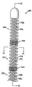
Figure 12 is an elevation view of one embodiment
of a heat transfer element according to the invention;
Figure 13 is a longitudinal section view of the
heat transfer element of Figure 1;
Figure 14 is a transverse section view of the
heat transfer element of Figure 1;
Figure 15 is a perspective view of the heat
transfer element of Figure 1 in use within a blood
vessel;
Figure 16 is a perspective view of another
embodiment of a heat transfer element according to the
invention, with aligned longitudinal ridges on
adjacent segments;
Figure 17 is a perspective view of another
embodiment of a heat transfer element according to the
invention, with somewhat offset longitudinal ridges on
adjacent segments; and
Page 30
CA 02454607 2007-07-19
Figure 18 is a transverse section view of the
heat transfer element of Figure 16 or Figure 17.
Figure 19 is a cut-away perspective view of an
alternative embodiment of a heat transfer element
according to the invention;
Figure 20 is a transverse section view of the
heat transfer element of Figure 5;
Figure 21 is a front sectional view of a further
embodiment of a catheter employing a heat transfer
element according to the principles of the invention
further employing a side-by-side lumen arrangement
constructed in accordance with an embodiment of the
invention;
Figure 22 is a cross-sectional view of the
catheter of Figure 21 taken along line 22-22 of
Figure 21;
Figure 23 is a front sectional view of a catheter
employing a heat transfer element and lumen
arranaement constructed in accordance with a further
embodiment of the invention;
Figure 24 is a front sectional view of a catheter
employing a heat transfer element and lumen
arrangement constructed in accordance with a still
further embodiment of the invention; and
Figure 25 is a front sectional view of a another
embodiment of a catheter employing a heat transfer
element according to the principles of the invention
further employing a side-by-side lumen arrangement
Page 31
CA 02454607 2007-07-19
constructed in accordance with another embodiment of
the invention; and
Figure 26 is a cross-sectional view of the heat
transfer element illustrated in Figure 25 taken along
line 26-26 of Figure 25.
Figure 27 is a side schematic view of an
inflatable turbulence-inducing heat transfer element
according to an embodiment of the invention, as the
same is disposed within an artery.
Figure 28 illustrates an inflatable turbulence-
inducing heat transfer element according to an
alternative embodiment of the invention employing a
surface area enhancing taper and a turbulence-inducing
shape.
Figure 29 illustrates a tapered joint which may
be employed in the embodiment of Figure 23.
Figure 30 illustrates a turbulence-inducing heat
transfer element according to a second alternative
embodiment of the invention emploving a surface area
enhancing taper and turbulence-inducing surface
features.
Figure 31 illustrates a type of turbulence-
inducing surface feature which may be employed in the
heat transfer element of the embodiment of Figure 28.
In Figure 31 a spiral feature is shown.
Figure 32 illustrates a heat transfer element
according to an alternative embodiment of the
invention employing a surface area enhancing taper.
Page 32
CA 02454607 2007-07-19
Figure 33 illustrates another type of turbulence-
inducing surface feature which may be employed in the
heat transfer element of the embodiment of Figure 27.
In Figure 33, a series of staggered protrusions are
shown.
Figure 34 is a transverse cross-sectional view of
the heat transfer element of the embodiment of Figure
33.
Figure 35 is a perspective view of the device of
the present invention in place in a common carotid
artery of a patient;
Figure 36 is a perspective view of the device
shown in Figure 35, with additional details of
construction;
Figure 37 is a transverse section view of the
device shown in Figure 36, along the section line 3-3;
and
Figure 38 is a partial longitudinal section view
of the device shown in Figure 30, showing the flow
path of the cooling fluid.
Figure 39 is a schematic representation of the
heat transfer element being used in one embodiment to
provide hypothermia to a patient by causing total body
cooling and then rewarming the body;
Figure 40 is a schematic representation of the
heat transfer element being used in one embodiment to
cool the brain of a patient and to warm the blood
returning from the brain in the jugular vein;
Page 33
CA 02454607 2007-07-19
Figure 41 is a schematic representation of the
heat transfer element being used in one embodiment to
cool the brain of a patient, while a warm saline
solution is infused to warm the blood returning from
the brain in the jugular vein; and
Figure 42 is a schematic representation of one
embodiment of an external warming device which can be
used to warm the blood returning from an organ in a
vein.
Figure 43 is a schematic representation of the
heat transfer element being used in another embodiment
to provide hypothermia to a patient by causing total
body cooling and then rewarming the body;
Figure 44 is a flowchart showing an exemplary
method of the invention employing heating blankets and
thermoregulatory drugs.
Figure 45 shows a meperidine molecule
Figure 46 shows a morphine molecule.
Figure 47 shows a prodine (+) isomer molecule.
Figure 48 shows a prodine (-) isomer molecule.
Figure 49 shows a fentanyl molecule.
Figure 50 shows a hydroxy allyl prodine (+)
isomer molecule.
Figure 51 shows a picenadol (+) isomermolecule.
Figure 52 shows a picenadol (-) isomer molecule.
Figure 53 shows a tramadol molecule.
Figure 54 shows a nefopam molecule.
Page 34
CA 02454607 2007-07-19
Figure 55 is a schematic representation of the
use of a heat transfer element to cool the body,
according to an embodiment of the invention.
Figure 56 is a flowchart showing an exemplary
method of the invention.
Figure 57 shows a catheter having a manifold
constructed in accordance with the present invention.
Figure 58 is an enlarged sectional view of a
fragmentary portion of the catheter shown in FIGURE
57.
Figure 59 is a perspective view of a heat
transfer catheter system including a circulation set
constructed in accordance with an embodiment of the
invention;
Figure 60 is a cross-sectional view of an
embodiment of a distal portion of a heat transfer
catheter along with a side-elevational view of an
embodiment of a proximal portion of the catheter that
may be used with the circulation set illustrated in
Figure 59;
Figure 61 is a schematic view of a valve that may
be employed in an embodiment of the present invention.
Figure 62 is a schematic diagram of the
circulation set illustrated in Figure 48;
Figure 63 is an exploded perspective view of an
embodiment of a disposable heat exchanger that may be
used in the circulation set of the present invention.
Page 35
CA 02454607 2007-07-19
Figure 64 is a cross sectional view of the heat
exchanger illustrated in Figure 52.
Figures 65 and 66 are perspective views of the
manifold portions of the heat exchanger illustrated in
Figure 63.
Figure 67 is a perspective view of a temperature
and pressure sensor assembly constructed in accordance
with an embodiment of the invention;
Figure 68 is an exploded perspective view of the
temperature and pressure sensor assembly illustrated
in Figure 67.
Figure 69 is an exploded side-elevational view of
the temperature and pressure sensor assembly
illustrated in Figure 67.
Figure 70 is an exploded perspective view of the
temperature and pressure sensor assembly illustrated
in Figure 67, but from a different vantage point from
that of Figure 68.
Figure 71 is an exemplary graph of a pump motor
speed versus time for a pump of the circulation set
illustrated in Figure 59.
Figure 72 is an exemplary graph of pressure
versus pump motor speed for a 10 F heat transfer
catheter and a 14 F heat transfer catheter used with
the circulation set illustrated in Figure 59.
Figure 73 is a schematic representation of layers
constituting a wall of the heat transfer element
Page 36
CA 02454607 2007-07-19
according to an embodiment of the invention and formed
by a method according to the invention;
Figure 74 is a schematic representation of layers
constituting a wall of the heat transfer element
according to a second embodiment of the invention and
formed by a method according to the invention;
Figure 75 is an exploded schematic representation
of layers constituting a wall of the heat transfer
element according to a third embodiment of the
invention and formed by a method according to the
invention;
Fig. 76 shows a system which may be used to
implement a predictive temperature algorithm.
Fig. 77 shows a junction between a heat transfer
element and a catheter showing position of a catheter-
mounted heat transfer element.
Fig. 78 shows a pump duty cycle.
Fig. 79 shows two pump duty cycles and the
achievement of a higher duty cycle, compared to that
of Fig. 78, when a predictive temperature algorithm is
employed.
Fig. 80 shows one graphical method of predicting
a control temperature.
Fig. 81 shows the relationship of the ratio of
areas, before measurement and after measurement, with
respect to time.
Fig. 82 shows another method of predicting a
control temperature.
Page 37
CA 02454607 2007-07-19
Fig. 83 shows a system which may implement a
method of predicting control temperatures.
Fig. 84 shows a graph of the areas of, e.g., Fig.
81.
Fig. 85 shows another system for implementing a
method of predicting control temperatures.
Fig. 86 shows a comparator switch which may be
used in the embodiment of, e.g., Fig. 85.
Page 38
CA 02454607 2007-07-19
DETAILED DESCRIPTION
OVERVIEW
In the following description, the term "pressure
communication" is used to describe a situation between
two points in a flow or in a standing fluici. If
pressure is applied at one point, the second point
will eventually feel effects of the pressure if the
two points are in pressure communication. Any number
of valves or elements may be disposed between the two
points, and the two points may still be in pressure
communication if the above test is met. For example,
for a standing fluid in a pipe, any number of pipe
fittings may be disposed between two pipes and, so
long as an open path is maintained, points in the
respective pipes may still be in pressure
communication.
A one or two-step process and a one or two-piece
device may be employed to intravascularly lower the
temperature of a body in order to induce therapeutic
hypothermia. A cooling element may be placed in a
high-flow vein such as the vena cavae to absorb heat
from the blood flowing into the heart. This transfer
of heat causes a cooling of the blood flowing through
the heart and thus throughout the vasculature. Such a
method and device may therapeutically be used to
induce an artificial state of hypothermia.
Page 39
CA 02454607 2007-07-19
A heat transfer element that systemically cools
blood should be capable of providing the necessary
heat transfer rate to produce the desired cooling
effect throughout the vasculature. This may be up to
or greater than 300 watts, and is at least partially
dependent on the mass of the patient and the rate of
blood flow. Surface features may be employed on the
heat transfer element to enhance the heat transfer
rate. The surface features and other components of
the heat transfer element are described in more detail
below.
One problem with hypothermia as a therapy is that
the patient's thermoregulatory defenses initiate,
attempting to defeat the hypothermia. Methods and
devices may be used to lessen the thermoregulatory
response. For example, a heating blanket may cover
the patient. In this way, the patient may be made
more comfortable. Thermoregulatory drugs may also be
employed to lower the trigger point at which the
patient's thermoregulatory system begins to initiate
defenses. Such drugs are described in more detail
below. A method employing thermoregulatory drugs,
heating blankets, and heat transfer elements is also
disclosed below.
2 5 ANATOMICAL PLACEMENT
The internal jugular vein is the vein that
directly drains the brain. The external jugular joins
Page 40
CA 02454607 2007-07-19
the internal jugular at the base of the neck. The
internal jugular veins join the subclavian veins to
form the brachiocephalic veins that in turn drain into
the superior vena cava. The superior vena cava drains
into the right atrium of the heart as may be seen by
referring ahead to Figure 1. The superior vena cava
supplies blood to the heart from the upper part of the
body.
A cooling element may be placed into the superior
vena cava, inferior vena cava, or otherwise into a
vein which feeds into the superior vena cava or
otherwise into the heart to cool the body. A
physician percutaneously places the catheter into the
subclavian or internal or external jugular veins to
access the superior vena cava. The blood, cooled by
the heat transfer element, may be processed by the
heart and provided to the body in oxygenated form to
be used as a conductive medium to cool the body. The
lungs have a fairly low heat capacity, and thus the
lungs do not cause appreciable rewarming of the
flowing blood.
The vasculature by its very nature provides
preferential blood flow to the high blood flow organs
such as the brain and the heart. Thus, these organs
are preferentially cooled by such a procedure as is
also shown experimentally in Figure 2. Figure 2 is a
graph of measured temperature plotted versus cooling
time. This graph show the effect of placing a cooling
Page 41
CA 02454607 2007-07-19
element in the superior vena cavae of a sheep. The
core body temperature as measured by an esophageal
probe is shown by curve 14. The brain temperature is
shown by curve 12. The brain temperature is seen to
decrease more rapidly than the core body temperature
throughout the experiment. The inventors believe thi:;
effect to be due to the preferential supply of blood
provided to the brain and heart. This effect may be
even more pronounced if thermoregulatory effects, such
as vasoconstriction, occur that tend to focus blood
supply to the core vascular system and away from the
peripheral vascular system.
HEAT TRANSFER
When a heat transfer element is inserted
approximately coaxially into an artery or vein, the
primary mechanism of heat transfer between the surface
of the heat transfer element and the blood is forced
convection. Convection relies upon the movement of
fluid to transfer heat. Forced convection results
when an external force causes motion within the fluid.
In the case of arterial or venous flow, the beating
heart causes the motion of the blood around the heat
transfer element.
The magnitude of the heat transfer rate is
proportional to the surface area of the heat transfer
element, the temperature differential, and the heat
transfer coefficient of the heat transfer element.
Page 42
CA 02454607 2007-07-19
The receiving artery or vein into which the heat
transfer element is placed has a limited diameter and
length. Thus, the surface area of the heat transfer
element must be limited to avoid significant
obstruction of the artery or vein and to allow the
heat :ransfer element to easily pass through the
vascular system. For placement within the superior
vena cava via the external jugular, the cross
sectional diameter of the heat transfer element may be
limited to about 5-6 mm, and its length may be limited
to approximately 10-15 cm. For placement within the
inferior vena cava, the cross sectional diameter of
the heat transfer element may be limited to about 6-7
mm, and its length may be limited to approximately 25-
35 cm.
Decreasing the surface temperature of the heat
transfer element can increase the temperature
differential. However, the minimum allowable surface
temperature is limited by the characteristics of
blood. Blood freezes at approximately 00 C. When the
blood approaches freezing, ice emboli may form in the
blood, which may lodge downstream, causing serious
ischemic injury. Furthermore, reducing the
temperature of the blood also increases its viscosity,
which results in a small decrease in the value of the
convection heat transfer coefficient. In addition,
increased viscosity of the blood may result in an
increase in the pressure drop within the artery, thus
Page 43
CA 02454607 2007-07-19
compromising the flow of blood to the brain. Given
the above constraints, it is advantageous to limit the
minimum allowable surface temperature of the cooling
element to approximately 5 C. This results in a
maximum temperature differential between the blood
stream and the cooling element of a.pproximately 32 C.
For other physiological reasons, there are limits on
the maximum allowable surface temperature of the
warming element.
The mechanisms by which the value of the
convection heat transfer coefficient may be increased
are complex. However, it is well known that the
convection heat transfer coefficient increases with
the level of "mixing" or "turbulent" kinetic energy in
the fluid flow. Thus it is advantageous to have blood
flow with a high degree of mixing in contact with the
heat transfer element.
The blood flow has a considerably more stable
flux in the superior vena cava than in an artery.
However, the blood flow in the superior vena cava
still has a high degree of inherent mixing or
turbulence. Reynolds numbers in the superior vena
cava may range, for example, from 2,000 to 5,000.
Thus, blood cooling in the superior vena cava may
benefit from enhancing the level of mixing with the
heat transfer element but this benefit may be
substantially less than that caused by the inherent
mixing.
Page 44
CA 02454607 2007-07-19
A thin boundary layer has been shown to form
during the cardiac cycle. Boundary layers develop
adjacent to the heat transfer element as well as next
to the walls of the artery or vein. Each of these
boundary layers has approximately the same thickness
as the boundary layer that would have developed at the
wall of the artery in the absence of the heat transfer
element. The free stream flow region is developed in
an annular ring around the heat transfer element. The
heat transfer element used in such a vessel should
reduce the formation of such viscous boundary layers.
HEAT TRANSFER ELEMENT CHARACTERISTICS
The intravascular heat transfer element should be
flexible in order to be placed within the vena cavae
or other veins or arteries. The flexibility of the
heat transfer element is an important characteristic
because the same is typically inserted into a vein
such as the external jugular and accesses the superior
vena cava by initially passing though a series of one
or more branches. Further, the heat transfer element
is ideally constructed from a highly thermally
conductive material such as metal in order to
facilitate heat transfer. The use of a highly
thermally conductive material increases the heat
transfer rate for a given temperature differential
between the working fluid within the heat transfer
element and the blood. This facilitates the use of a
Page 45
CA 02454607 2007-07-19
higher temperature coolant, or lower temperature
warming fluid, within the heat transfer element,
allowing safer working fluids, such as water or
saline, to be used. Highly thermally conductive
materials, such as metals, tend to be rigid.
Therefore, the di~sign of the heat transfer element
should facilitate flexibility in an inherently
inflexible material.
It is estimated that the cooling element should
absorb at least about 300 Watts of heat when placed in
the superior vena cava to lower the temperature of the
body to between about 30 C and 34 C. These
temperatures are thought to be appropriate to obtain
the benefits of hypothermia described above. The power
removed determines how quickly the target temperature
can be reached. For example, in a stroke therapy in
which it is desired to lower brain temperature, the
same may be lowered about 4 C per hour in a 70 kg human
upon removal of 300 Watts.
One embodiment of the invention uses a modular
design. This design creates helical blood flow and
produces a level of mixing in the blood flow by
periodically forcing abrupt changes in the direction
of the helical blood flow. The abrupt changes in flow
direction are achieved through the use of a series of
two or more heat transfer segments, each included of
one or more helical ridges. The use of periodic
abrupt changes in the helical direction of the blood
Page 46
CA 02454607 2007-07-19
flow in order to induce strong free stream turbulence
may be illustrated with reference to a common clothes
washing machine. The rotor of a washing machine spins
initially in one direction causing laminar flow. When
the rotor abruptly reverses direction, significant
turbulent kinetic energy is created within the entire
wash basin as the changing currents cause random
turbulent motion within the clothes-water slurry.
These surface features also tend to increase the
surface area of the heat transfer element, further
enhancing heat transfer.
A heat transfer element with a smooth exterior
surface may be able to provide the desired amount of
heat transfer. However, as noted above, it is well
known that the convection heat transfer coefficient
increases with the level of turbulent kinetic energy
in the fluid flow. Thus, if flow past a smooth heat
transfer element will not transfer sufficient heat, it
is advantageous to have turbulent or otherwise mixed
blood flow in contact with the heat transfer element.
Figure 3 is a graph illustrating steady state
turbulent flow. The vertical axis is the velocity of
the flow. The horizontal axis represents time. The
average velocity of the turbulent flow is shown by a
line 118. The actual instantaneous velocity of the
flow is shown by a curve 116.
Under constant pressure conditions, steady flows
in pipes are characterized as a balance between
Page 47
CA 02454607 2007-07-19
viscous stresses and the constant pressure gradient.
Such flows are called Poiseuillean. Figure 7 is a
velocity profile diagram showing a typical steady
state Poiseuillean flow driven by a constant pressure
gradient. The velocity of the fluid across the pipe
is shown in Figure 7 by the parabolic curve and
corresponding velocity vectors. The velocity of the
fluid in contact with the wall of the pipe is zero.
The boundary layer is the region of the flow in
contact with the pipe surface in which viscous
stresses are dominant. In steady state Poiseuillean
flow, the boundary layer develops until it includes
the whole pipe, i.e., the boundary layer thickness in
Figure 16 is one half of the diameter of the pipe.
Under conditions of Poiseuillean flow, the
Reynolds number, the ratio of inertial forces to
viscous forces, can be used to characterize the level
of turbulent kinetic energy existing in the flow. For
Poiseuillean flows, Reynolds numbers must be greater
than about 2300 to cause a transition from laminar to
turbulent flow. Further, when the Reynolds number is
greater than about 2000, the boundary layer is
receptive to "tripping". Tripping is a process by
which a small perturbation in the boundary layer can
create turbulent conditions. The receptivity of a
boundary layer to "tripping" is proportional to the
Reynolds number and is nearly zero for Reynolds
numbers less than 2000.
Page 48
CA 02454607 2007-07-19
In contrast with the steady Poiseuillean flow,
the blood flow in arteries is induced by the beating
heart and is therefore pulsatile. The below
description of this pulsatile flow, referring to
Figures 5-19, thus describes the situation when a heat
transfer element is inserted into an artery. Figure 4
is a graph showing the velocity of the blood flow
within an artery as a function of time. The beating
heart provides pulsatile flow with an approximate
period of 0.5 to 1 second. This is known as the
period of the cardiac cycle. The horizontal axis in
Figure 4 represents time in seconds and the vertical
axis represents the average velocity of blood in
centimeters per second. Although very high velocities
are reached at the peak of the pulse, the high
velocity occurs for only a small portion of the cycle.
In fact, the velocity of the blood reaches zero in the
carotid artery at the end of a pulse and temporarily
reverses.
Because of the relatively short duration of the
cardiac pulse, the blood flow in the arteries does not
develop into the classic Poiseuillean flow. Figure 8
is a velocity profile diagram showing blood flow
velocity within an artery averaged over the cardiac
pulse. The majority of the flow within the artery has
the same velocity. The boundary layer where the flow
velocity decays from the free stream value to zero is
very thin, typically 1/6 to 1/20 of the diameter of
Page 49
CA 02454607 2007-07-19
the artery, as opposed to one half of the diameter of
the artery in the Poiseuillean flow condition.
As noted above, if the flow in the artery were
steady rather than pulsatile, the transition from
laminar to turbulent flow would occur when the value
of the Reynolds number exceeds about 2,000. However,
in the pulsatile arterial flow, the value of the
Reynolds number varies during the cardiac cycle, just
as the flow velocity varies. In pulsatile flows, due
to the enhanced stability associated with the
acceleration of the free stream flow, the critical
value of the Reynolds number at which the unstable
modes of motion grow into turbulence is found to be
much higher, perhaps as high as 9,000.
The blood flow in the arteries of interest
remains laminar over more than 80% of the cardiac
cycle. Referring again to Figure 4, the blood flow is
turbulent from approximately time tl until time t2
during a small portion of the descending systolic
flow, which is less than 20% of the period of the
cardiac cycle. If a heat transfer element is placed
inside the artery, heat transfer will be facilitated
during this short interval. However, to transfer the
necessary heat to selectively cool the brain, in
arterial embodiments, turbulent kinetic energy should
be produced in the blood stream and sustained
throughout the entire period of the cardiac cycle.
Page 50
CA 02454607 2007-07-19
A thin boundary layer has been shown to form
during the cardiac cycle. This boundary layer will
form over the surface of a smooth heat transfer
element. Figure 9 is a velocity profile diagram
showing blood flow velocity within an artery, averaged
over the cardiac pulse, after insertion of a smooth
heat transfer element within the artery. In Figure 9,
the diameter of the heat transfer element is about one
half of the diameter of the artery. Boundary layers
develop adjacent to the heat transfer element as well
as next to the walls of the artery. Each of these
boundary layers has approximately the same thickness
as the boundary layer which would have developed at
the wall of the artery in the absence of the heat
transfer element. The free stream flow region is
developed in an annular ring around the heat transfer
element. Blood flow past such a smooth heat transfer
element may transfer sufficient heat to accomplish the
desired temperature control.
One way to increase the heat transfer rate is to
create a turbulent boundary layer on the heat transfer
element surface. However, turbulence in the very thin
boundary layer will not produce sufficient kinetic
energy to produce the necessary heat transfer rate.
Therefore, to induce sufficient turbulent kinetic
energy to increase the heat transfer rate sufficiently
to cool the brain, a stirring mechanism, which
abruptly changes the direction of velocity vectors,
Page 51
CA 02454607 2007-07-19
should be utilized. This can create high levels of
turbulence intensity in the free stream, thereby
sufficiently increasing the heat transfer rate.
This turbulence intensity should ideally be
sustained for a significant portion of the cardiac
cycle. Further, turbulent kinetic energy should
ideally be created throughout the free stream and not
just in the boundary layer. Figure 5 is a graph
illustrating the velocity of continually turbulent
flow under pulsatile conditions as a function of time,
which would result in optimal heat transfer in
arterial blood flow. Turbulent velocity fluctuations
are seen throughout the cycle as opposed to the short
interval of fluctuations seen in Figure 4 between time
tl and time t2. These velocity fluctuations are found
within the free stream. The turbulence intensity
shown in Figure 5 is at least 0.05. In other words,
the instantaneous velocity fluctuations deviate from
the mean velocity by at least 5%. Although, ideally,
turbulence or mixing is created throughout the entire
period of the cardiac cycle, the benefits of
turbulence are also obtained if the turbulence or
mixing is sustained for only 75%, 50% or even as low
as 30% or 20% of the cardiac cycle.
To create the desired level of turbulence
intensity or mixing in the blood free stream during
the whole cardiac cycle, one embodiment of the
invention uses a modular design. This design creates
Page 52
CA 02454607 2007-07-19
helical blood flow and produces a high level of mixing
in the free stream.
For a swirling flow in a tube in which the
azimuthal velocity of the fluid vanishes toward the
stationary outer boundary, any non-vanishing azimuthal
velocity in the interior of the flow will result in an
instability in which the inner fluid is spontaneously
exchanged with fluid near the wall, analogous to
Taylor cells in the purely azimuthal flow between a
rotating inner cylinder and stationary outer cylinder.
This instability results from the lack of any force in
opposition to the centripetal acceleration of the
fluid particles moving along helical paths, the
pressure in the tube being a function only of
longitudinal position. In one embodiment, the device
of the present invention imparts an azimuthal velocity
to the interior of a developed pipe flow, with the net
result being a continuous exchange of fluid between
the core and perimeter of the flow as it moves
longitudinally down the pipe. This fluid exchange
enhances the transport of heat, effectively increasing
the convective heat transfer coefficient over that
which would have obtained in undisturbed pipe flow.
This bulk exchange of fluid is not necessarily
turbulent, although turbulence is possible if the
induced azimuthal velocity is sufficiently high.
Figure 6 is a perspective view of such a
turbulence inducing or mixing-inducing heat transfer
Page 53
CA 02454607 2007-07-19
element within an artery. In this embodiment,
turbulence or mixing is further enhanced by
periodically forcing abrupt changes in the direction
of the helical blood flow. Turbulent or mixed flow
would be found at point 120, in the free stream area.
The abrupt changes in flow direction are achieved
through the use of a series of two or more heat
transfer segments, each comprised of one or more
helical ridges. Ideally, the segments will be close
enough together to prevent re-laminarization of the
flow in between segments.
The use of periodic abrupt changes in the helical
direction of the blood flow in order to induce strong
free stream turbulence or mixing may be illustrated
with reference to a common clothes washing machine.
The rotor of a washing machine spins initially in one
direction causing laminar flow. When the rotor
abruptly reverses direction, significant turbulent
kinetic energy is created within the entire wash basin
as the changing currents cause random turbulent mixing
motion within the clothes-water slurry.
A device according to an embodiment of the
invention for accomplishing such cooling or heating is
shown schematically in Figure 10, which shows a vessel
wall 132 in which a blood flow 100 is passing. A
catheter 130 is disposed within the blood flow 100 to
affect the blood temperature. Catheter 101 has an
inlet lumen 126 for providing a working fluid 107 and
Page 54
CA 02454607 2007-07-19
an outlet lumen 124 for draining the working fluid
128. The functions of the respective lumens may of
course be opposite to that stated. A reverse
configuration may be particularly advantageous when
blood heating, rather than blood cooling, is the
objective.
Heat transfer in this system is governed by the
following mechanisms:
(1) convective heat transfer from the blood 122 to
the outlet lumen 124;
(2) conduction through the wall of the outlet lumen
124;
(3) convective heat transfer from the outlet
lumen 124 to the working fluid 128;
(4) conduction through the working fluid 128;
(5) convective heat transfer from working fluid 128
in the outlet lumen 124 to the inlet lumen 126;
and
(6) conduction through the wall of the inlet lumen
126.
Once the materials for the lumens and the working
fluid are chosen, the conductive heat transfers are
solely dependent on the temperature gradients.
Convective heat transfers, by contrast, also rely on
the movement of fluid to transfer heat. Forced
convection results when the heat transfer surface is
in contact with a fluid whose motion is induced (or
forced) by a pressure gradient, area variation, or
Page 55
CA 02454607 2007-07-19
other such force. In the case of arterial flow, the
beating heart provides an oscillatory pressure
gradient to force the motion of the blood in contact
with the heat transfer surface. One of the aspects of
the device uses turbulence to enhance this forced
convective heat transfer.
The rate of convective heat transfer Q is
proportional to the product of S. the area of the heat
transfer element in direct contact with the fluid,
OT = Tb- T5, the temperature differential between the
surface temperature T. of the heat transfer element and
the free stream blood temperature Tb, and h,, the
average convection heat transfer coefficient over the
heat transfer area. h,is sometimes called the "surface
coefficient of heat transfer" or the "convection heat
transfer coefficient".
The magnitude of the heat transfer rate Q to or
from the fluid flow can be increased through
manipulation of the above three parameters_ Practical
constraints limit the value of these parameaters and
how much they can be manipulated. For example, the
internal diameter of the common carotid artery ranges
from 6 to 8 mm. Thus, the heat transfer element
residing therein may not be much larger than 4 mm in
diameter to avoid occluding the vessel. The length of
the heat transfer element should also be limited. For
placement within the internal and common carotid
artery, the length of the heat transfer element is
Page 56
CA 02454607 2007-07-19
limited to about 10 cm. This estimate is based on the
length of the common carotid artery, which ranges from
8 to 12 cm. Embodiments intended for use in the venous
system would be analyzed similarly.
Consequently, the value of the surface area S is
limited by the physical constraints imposed by the
size of the artery into which the device is placed.
Surface features, such as fins, can be used to
increase the surface area of the heat transfer
element, however, these features alone cannot usually
provide enough surface area enhancement to meet the
required heat transfer rate. An embodiment of the
device described below provides a tapered heat
transfer element which employs a large surface area
but which may advantageously fit into small arteries
and veins. As the device is inflatable, the same may
be inserted in relatively small arteries and veins in
a deflated state, allowing a minimally invasive entry.
When the device is in position, the same may be
inflated, allowing a large surface area and thus an
enhanced heat transfer rate.
One may also attempt to vary the magnitude of the
heat transfer rate by varying AT. The value of
OT = Tb- TS can be varied by varying the surface
temperature T. of the heat transfer element. The
allowable surface temperature of the heat transfer
element is limited by the characteristics of blood.
The blood temperature is fixed at about 37 C, and blood
Page 57
CA 02454607 2007-07-19
freezes at approximately 0 C. When the blood
approaches freezing, ice emboli may form in the blood
which may lodge downstream, causing serious ischemic
injury. Furthermore, reducing the temperature of the
blood also increases its viscosity which results in a
small decrease in the value of h,. Increased viscosity
of the blood may further result in an increase in the
pressure drop within the vessel, thus compromising the
flow of blood. Given the above constraints, it is
advantageous to limit the surface temperature of the
heat transfer element to approximately 1 C - 5 C, thus
resulting in a maximum temperature differential
between the blood stream and the heat transfer element
of approximately 32 C - 36 C.
One may also attempt to vary the magnitude of the
heat transfer rate by varying h . Fewer constraints
are imposed on the value of the convection heat
transfer coefficient h.. The mechanisms by which the
value of h. may be increased are complex. However, one
way to increase h,, for a -ifixed mean value of the
velocity is to increase the level of turbulent kinetic
energy in the fluid flow.
The heat transfer rate Qno_tloW in the absence of
fluid flow is proportional to AT, the temperature
differential between the surface temperature TS of the
heat transfer element and the free stream blood
temperature Tb times k, the diffusion constant, and is
Page 58
CA 02454607 2007-07-19
inversely proportion to S, the thickness of the
boundary layer.
The magnitude of the enhancement in heat transfer
by fluid flow can be estimated by taking the ratio of
the heat transfer rate with fluid flow to the heat
transfer ra---e in the absence of fluid flow N = QfloW /
Qno-flow = hc /(k/8) . This ratio is called the Nusselt
number ("Nu"). For convective heat transfer between
blood and the surface of the heat transfer element,
Nusselt numbers of 30-80 have been found to be
appropriate for selective cooling applications of
various organs in the human body. Nusselt numbers are
generally dependent on several other numbers: the
Reynolds number, the Womersley number, and the Prandtl
number.
Stirring-type mechanisms, which abruptly change
the direction of velocity vectors, may be utilized to
induce turbulent kinetic energy and increase the heat
transfer rate. The level of turbulence so created is
characterized by the turbulence intensity $.
Turbulence intensity 3 is defined as the root mean
square of the fluctuating velocity divided by the mean
velocity. Such mechanisms can create high levels of
turbulence intensity in the free stream, thereby
increasing the heat transfer rate. This turbulence
intensity should ideally be sustained for a
significant portion of the cardiac cycle, and should
Page 59
CA 02454607 2007-07-19
ideally be created throughout the free stream and not
just in the boundary layer.
Turbulence does occur for a short period in the
cardiac cycle anyway. In particular, the blood flow
is turbulent during a small portion of the descending
systolic flow. This portion is less thar, 20% of the
period of the cardiac cycle. If a heat transfer
element is placed co-axially inside the artery, the
heat transfer rate will be enhanced during this short
interval. For typical of these fluctuations, the
turbulence intensity is at least 0.05. In other
words, the instantaneous velocity fluctuations deviate
from the mean velocity by at least 5%. Although
ideally turbulence is created throughout the entire
period of the cardiac cycle, the benefits of
turbulence are obtained if the turbulence is sustained
for 75%, 50% or even as low as 30% or 20% of the
cardiac cycle_
One type of turbulence-inducing heat transfer
element which may be advantageously employed to
provide heating or cooling of an organ or volume is
described in U.S. Patent No. 6,096,068 to Dobak and
Lasheras for a "Selective Organ Cooling Catheter and
Method of Using the Same". In that application, the
heat transfer element is made of a high thermal
conductivity material, such as metal. The metal heat
transfer element provides a high degree of heat
transfer due to its high thermal conductivity. In
Page 60
CA 02454607 2007-07-19
that application, bellows provided a high degree of
articulation that compensated for the intrinsic
stiffness of the metal. The device size was
minimized, e.g., less than 4 mm, to prevent blockage
of the blood flowing in the artery.
Figure 11 illustrates the dependency of the
Nusselt number on the Reynolds number for a fluid
flowing through a long duct, i.e., air flowing though
a long heated pipe at a uniform wall temperature.
Although Figure 11 illustrates this relationship for a
different fluid through a different structure, the
inventors of the present invention believe a similar
relationship exists for blood flow through a blood
vessel. Figure 11 illustrates that flow is laminar
when the Reynolds number is below some number, in this
case about 2100. In the range of Reynolds numbers
between another set of numbers, in this case 2100 and
10,000, a transition from laminar to turbulent flow
takes place. The flow in this regime is called
transitional. The mixing caused by the heat transfer
element of the present invention produces a flow that
is at least transitional. At another Reynolds number,
in the case above, about 10,000, the flow becomes
fully turbulent.
The type of flow that occurs is important because
in laminar flow through a duct, there is no mixing of
warmer and colder fluid particles by eddy motion.
Thus, the only heat transfer that takes place is
Page 61
CA 02454607 2007-07-19
through conduction. Since most fluids have small
thermal conductivities, the heat transfer coefficients
in laminar flow are relatively small. In transitional
and turbulent flow, mixing occurs through eddies that
carry warmer fluid into cooler regions and vice versa.
Since the mixing motion, even if it is only on a small
scale compared to fully turbulent flow, accelerates
the transfer of heat considerably, a marked increase
in the heat transfer coefficient occurs above a
certain Reynolds number, which in the graph of
Figure 11 is about 2100. It can be seen from
Figure 11 that it is at approximately this point where
the Nusselt number increases more dramatically. A
different set of numbers may be measured for blood
flow through an artery or vein. However, the
inventors believe that a Nusselt number at least in
the transitional region is important for enhanced heat
transfer.
DEVICE
Figure 12 is an elevation view of one embodiment
of a cooling element 102 according to the present
invention. The heat transfer element 102 includes a
series of elongated, articulated segments or modules
134,104,106. Three such segments are shown in this
embodiment, but two or more such segments could be
used without departing from the spirit of the
invention. As seen in Figure 12, a first elongated
Page 62
CA 02454607 2007-07-19
heat transfer segment 134 is located at the proximal
end of the heat transfer element 102. A mixing-
inducing exterior surface of the segment 134 includes
four parallel helical ridges 138 with four parallel
helical grooves 136 therebetween. One, two, three, or
more parallel helical ridges 138 could also be used
without departing from the spirit of the present
invention. In this embodiment, the helical ridges 138
and the helical grooves 136 of the heat transfer
segment 134 have a left hand twist, referred to herein
as a counter-clockwise spiral or helical rotation, as
they proceed toward the distal end of the heat
transfer segment 134.
The first heat transfer segment 134 is coupled to
a second elongated heat transfer segment 104 by a
first bellows section 140, which provides flexibility
and compressibility. The second heat transfer segment
104 includes one or more helical ridges 144 with one
or more helical grooves 142 therebetween. The ridges
144 and grooves 142 have a right hand, or clockwise,
twist as they proceed toward the distal end of the
heat transfer segment 104. The second heat transfer
segment 104 is coupled to a third elongated heat
transfer segment 106 by a second bellows section 108.
The third heat transfer segment 106 includes one or
more helical ridges 148 with one or more helical
grooves 146 therebetween. The helical ridge 148 and
the helical groove 146 have a left hand, or counter-
Page 63
CA 02454607 2007-07-19
clockwise, twist as they proceed toward the distal end
of the heat transfer segment 106. Thus, successive
heat transfer segments 134, 104, 106 of the heat
transfer element 102 alternate between having
clockwise and counterclockwise helical twists. The
actt:al left or right hand twist of any particular
segment is immaterial, as long as adjacent segments
have opposite helical twist.
In addition, the rounded contours of the ridges
138, 144, 148 allow the heat transfer element 102 to
maintain a relatively atraumatic profile, thereby
minimizing the possibility of damage to the blood
vessel wall. A heat transfer element according to the
present invention may include two, three, or more heat
transfer segments.
The bellows sections 140, 108 are formed from
seamless and nonporous materials, such as metal, and
therefore are impermeable to gas, which can be
particularly important, depending on the type of
working fluid that is cycled through the heat transfer
element 102. The structure of the bellows sections
140, 108 allows them to bend, extend and compress,
which increases the flexibility of the heat transfer
element 102 so that it is more readily able to
navigate through blood vessels. The bellows sections
140, 108 also provide for axial compression of the
heat transfer element 102, which can limit the trauma
when the distal end of the heat transfer element 102
Page 64
CA 02454607 2007-07-19
abuts a blood vessel wall. The bellows sections 140,
108 are also able to tolerate cryogenic temperatures
without a loss of performance. In alternative
embodiments, the bellows may be replaced by flexible
polymer tubes, which are bonded between adjacent heat
transfer segments.
The exterior surfaces of the heat transfer
element 102 can be made from metal, and may include
very high thermal conductivity materials such as
nickel, thereby facilitating heat transfer.
Alternatively, other metals such as stainless steel,
titanium, aluminum, silver, copper and the like, can
be used, with or without an appropriate coating or
treatment to enhance biocompatibility or inhibit clot
formation. Suitable biocompatible coatings include,
e.g., gold, platinum or polymer paralyene. The heat
transfer element 102 may be manufactured by plating a
thin layer of metal on a mandrel that has the
appropriate pattern. In this way, the heat transfer
element 102 may be manufactured inexpensively in large
quantities, which is an important feature in a
disposable medical device.
Because the heat transfer element 102 may dwell
within the blood vessel for extended periods of time,
such as 24-48 hours or even longer, it may be
desirable to treat the surfaces of the heat transfer
element 102 to avoid clot formation. In particular,
one may wish to treat the bellows sections 140, 108
Page 65
CA 02454607 2007-07-19
because stagnation of the blood flow may occur in the
convolutions, thus allowing clots to form and cling to
the surface to form a thrombus. One means by which to
prevent thrombus formation is to bind an
antithrombogenic agent to the surface of the heat
transfer element 102. For example, heparin is known
to inhibit clot formation and is also known to be
useful as a biocoating. Alternatively, the surfaces
of the heat transfer element 102 may be bombarded with
ions such as nitrogen. Bombardment with nitrogen can
harden and smooth the surface and thus prevent
adherence of clotting factors. Another coating that
provides beneficial properties may be a lubricious
coating. Lubricious coatings, on both the heat
transfer element and its associated catheter, allow
for easier placement in the, e.g., vena cava.
Figure 13 is a longitudinal sectional view of the
heat transfer element 102 of an embodiment of the
invention, taken along line 2-2 in Figure 12. Some
interior contours are omitted for purposes of clarity.
An inner tube 150 creates an inner lumen 158 and an
outer lumen 156 within the heat transfer element 102.
Once the heat transfer element 102 is in place in the
blood vessel, a working fluid such as saline or other
aqueous solution may be circulated through the heat
transfer element 102. Fluid flows up a supply
catheter into the inner lumen 158. At the distal end
of the heat transfer element 102, the working fluid
Page 66
CA 02454607 2007-07-19
exits the inner lumen 158 and enters the outer lumen
156. As the working fluid flows through the outer
lumen 156, heat is transferred from the working fluid
to the exterior surface 152 of the heat transfer
element 102. Because the heat transfer element 102 is
constructed from a high conductivity material, the
temperature of its exterior surface 152 may reach very
close to the temperature of the working fluid. The
tube 150 may be formed as an insulating divider to
thermally separate the inner lumen 158 from the outer
lumen 156. For example, insulation may be achieved by
creating longitudinal air channels in the wall of the
insulating tube 150. Alternatively, the insulating
tube 150 may be constructed of a non-thermally
conductive material like polytetrafluoroethylene or
another polymer.
It is important to note that the same mechanisms
that govern the heat transfer rate between the
exterior surface 152 of the heat transfer element 102
and the blood also govern the heat transfer rate
between the working fluid and the interior surface 154
of the heat transfer element 102. The heat transfer
characteristics of the interior surface 154 are
particularly important when using water, saline or
other fluid that remains a liquid as the working
fluid. Other coolants such as FREON undergo nucleate
boiling and create mixing through a different
mechanism. Saline is a safe working fluid, because it
Page 67
CA 02454607 2007-07-19
is non-toxic, and leakage of saline does not result in
a gas embolism, which could occur with the use of
boiling refrigerants. Since mixing in the working
fluid is enhanced by the shape of the interior surface
154 of the heat transfer element 102, the working
fluid can be delivered to the cooling element 102 at a
warmer temperature and still achieve the necessary
cooling rate. Similarly, since mixing in the working
fluid is enhanced by the shape of the interior surface
of the heat transfer element, the working fluid can be
delivered to the warming element 102 at a cooler
temperature and still achieve the necessary warming
rate.
This has a number of beneficial implications in
the need for insulation along the catheter shaft
length. Due to the decreased need for insulation, the
catheter shaft diameter can be made smaller. The
enhanced heat transfer characteristics of the interior
surface of the heat transfer element 102 also allow
the working fluid to be delivered to the heat transfer
element 102 at lower flow rates and lower pressures.
High pressures may make the heat transfer element
stiff and cause it to push against the wall of the
blood vessel, thereby shielding part of the exterior
surface 152 of the heat transfer element 102 from the
blood. Because of the increased heat transfer
characteristics achieved by the alternating helical
ridges 138, 144, 148, the pressure of the working
Page 68
CA 02454607 2007-07-19
fluid may be as low as 5 atmospheres, 3 atmospheres, 2
atmospheres or even less than 1 atmosphere.
Figure 14 is a transverse sectional view of the
heat transfer element 102 of the invention, taken at a
location denoted by the line 3-3 in Figure 12.
Figure 14 illustrates a five-lobed embodiment, whereas
Figure 12 illustrates a four-lobed embodiment. As
mentioned earlier, any number of lobes might be used.
In Figure 14, the construction of the heat transfer
element 102 is clearly shown. The inner lumen 158 is
defined by the insulating tube 150. The outer lumen
156 is defined by the exterior surface of the
insulating tube 150 and the interior surface 154 of
the heat transfer element 102. In addition, the
helical ridges 144 and helical grooves 142 may be seen
in Figure 14. Although Figure 14 shows four ridges
and four grooves, the number of ridges and grooves may
vary. Thus, heat transfer elements with 1, 2, 3, 4,
5, 6, 7, 8 or more ridges are specifically
contemplated.
Figure 15 is a perspective view of a heat
transfer element 102 in use within a blood vessel,
showing only one helical lobe per segment for purposes
of clarity. Beginning from the proximal end of the
heat transfer element (not shown in Figure 15), as the
blood moves forward, the first helical heat transfer
segment 134 induces a counter-clockwise rotational
inertia to the blood. As the blood reaches the second
Page 69
CA 02454607 2007-07-19
segment 104, the rotational direction of the inertia
is reversed, causing mixing within the blood.
Further, as the blood reaches the third segment 106,
the rotational direction of the inertia is again
reversed. The sudden changes in flow direction
actively reorient and raniomize the velocity vectors,
thus ensuring mixing throughout the bloodstream.
During such mixing, the velocity vectors of the blood
become more random and, in some cases, become
perpendicular to the axis of the vessel. Thus, a
large portion of the volume of warm blood in the
vessel is actively brought in contact with the heat
transfer element 102 where it can be cooled by direct
contact rather than being cooled largely by conduction
through adjacent laminar layers of blood.
Referring back to Figure 12, the heat transfer
element 102 has been designed to address all of the
design criteria discussed above. First, the heat
transfer element 102 is flexible and is made of a
highly conductive material. The flexibility is
provided by a segmental distribution of bellows
sections 140, 108 that provide an articulating
mechanism. Bellows have a known convoluted design
that provide flexibility. Second, the exterior
surface area 152 has been increased through the use of
helical ridges 138, 144, 148 and helical grooves 136,
142, 146. The ridges also allow the heat transfer
element 102 to maintain a relatively atraumatic
Page 70
CA 02454607 2007-07-19
profile, thereby minimizing the possibility of damage
to the vessel wall. Third, the heat transfer element
102 has been designed to promote mixing both
internally and externally. The modular or segmental
design allows the direction of the grooves to be
reversed between segments. The alternating helical
rotations create an alternating flow that results in
mixing the blood in a manner analogous to the mixing
action created by the rotor of a washing machine that
switches directions back and forth. This action is
intended to promote mixing to enhance the heat
transfer rate. The alternating helical design also
causes beneficial mixing, or turbulent kinetic energy,
of the working fluid flowing internally.
Figure 16 is a perspective view of a third
embodiment of a heat transfer element 160 according to
the present invention. The heat transfer element 160
is comprised of a series of elongated, articulated
segments or modules 162_ A first elongated heat
transfer segment 162 is located at the proximal end of
the heat transfer element 160. The segment 162 may be
a smooth right circular cylinder, as addressed in
Figure 9, or it can incorporate a turbulence-inducing
or mixing-inducing exterior surface. The turbulence-
inducing or mixing-inducing exterior surface shown on
the segment 162 in Figure 16 comprises a plurality of
parallel longitudinal ridges 164 with parallel
longitudinal grooves 168 therebetween. One, two,
Page 71
CA 02454607 2007-07-19
three, or more parallel longitudinal ridges 164 could
be used without departing from the spirit of the
present invention. In the embodiment where they are
used, the longitudinal ridges 164 and the longitudinal
grooves 168 of the heat transfer segment 162 are
alignec; parallel with the axis of the first heat
transfer segment 162.
The first heat transfer segment 162 is coupled to
a second elongated heat transfer segment 162 by a
first flexible section such as a bellows section 166,
which provides flexibility and compressibility.
Alternatively, the flexible section may be a simple
flexible tube, very similar to a smooth heat transfer
segment as addressed in Figure 9, but flexible. The
second heat transfer segment 162 also comprises a
plurality of parallel longitudinal ridges 164 with
parallel longitudinal grooves 168 therebetween. The
longitudinal ridges 164 and the longitudinal grooves
168 of the second heat transfer segment 162 are
aligned parallel with the axis of the second heat
transfer segment 162. The second heat transfer
segment 162 is coupled to a third elongated heat
transfer segment 162 by a second flexible section such
as a bellows section 166 or a flexible tube. The
third heat transfer segment 162 also comprises a
plurality of parallel longitudinal ridges 164 with
parallel longitudinal grooves 168 therebetween. The
longitudinal ridges 164 and the longitudinal grooves
Page 72
CA 02454607 2007-07-19
168 of the third heat transfer segment 162 are aligned
parallel with the axis of the third heat transfer
segment 162. Further, in this embodiment, adjacent
heat transfer segments 162 of the heat transfer
element 160 have their longitudinal ridges 164 aligned
with each other, and their longitudinal grooves 168
aligned with each other.
In addition, the rounded contours of the ridges
164 also allow the heat transfer element 160 to
maintain a relatively atraumatic profile, thereby
minimizing the possibility of damage to the blood
vessel wall. A heat transfer element 160 according to
the present invention may be comprised of two, three,
or more heat transfer segments 162.
The bellows sections 166 are formed from seamless
and nonporous materials, such as metal, and therefore
are impermeable to gas, which can be particularly
important, depending on the type of working fluid
which is cycled through the heat transfer element 160.
The structure of the bellows sections 166 allows them
to bend, extend and compress, which increases the
flexibility of the heat transfer element 160 so that
it is more readily able to navigate through blood
vessels. The bellows sections 166 also provide for
axial compression of the heat transfer element 160,
which can limit the trauma when the distal end of the
heat transfer element 160 abuts a blood vessel wall.
Page 73
CA 02454607 2007-07-19
The bellows sections 166 are also able to tolerate
cryogenic temperatures without a loss of performance.
Figure 17 is a perspective view of a fourth
embodiment of a heat transfer element 170 according to
the present invention. The heat transfer element 170
is comprised of a series of elongated, articulated
segments or modules 172. A first elongated heat
transfer segment 172 is located at the proximal end of
the heat transfer element 170. A turbulence-inducing
or mixing-inducing exterior surface of the segment 172
comprises a plurality of parallel longitudinal ridges
174 with parallel longitudinal grooves 176
therebetween. One, two, three, or more parallel
longitudinal ridges 174 could be used without
departing from the spirit of the present invention.
In this embodiment, the longitudinal ridges 174 and
the longitudinal grooves 176 of the heat transfer
segment 172 are aligned parallel with the axis of the
first heat transfer segment 172.
The first heat transfer segment 172 is coupled to
a second elongated heat transfer segment 172 by a
first flexible section such as a bellows section 178,
which provides flexibility and compressibility.
Alternatively, the flexible section may be a simple
flexible tube, very similar to a smooth heat transfer
segment as shown in Figure 9, but flexible. The
second heat transfer segment 172 also comprises a
plurality of parallel longitudinal ridges 174 with
Page 74
CA 02454607 2007-07-19
parallel longitudinal grooves 176 therebetween. The
longitudinal ridges 174 and the longitudinal grooves
176 of the second heat transfer segment 172 are
aligned parallel with the axis of the second heat
transfer segment 172. The second heat transfer
segment 172 is coupled to a third elongated heat
transfer segment 172 by a second flexible section such
as a bellows section 178 or a flexible tube. The
third heat transfer segment 172 also comprises a
plurality of parallel longitudinal ridges 174 with
parallel longitudinal grooves 176 therebetween. The
longitudinal ridges 174 and the longitudinal grooves
176 of the third heat transfer segment 172 are aligned
parallel with the axis of the third heat transfer
segment 172. Further, in this embodiment, adjacent
heat transfer segments 172 of the heat transfer
element 170 have their longitudinal ridges 174
angularly offset from each other, and their
longitudinal grooves 176 angularly offset from each
other. Offsetting of the longitudinal ridges 174 and
the longitudinal grooves 176 from each other on
adjacent segments 172 promotes turbulence or mixing in
blood flowing past the exterior of the heat transfer
element 170.
Figure 18 is a transverse section view of a heat
transfer segment 180, illustrative of segments 162,
172 of heat transfer elements 160, 170 shown in Figure
16 and Figure 17. The coaxial construction of the
Page 75
CA 02454607 2007-07-19
heat transfer segment 180 is clearly shown. The inner
coaxial lumen 182 is defined by the insulating coaxial
tube 184. The outer lumen 190 is defined by the
exterior surface of the insulating coaxial tube 184
and the interior surface 192 of the heat transfer
segment 180. In addition, parallel longitudinal
ridges 186 and parallel longitudinal grooves 188 may
be seen in Figure 18. The longitudinal ridges 186 and
the longitudinal grooves 188 may have a relatively
rectangular cross-section, as shown in Figure 18, or
they may be more triangular in cross-section, as shown
in Figures 16 and 17. The longitudinal ridges 186 and
the longitudinal grooves 188 may be formed only on the
exterior surface of the segment 180, with a
cylindrical interior surface 192. Alternatively,
corresponding longitudinal ridges and grooves may be
formed on the interior surface 192 as shown, to
promote turbulence or mixing in the working fluid.
Although Figure 18 shows six ridges and six grooves,
the number of ridges and grooves may vary. Where a
smooth exterior surface is desired, the outer tube of
the heat transfer segment 180 could have smooth outer
and inner surfaces, like the inner tube 184.
Alternatively, the outer tube of the heat transfer
segment 180 could have a smooth outer surface and a
ridged inner surface like the interior surface 192
shown in Figure 18.
Page 76
CA 02454607 2007-07-19
Figure 19 is a cut-away perspective view of an
alternative embodiment of a heat transfer element 194.
An external surface 196 of the heat transfer element
194 is covered with a series of axially staggered
protrusions 198. The staggered nature of the outer
protrusions 198 is readily seen with reference to
Figure 20 which is a transverse cross-sectional view
taken at a location denoted by the line 6-6 in Figure
19. As the blood flows along the external surface
196, it collides with one of the staggered protrusions
198 and a turbulent wake flow is created behind the
protrusion. As the blood divides and swirls alongside
of the first staggered protrusion 198, its turbulent
wake encounters another staggered protrusion 198
within its path preventing the re-lamination of the
flow and creating yet more mixing. In this way, the
velocity vectors are randomized and mixing is created
not only in the boundary layer but also throughout a
large portion of the free stream. As is the case with
the preferred embodiment, this geometry also induces a
mixing effect on the internal working fluid flow.
A working fluid is circulated up through an
inner lumen 200 defined by an insulating tube 202 to a
distal tip of the heat transfer element 194. The
working fluid then traverses an outer lumen 204 in
order to transfer heat to the exterior surface 196 of
the heat transfer element 194. The inside surface of
the heat transfer element 194 is similar to the
Page 77
CA 02454607 2007-07-19
exterior surface 196 in order to induce turbulent flow
of the working fluid. The inner protrusions can be
aligned with the outer protrusions 198 as shown in
Figure 20 or they can be offset from the outer
protrusions 198 as shown in Figure 19.
With reference to Figures 21 and 22, a catheter
206 constructed in accordance with an alternative
embodiment of the invention will now be described.
The catheter 206 includes an elongated catheter body
208 with a heat transfer element 210 located at a
distal portion 212 of the catheter body 208. The
catheter 206 includes a multiple lumen arrangement 214
to deliver fluid to and from an interior 216 of the
heat transfer element 210 and allow the catheter 206
to be placed into a blood vessel over a guidewire.
The heat transfer element 210 includes turbulence-
inducing invaginations 218 located on an exterior
surface 252. Similar invaginations may be located on
an interior surface 220 of the heat transfer element
210, but are not shown for clarity. Further, it
should be noted that the heat transfer element 210 is
shown with only four invaginations 218. Other
embodiments may employ multiple elements connected by
flexible joints or bellows as disclosed above. A
single heat transfer element is shown in Figure 21
merely for clarity. In an alternative embodiment of
the invention, any of the other heat-transfer elements
described herein may replace heat transfer element
Page 78
CA 02454607 2007-07-19
212. Alternatively, the multi-lumen arrangement may
be used to deliver fluid to and from the interior of
an operative element(s) other than a heat-transfer-
element such as, but without limitation, a catheter
balloon, e.g:, a dilatation balloon.
The catheter 206 includes an integrated elongated
multiple lumen member such as a bi-lumen member 222
having a first lumen member 226 and a second lumen
member 228. The bi-lumen member 222 has a
substantially figure-eight cross-sectional shape
(Figure 22) and an outer surface 224 with the same
general shape. The first lumen member 226 includes an
interior surface 230 defining a first lumen or guide
wire lumen 232 having a substantially circular cross-
sectional shape. The interior surface 230 may be
coated with a lubricious material to facilitate the
sliding of the catheter 206 over a guidewire. The
first lumen member 226 further includes a first
exterior surface 242 and a second exterior surface
244. The first lumen 232 is adapted to receive a
guide wire for placing the catheter 206 into a blood
vessel over the guidewire in a well-known manner.
In Figures 21 and 22, the guide wire lumen 232 is
not coaxial with the catheter body 208. In an
alternative embodiment of the invention, the guide
wire lumen 232 may be coaxial with the catheter body
208.
Page 79
CA 02454607 2007-07-19
The second lumen member 228 includes a first
interior surface 246 and a second interior surface
248, which is the same as the second exterior surface
244 of the first lumen member 226, that together
define a second lumen or supply lumen 250 having a
substantiE.lly luniform cross-sectional shape. The
second lumen member 228 further includes an exterior
surface 252. The second lumen 250 has a cross-
sectional area A2. The second lumen 250 is adapted to
supply working fluid to the interior of the heat
transfer element 210 to provide temperature control of
a flow or volume of blood in the manner described
above.
The second lumen member 228 terminates short of a
distal end 236 of the catheter 206, leaving sufficient
space for the working fluid to exit the supply lumen
250 so it can contact the interior surface 220 of the
heat transfer element 210 for heat transfer purposes_
Although the second lumen member 228 is shown as
a single supply lumen terminating adjacent the distal
end 236 of catheter 206 to deliver working fluid at
the distal end of the catheter 206, with reference to
Figure 23, in an alternative embodiment of the
invention, a single supply lumen member 254 may
include one or more outlet openings 256 adjacent the
distal end 236 of the catheter 206 and one or more
outlet openings 258 adjacent a mid-point along the
interior length of the heat transfer element 210.
Page 80
CA 02454607 2007-07-19
This arrangement improves the heat transfer
characteristics of the heat-transfer element 210
because fresh working fluid at the same temperature is
delivered separately to each segment 104, 106 of the
interior of the heat-transfer element 210 instead of
in series.
Although two heat transfer segments 104, 106 are
shown, it will be readily apparent that a number of
heat transfer segments other than two, e.g., one,
three, four, etc., may be used.
.It will be readily apparent to those skilled in
the art that in another embodiment of the invention,
in addition to the one or more openings 256 in the
distal portion of the heat transfer element 210, one
or more openings at one or more locations may be
located anywhere along the interior length of the heat
transfer element 210 proximal to the distal portion.
With reference to Figure 24, in an alternative
embodiment of the invention, first and second supply
lumen members 260, 262 define respective first and
second supply lumens 264, 266 for supplying working
fluid to the interior of the heat transfer element
210. The first supply lumen 260 terminates just short
of the distal end 236 of the catheter 206 to deliver
working fluid at the distal portion of the heat
transfer element 210. The second supply lumen 262
terminates short of the distal portion of the catheter
206, for example, at approximately a mid-length point
Page 81
CA 02454607 2007-07-19
along the interior of the heat transfer element 210
for delivering working fluid to the second heat
transfer segment 104. In an alternative embodiment of
the invention, the second lumen member 262 may
terminate anywhere along the interior length of the
heat transfer element 210 proximal to the distal
portion of the heat transfer element 210. Further, a
number of supply lumens 262 greater than two may
terminate along the interior length of the heat
transfer element 210 for delivering a working fluid at
a variety of points along the interior length of the
heat transfer element 210.
With reference back to Figures 21 and 22, the bi-
lumen member 222 is preferably extruded from a
material such as polyurethane or PEBAX . In an
embodiment of the invention, the bi=lumen member is
extruded simultaneously with the catheter body 208.
In an alternative embodiment of the invention, the
first lumen member 226 and second lumen member 228 are
formed separately and welded or fixed together.
A third lumen or return lumen 238 provides a
convenient return path for working fluid. The third
lumen 238 is substantially defined by the interior
surface 220 of the heat transfer element 210, an
interior surface 240 of the catheter body 208, and the
exterior surface 224 of the bi-lumen member 222. The
inventors have determined that the working fluid
pressure drop through the lumens is minimized when the
Page 82
CA 02454607 2007-07-19
third lumen 238 has a hydraulic diameter D3 that is
equal to 0.75 of the hydraulic diameter D2 of the
second lumen 250. However, the pressure drop that
occurs when the ratio of the hydraulic diameter D3to
the hydraulic diameter D2 is substantially equal to
0.75, i.e., 0.75 0..10, works well. For flow through
a cylinder, the hydraulic diameter D of a lumen is
equal to four times the cross-sectional area of the
lumen divided by the wetted perimeter. The wetted
perimeter is the total perimeter of the region defined
by the intersection of the fluid path through the
lumen and a plane perpendicular to the longitudinal
axis of the lumen. The wetted perimeter for the
return lumen 238 would include an inner wetted
perimeter (due to the outer surface 224 of the
bi-lumen member 222) and an outer wetted perimeter
(due to the interior surface 240 of the catheter body
208). The wetted perimeter for the supply lumen 250
would include only an outer wetted perimeter (due to
the first and second interior surfaces 246, 248 of the
bi-lumen member 222). Thus, the wetted perimeter for
a lumen depends on the number of boundary surfaces
that define the lumen.
The third lumen 238 is adapted to return working
fluid delivered to the interior of the heat transfer
element 210 back to an external reservoir or the fluid
supply for recirculation in a well-known manner.
Page 83
CA 02454607 2007-07-19
In an alternative embodiment, the third lumen 238
is the supply lumen and the second lumen 250 is the
return lumen. Accordingly, it will be readily
understood by the reader that adjectives such as
"first," "second," etc. are used to facilitate the
reader's understanding of the invention and are nct
intended to limit the scope of the invention,
especially as defined in the claims.
In a further embodiment of the invention, the
member 222 may include a number of lumens other than
two such as, for example, 1, 3, 4, 5, etc. Additional
lumens may be used as additional supply and/or return
lumens, for other instruments, e.g., imaging devices,
or for other purposes, e.g., inflating a catheter
balloon or delivering a drug.
Heating or cooling efficiency of the heat
transfer element 210 is optimized by maximizing the
flow rate of working fluid through the lumens 250, 238
and minimizing the transfer of heat between the
working fluid and the supply lumen member. Working
fluid flow rate is maximized and pressure drop
minimized in the present invention by having the ratio
of the hydraulic diameter D3 of the return lumen 238 to
the hydraulic diameter D2 of the supply lumen 250 equal
to 0.75. However, a ratio substantially equal to
0.75, i.e., 0.75 10-20%, is acceptable. Heat
transfer losses are minimized in the supply lumen 250
by minimizing the surface area contact made between
Page 84
CA 02454607 2007-07-19
the bi-lumen member 222 and the working fluid as it
travels through the supply lumen member. The surface
area of the supply lumen member that the supplied
working fluid contacts is much less than that in co-
axial or concentric lumens used in the past because
the supplied working fluid only contacts the interior
o-I one lumen member compared to contacting the
exterior of one lumen member and the interior of
another lumen member. Thus, heat transfer losses are
minimized in the embodiments of the supply lumen in
the multiple lumen member 222 of the present
invention.
It will be readily apparent to those skilled in
the art that the supply lumen 250 and the return lumen
238 may have cross-sectional shapes other than those
shown and described herein and still maintain the
desired hydraulic diameter ratio of substantially
0.75. With reference to Figures 25 and 26, an example
of a catheter 206 including a supply lumen and a
return lumen constructed in accordance with an
alternative preferred embodiment of the invention,
where the hydraulic diameter ratio of the return lumen
to the supply lumen is substantially equal to 0.75 is
illustrated. It should be noted, the same elements as
those described above with respect to Figures 21 and
22 are identified with the same reference numerals and
similar elements are identified with the same
reference numerals, but with a(`) suffix.
Page 85
CA 02454607 2007-07-19
The catheter 206 illustrated in Figures 25 and 26
includes a multiple lumen arrangement 214' for
delivering working fluid to and from an interior 216
of the heat transfer element 210 and allowing the
catheter to be placed into a blood vessel over a guide
wire. The multiple lumen arrangement 214' includes a
bi-lumen member 222' with a slightly different
construction from the bi-lumen member 222 discussed
above with respect to Figures 21 and 22. Instead of
an outer surface 224 that is generally figure-eight
shaped, the bi-lumen member 222' has an outer surface
224' that is circular. Consequently, the third lumen
238' has an annular cross-sectional shape.
As discussed above, maintaining the hydraulic
diameter ratio of the return lumen 250' to the supply
lumen 238' substantially equal to 0.75 maximizes the
working fluid flow rate through the multiple lumen
arrangement 214'.
In addition, the annular return lumen 238'
enhances the convective heat transfer coefficient
within the heat transfer element 210, especially
adjacent an intermediate segment or bellows segment
268. Working fluid flowing through the annular return
lumen 238', between the outer surface 224' of the bi-
lumen member 222' and the inner surface 220 of the
heat transfer element, encounters a restriction 270
caused by the impingement of the bellows section 268
into the flow path. Although the impingement of the
Page 86
CA 02454607 2007-07-19
bellows section 268 is shown as causing the
restriction 270 in the flow path of the return lumen
238', in an alternative embodiment of the invention,
the bi-lumen member 222' may create the restriction
270 by being thicker in this longitudinal region of
the bi-lumen member 222'. The distance between the
bi-lumen member 222' and the bellows section 268 is
such that the characteristic flow resulting from a
flow of working fluid is at least of a transitional
nature.
For a specific working fluid flux or flow rate
(cc/sec), the mean fluid velocity through the bellows
section restriction 270 will be greater than the mean
fluid velocity obtained through the annular return
lumen 238' in the heat transfer segment 104, 106 of
the heat transfer element 210. Sufficiently high
velocity through the bellows section restriction 270
will result in wall jets 272 directed into the
interior portion 220 of the heat transfer segment 104.
The wall jets 272 enhance the heat transfer
coefficient within the helical heat transfer segment
104 because they enhance the mixing of the working
fluid along the interior of the helical heat transfer
segment 104. Increasing the velocity of the jets 272
by increasing the working fluid flow rate or
decreasing the size of the restriction 270 will result
in a transition closer to the jet exit and greater
mean turbulence intensity throughout the helical heat
Page 87
CA 02454607 2007-07-19
transfer segment 104. Thus, the outer surface 224' of
the bi-lumen member 222', adjacent the bellows 268,
and the inner surface of the bellows 268 form means
for further enhancing the transfer of heat between the
heat transfer element 210 and the working fluid, in
addition to t.hat caused by the interior portion 220 of
the helical heat transfer segment 104.
In an alternative embodiment of the invention, as
described above, the heat transfer element may include
a number of heat transfer segments other than two,
i.e., 1, 3, 4, etc., with a corresponding number of
intermediate segments, i.e., the number of heat
transfer segments minus one.
The embodiment of the multiple lumen arrangement
222 discussed with respect to Figures 21 and 22 would
not enhance the convective heat transfer coefficient
as much as the embodiment of the multiple lumen
arrangement 222' discussed with respect to Figures 25
and 26 because working fluid would preferentially flow
through the larger areas of the return lumen 238,
adjacent the junction of the first lumen member 226
and second lumen member 228. Thus, high-speed working
fluid would have more contact with the outer surface
224 of the bi-lumen member 222 and less contact with
the interior portion of 220 heat transfer element 210.
In contrast, the annular return lumen 238' of the
multiple lumen arrangement 222' causes working fluid
flow to be axisymmetric so that significant working
Page 88
CA 02454607 2007-07-19
fluid flow contacts all areas of the helical segment
equally.
On the other hand, the heat transfer element
according to an embodiment of the present invention
may also be made of a flexible material, such as latex
rubber. The latex rubber provides a high 3egree of
flexibility which was previously achieved by
articulation. The latex rubber further allows the
heat transfer element to be made collapsible so that
when deflated the same may be easily inserted into an
artery. Insertion and location may be conveniently
made by way of a guide catheter or guide wire.
Following insertion and location in the desired
artery, the heat transfer element may be inflated for
use by a working fluid such as saline, water,
perfluorocarbons, or other suitable fluids.
A heat transfer element made of a flexible
material generally has significantly less thermal
conductivity than a heat transfer element made of
metal. The device compensates for this by enhancing
the surface area available for heat transfer. This
may be accomplished in two ways: by increasing the
cross-sectional size and by increasing the length.
Regarding the former, the device may be structured to
be large when inflated, because when deflated the same
may still be inserted into an artery. In fact, the
device may be as large as the arterial wall, so long
as a path for blood flow is allowed, because the
Page 89
CA 02454607 2007-07-19
flexibility of the device tends to prevent damage to
the arterial wall even upon contact. Such paths are
described below. Regarding the latter, the device may
be configured to be long. One way to configure a long
device is to taper the same so that the device may fit
into distal arteries having reduced radii in a manner
described below. The device further compensates for
the reduced thermal conductivity by reducing the
thickness of the heat transfer element wall.
Embodiments of the device use a heat transfer
element design that produces a high level of
turbulence in the free stream of the blood and in the
working fluid. One embodiment of the invention forces
a helical motion on the working fluid and imposes a
helical barrier in the blood, causing turbulence. In
an alternative embodiment, the helical barrier is
tapered. In a second alternative embodiment, a
tapered inflatable heat transfer element has surface
features to cause turbulence. As one example, the
surface features may have a spiral shape. In another
example, the surface features may be staggered
protrusions. In all of these embodiments, the design
forces a high level of turbulence in the free stream
of the blood by causing the blood to navigate a
tortuous path while passing through the artery. This
tortuous path causes the blood to undergo violent
accelerations resulting in turbulence.
Page 90
CA 02454607 2007-07-19
In a third alternative embodiment of the
invention, a taper of an inflatable heat transfer
element provides enough additional surface area per se
to cause sufficient heat transfer. In all of the
embodiments, the inflation is performed by the working
fluid, such as water or saline.
Referring to Figure 27, a side view is shown of a
first embodiment of a heat transfer element 272
according to an embodiment of the invention. The heat
transfer element 272 is formed by an inlet lumen 276
and an outlet lumen 274. In this embodiment, the
outlet lumen 274 is formed in a helix shape
surrounding the inlet lumen 276 that is formed in a
pipe shape. The names of the lumens are of course not
limiting. It will be clear to one skilled in the art
that the inlet lumen 276 may serve as an outlet and
the outlet lumen 274 may serve as an inlet. It will
also be clear that the heat transfer element is
capable of both heating (by delivering heat to) and
cooling (by removing heat from) a desired area.
The heat transfer element 272 is rigid but
flexible so as to be insertable in an appropriate
vessel by use of a guide catheter. Alternatively, the
heat transfer element may employ a device for
threading a guide wire therethrough to assist
placement within an artery. The heat transfer element
272 has an inflated length of L, a helical diameter of
D,, a tubal diameter of d, and a helical angle of a.
Page 91
CA 02454607 2007-07-19
For example, D, may be about 3.3 mm and d may be about
0.9 mm to 1 mm. Of course, the tubal diameter d need
not be constant. For example, the diameter of the
inlet lumen 276 may differ from that of the outlet
lumen 272.
The shape of the outlet lumen 274 in Figure 27 is
helical. This helical shape presents a cylindrical
obstacle, in cross-section, to the flow of blood.
Such obstacles tend to create turbulence in the free
stream of blood. In particular, the form of
turbulence is the creation of von Karman vortices in
the wake of the flow of blood, downstream of the
cylindrical obstacles.
Typical inflatable materials are not highly
thermally conductive. The difference in conductivity
is compensated for in at least two ways in the present
device. The material is made thinner and the heat
transfer element is afforded a larger surface area.
Regarding the former, the thickness may be less than
about t,2 mil for adequate cooling.
Thin inflatable materials, particularly those
with large surface areas, may require a structure,
such as a wire, within their interiors to maintain
their approximate uninflated positions so that upon
inflation, the proper form is achieved. Thus, a wire
structure 282 is shown in Figure 27 which may be
advantageously disposed within the inflatable material
to perform such a function.
Page 92
CA 02454607 2007-07-19
Another consideration is the angle a of the
helix. Angle a should be determined to optimize the
helical motion of the blood around the lumens 274 and
276, enhancing heat transfer. Of course, angle a
should also be determined to optimize the helical
motion of the working fluid within the lumens 274 and
276. The helical motion of the working fluid within
the lumens 274 and 276 increases the turbulence in the
working fluid by creating secondary motions. In
particular, helical motion of a fluid in a pipe
induces two counter-rotating secondary flows.
An enhancement of h. would be obtained in this
system, and this enhancement may be described by a-
Nusselt number Nu of up to about 10 or even more.
The above discussion describes one embodiment of
a heat transfer element. An alternative embodiment of
the device, shown in a side view in Figure 28,
illustrates a heat transfer element 286 with a surface
area enhancement. Increasing the surface area of t1he
inflatable material enhances heat transfer. The heat
transfer element 272 includes a series of coils or
helices of different coil diameters and tubal
diameters. It is not strictly necessary that the
tubal diameters differ, but it is likely that
commercially realizable systems will have differing
tubal diameters. The heat transfer element 272 may
taper either continuously or segmentally.
Page 93
CA 02454607 2007-07-19
This alternative embodiment enhances surface area
in two ways. First, the use of smaller diameter
lumens enhances the overall surface-to-volume ratio.
Second, the use of progressively smaller (i.e.,
tapered) lumens allows a distal end 312 to be inserted
further into an artery than would be possible with the
embodiment of Figure 27.
In the embodiment of Figure 28, a first coil
segment 288 is shown having length L1 and diameter Dc,.
The first coil segment 288 is formed of an inlet lumen
296 having diameter dl and an outlet lumen 298 having
diameter d,'. In the first coil segment, as well as the
others, the outlet lumen need not immediately drain
the inlet lumen. In Figure 28, the inlet lumen for
each segment feeds the inlet lumen of the succeeding
segment except for an inlet lumen adjacent a distal
end 312 of the heat transfer element 286 which
directly feeds its corresponding outlet lumen.
A separate embodiment may also be constructed in
which the inlet lumens each provide working fluid to
their corresponding outlet lumens. In this
embodiment, either a separate lumen needs to be
provided to drain each outlet lumen or each outlet
lumen drains into the adjacent outlet lumen. This
embodiment has the advantage that an opposite helicity
may be accorded each successive segment. The opposite
helicities in turn enhance the turbulence of the
working fluid flowing past them.
Page 94
CA 02454607 2007-07-19
A second coil segment 290 is shown having length
L2 and diameter DC2. The second coil segment 290 is
formed of an inlet lumen 300 having diameter d2 and an
outlet lumen 302 having diameter d2' . A third coil
segment 292 is shown having length L3 and diameter Dc3.
The third coil segment 292 is formed of an inlet lumen
304 having diameter d3 and an outlet lumen 306 having
diameter d3'. Likewise, a fourth coil segment 294 is
shown having length L4 and diameter DC9. The fourth
coil segment 294 is formed of an inlet lumen 308
having diameter d4 and an outlet lumen 310 having
diameter d4' . The diameters of the lumens, especially
that of the lumen located at or near distal end 312,
should be large enough to not restrict the flow of the
working fluid within them. Of course, any number of
lumens may be provided depending on the requirements
of the user.
Figure 29 shows the connection between two
adjacent inlet lumens 296 and 300. A joint 314 is
shown coupling the two lumens. The construction of the
joint may be by way of variations in stress,
hardening, etc.
An advantage to this alternative embodiment
arises from the smaller diameters of the distal
segments. The heat transfer element of Figure 28 may
be placed in smaller workspaces than the heat transfer
element of Figure 27. For example, a treatment for
brain trauma may include placement of a cooling device
Page 95
CA 02454607 2007-07-19
in the internal carotid artery of a patient. As noted
above, the common carotid artery feeds the internal
carotid artery. In some patients, the heat transfer
element of Figure 27 may not fit in the internal
carotid artery. Similarly, the first coil segment of
the heat transfEr element in Figure 28 may not easily
fit in the internal carotid artery, although the
second, third, and fourth segments may fit. Thus, in
the embodiment of Figure 28, the first coil segment
may remain in the common carotid artery while the
segments of smaller diameter (the second, third, and
fourth) may be placed in the internal carotid artery.
In fact, in this embodiment, Dcl may be large, such as
5-6 mm. The overall length of the heat transfer
element 286 may be, e.g., about 20 to 25 cm. Of
course, such considerations play less of a role when
the device is placed in a large vein such as the
inferior vena cava.
An additional advantage was mentioned above. The
surface area of the alternative embodiment of Figure
28 may be substantially larger than that of the
embodiment of Figure 27, resulting in significantly
enhanced heat transfer. For example, the enhancement
in surface area may be substantial, such as up to or
even more than three times compared to the surface
area of the device of the application incorporated by
reference above. An additional advantage of both
embodiments is that the helical rounded shape allows
Page 96
CA 02454607 2007-07-19
atraumatic insertion into cylindrical cavities such
as, e.g., arteries.
The embodiment of Figure 28 may result in an Nu
from 1 up to about 50.
Figure 30 shows a second alternative embodiment
of the device employing surface features rather than
overall shape to induce turbulence. In particular,
Figure 30 shows a heat transfer element 314 having an
inlet lumen (not shown) and an outlet inflatable lumen
328 having four segments 316, 318, 320, and 330.
Segment 346 is adjacent a proximal end 326 and segment
330 is adjacent a distal end 322. The segments are
arranged having reducing radii in the direction of the
proximal end to the distal end. In a manner similar
to that of the embodiment of Figure 28, the feature of
reducing radii allows insertion of the heat transfer
element into small work places such as small arteries.
Heat transfer element 314 has a number of surface
features 324 dis;Dosed thereon. The surface features
324 may be constructed with, e.g., various hardening
treatments applied to the heat transfer element 314,
or alternatively by injection molding. The hardening
treatments may result in a wavy or corrugated surface
to the exterior of heat transfer element 314. The
hardening treatments may further result in a wavy or
corrugated surface to the interior of heat transfer
element 314. Figure 31 shows a variation of this
embodiment, in which a fabrication process is used
Page 97
CA 02454607 2007-07-19
which results in a spiral or helical shape to the
surface features.
The embodiment of Figure 30 may result in an Nu
of about 1 to 50.
In another variation of this embodiment, shown in
Figure 33, a heat transfer element 356 employs a
plurality of protrusions 360 on outlet lumen 358 which
surrounds an inlet lumen 364. In particular, Figure
33 is a cut-away perspective view of an alternative
embodiment of a heat transfer element 356. A working
fluid is circulated through an inlet lumen 362 to a
distal tip of the heat transfer element 356 thereby
inflating the heat transfer element 356. The working
fluid then traverses an outlet coaxial lumen 366 in
order to transfer heat from the exterior surface 358
of the heat transfer element 356. The inside
structure of the heat transfer element 356 is similar
to the exterior structure in order to induce turbulent
flow of the working fluid.
An external surface 358 of the inflatable heat
transfer element 356 is covered with a series of
staggered protrusions 360. The staggered nature of
the protrusions 360 is readily seen with reference to
Figure 34 which is a transverse cross-sectional view
of an inflated heat transfer element taken along the
line 8-8 in Figure 33. In order to induce free stream
turbulence, the height, dp, of the staggered
protrusions 360 is greater than the thickness of the
Page 98
CA 02454607 2007-07-19
boundary layer which would develop if a smooth heat
transfer element had been introduced into the blood
stream. As the blood flows along the external surface
358, it collides with one of the staggered protrusions
360 and a turbulent flow is created. As the blood
divides and swirls along s__de of the first staggered
protrusion 360, it collides with another staggered
protrusion 360 within its path preventing the re-
lamination of the flow and creating yet more
turbulence. In this way, the velocity vectors are
randomized and free stream turbulence is created. As
is the case with the other embodiments, this geometry
also induces a turbulent effect on the internal
coolant flow.
The embodiment of Figure 33 may result in an Nu
of about 1 to 50.
Of course, other surface features may also be
used which result in turbulence in fluids flowing past
them. These include spirals, helices, protrusions,
various polygonal bodies, pyramids, tetrahedrons,
wedges, etc.
In some situations, an enhanced surface area
alone, without the creation of additional turbulence,
may result in sufficient heat transfer to cool the
blood. Referring to Figure 32, a heat transfer
element 332 is shown having an inlet lumen 334 and an
outlet lumen 336. The inlet lumen 334 provides a
working fluid to the heat transfer element 332 and
Page 99
CA 02454607 2007-07-19
outlet lumen 336 drains the working fluid from the
same. The functions may, of course, be reversed. The
heat transfer element 332 is further divided into five
segments, although more or less may be provided as
dictated by requirements of the user. The five
segments in Figure 32 are denoted segments 338, 340,
342, 344, and 346. In Figure 32, the segment 338 has
a first and largest radius R1, followed by
corresponding radii for segments 340, 342, 344, and
346. Segment 346 has a second and smallest radius.
The length of the segment 338 is L1r followed by
corresponding lengths for segments 340, 342, 344, and
346.
A purely tapered (nonsegmented) form may replace
the tapered segmental form, but the former may be more
difficult to manufacture. In either case, the tapered
form allows the heat transfer element 332 to be
disposed in small arteries, i.e., arteries with radii
smaller than Ri. A sufficient surface area is thus
afforded even in very small arteries to provide the
required heat transfer.
The surface area and thus the size of the device
should be substantial to provide the necessary heat
transfer. Example dimensions for a three-segmented
tapered form may be as follows: L1 = 10 cm, R1 = 2.5
mm; L2 = 10 cm, R2 = 1.65 mm, L3 = 5 cm, R3 = 1 mm.
Such a heat transfer element would have an overall
length of 25 cm and a surface area of 3 x 10⁻⁴ m2.
Page 100
CA 02454607 2007-07-19
The embodiment of Figure 32 results in an
enhancement of the heat transfer rate of up to about
300% due to the increased surface area S alone.
A variation of the embodiment of Figure 32
includes placing at least one turbulence-inducing
surface feature within the interior of the outlet
lumen 336. This surface feature may induce turbulence
in the working fluid, thereby increasing the
convective heat transfer rate in the manner described
above.
Another variation of the embodiment of Figure 32
involves reducing the joint diameter between segments
(not shown ). For example, the inflatable material
may be formed such that joints 348, 350, 352, and 354
have a diameter only slightly greater than that of the
inlet lumen 334. In other words, the heat transfer
element 332 has a tapered "sausage" shape.
In all of the embodiments, the inflatable
material may be formed from seamless and nonporous
materials which are therefore impermeable to gas.
Impermeability can be particularly important depending
on the type of working fluid which is cycled through
the heat transfer element. For example, the inflatable
material may be latex or other such rubber materials,
or alternatively of any other material with similar
properties under inflation. The flexible material
allows the heat transfer element to bend, extend and
compress so that it is more readily able to navigate
Page 101
CA 02454607 2007-07-19
through tiny blood vessels. The material also
provides for axial compression of the heat transfer
element which can limit the trauma when the distal end
of the heat transfer element 272 abuts a blood vessel
wall. The material should be chosen to tolerate
temperatures in the range of -1 C to ;7 C, or even
higher in the case of blood heating, without a loss of
performance.
It may be desirable to treat the surface of the
heat transfer element to avoid clot formation because
the heat transfer element may dwell within the blood
vessel for extended periods of time, such as 24-48
hours or even longer. One means by which to prevent
thrombus formation is to bind an antithrombogenic
agent to the surface of the heat transfer element.
For example, heparin is known to inhibit clot
formation and is also known to be useful as a
biocoating.
Referring back to Figure 27, an embodiment of the
method of the invention will be described. A
description with reference to the other embodiments is
analogous. A guide catheter or wire may be disposed up
to or near the area to be cooled or heated. The case
of a guide catheter will be discussed here. The heat
transfer element may be fed through the guide catheter
to the area. Alternatively, the heat transfer element
may form a portion of the guide catheter. A portion
of the interior of the guide catheter may form, e.g.,
Page 102
CA 02454607 2007-07-19
the return lumen for the working fluid. In any case,
the movement of the heat transfer element is made
significantly more convenient by the flexibility of
the heat transfer element as has been described above.
Once the heat transfer element 272 is in place, a
working fluid such as saline or other aqueous solution
may be circulated through the heat transfer element
272 to inflate the same. Fluid flows from a supply
catheter into the inlet lumen 276. At the distal end
280 of the heat transfer element 272, the working
fluid exits the inlet lumen 276 and enters the outlet
lumen 274.
In the case of the embodiment of Figure 30, for
which the description of Figure 33 is analogous, the
working fluid exits the inlet lumen and enters an
outlet inflatable lumen 328 having segments 316, 318,
320, and 330. As the working fluid flows through the
outlet lumen 328, heat is transferred from the
exterior surface of the heat transfer element 314 to
the working fluid. The temperature of the external
surface may reach very close to the temperature of the
working fluid because the heat transfer element 314 is
constructed from very thin material.
The working fluids that may be employed in the
device include water, saline or other fluids which
remain liquid at the temperatures used. Other
coolants, such as FREON , undergo nucleated boiling
and may create turbulence through a different
Page 103
CA 02454607 2007-07-19
mechanism. Saline is a safe coolant because it is
non-toxic and leakage of saline does not result in a
gas embolism which may occur with the use of boiling
refrigerants.
By enhancing turbulence in the coolant, the
coolant can be del3.vered to the heat transfer element
at a warmer temperature and still achieve the
necessary heat transfer rate. In particular, the
enhanced heat transfer characteristics of the internal
structure allow the working fluid to be delivered to
the heat transfer element at lower flow rates and
lower pressures. This is advantageous because high
pressures may stiffen the heat transfer element and
cause the same to push against the wall of the vessel,
thereby shielding part of the heat transfer unit from
the blood. Such pressures are unlikely to damage the
walls of the vessel because of the increased
flexibility of the inflated device. The increased
heat transfer characteristics allow the pressure of
the working fluid to be delivered at pressures as low
as 5 atmospheres, 3 atmospheres, 2 atmospheres or even
less than 1 atmosphere.
In a preferred embodiment, the heat transfer
element creates a turbulence intensity greater than
0.05 in order to create the desired level of
turbulence in the entire blood stream during the whole
cardiac cycle. The turbulence intensity may be
Page 104
CA 02454607 2007-07-19
greater than 0.055, 0.06, 0.07 or up to 0.10 or 0.20
or even greater.
As shown in Figure 35, in another embodiment of
the invention the cooling apparatus 368 of the present
invention includes a flexible multilumen catheter 370,
an inflatable balloon 372, and a plurality of bl:)od
flow passageways 16 through the balloon 372. The
balloon 372 is shown in an inflated state, in a
selected position in a common carotid artery CC.
The balloon 372 is attached near a distal end of
the flexible catheter 370. The catheter 370 can have
at least a cooling fluid supply lumen 380 and a
cooling fluid return lumen 382, with the cooling fluid
supply lumen 380 preferably being located
substantially within the cooling fluid return lumen
382. The catheter 370 can also have a guidewire lumen
384, for the passage of a guidewire 386, as is known
in the art.
The balloon 372 can be formed from a flexible
material, such as a polymer. The balloon 372 can be
constructed to assume a substantially cylindrical
shape when inflated, with a proximal aspect 374 and a
distal aspect 378. The balloon 372 can have a
plurality of tubular shaped blood flow passageways 376
formed therethrough, from the proximal aspect 374 to
the distal aspect 378. The tubular walls of the
passageways 376 constitute a heat transfer surface,
for transferring heat from the blood to the cooling
Page 105
CA 02454607 2007-07-19
fluid. The flexible material of the tubular
passageways 376 can be, at least in part, a metallized
material, such as a film coated with a thin metal
layer, either internally, externally, or both, to aid
in heat transfer through the passageway walls.
Alternatively, the tubular passageways 376 can be
constructed of a metal-loaded polymer film. Further,
the remainder of the balloon 372 can be coated with a
thin metallized layer, either internally, externally,
or both, or a metal-loaded polymer film. The proximal
aspect 374 and the distal aspect 378 of the balloon
can also constitute a heat transfer surface, for
transferring heat from the blood to the cooling fluid.
The guidewire lumen 384 of the catheter 370 can also
pass through the balloon 372, from the proximal aspect
374 to the distal aspect 378.
As shown in Figure 36, each tubular passageway
376 has a proximal port 388 in a proximal face 390 on
the proximal aspect 374 of the balloon 372, and a
distal port 392 in a distal face 394 on the distal
aspect 378 of the balloon 372. A cooling fluid supply
port 396 near the distal end of the cooling f?uid
supply lumen 380 supplies chilled saline solution from
a chiller (not shown) to the interior of the balloon
372, surrounding the blood flow passageways 376. A
cooling fluid return port 398 in the cooling fluid
return lumen 382 returns the saline solution from the
interior of the balloon 372 to the chiller. Relative
Page 106
CA 02454607 2007-07-19
placement of the cooling fluid ports 396, 398 can be
chosen to establish flow counter to the direction of
blood flow, if desired.
Figure 37 shows the proximal aspect 402 of the
balloon 372 and gives a view through the blood flow
passageways 376, illustrating the general arrangement
of the blood flow passageways 376, cooling fluid
supply lumen 380, cooling fluid return lumen 382, and
guidewire lumen 384, within the outer wall 400 of the
balloon 372.
Figure 38 is a side elevation view of the
apparatus 368, with a partial longitudinal section
through the balloon wall 400, showing one possible
arrangement of the cooling fluid supply port 396 and
the cooling fluid return port 398 within the balloon
372.
In practice, the balloon 372, in a deflated
state, is passed through the vascular system of a
patient on the distal end of the catheter 370, over
the guidewire 386. Placement of the guidewire 386 and
the balloon 372 can be monitored fluoroscopically, as
is known in the art, by use of radiopaque markers (not
shown) on the guidewire 386 and the balloon 372. When
the balloon 372 has been positioned at a desired
location in the feeding artery of a selected organ,
such as in the common carotid artery feeding the
brain, fluid such as saline solution is supplied
through the cooling fluid supply lumen 380. This
Page 107
CA 02454607 2007-07-19
fluid passes through the cooling fluid supply port 396
into the interior of the balloon 372, surrounding the
tubular passageways 376, to inflate the balloon 372.
Although the balloon 372 can be formed to assume a
substantially cylindrical shape upon unconstrained
inflation, the balloon 372 will essentially conform to
the shape of the artery within which it is inflated.
As the balloon 372 inflates, the blood flow
passageways 376 open, substantially assuming the
tubular shape shown.
When the balloon 372 has been properly inflated,
blood continues to flow through the feeding artery CC
by flowing through the blood flow passageways 376, as
indicated, for example, by the arrows in Figure 35.
The size and number of the blood flow passageways 376
are designed to provide a desired amount of heat
transfer surface, while maintaining a suitable amount
of blood flow through the feeding artery CC. Return
flow to the chiller can be established, to allow flow
of cooling fluid through the cooling fluid return port
398 and the cooling fluid return lumen 382 to the
chiller. This establishes a continuous flow of
cooling fluid through the interior of the balloon 372,
around the blood flow passageways 376. The return
flow is regulated to maintain the balloon 372 in its
inflated state, while circulation of cooling fluid
takes place. The saline solution is cooled in the
chiller to maintain a desired cooling fluid
Page 108
CA 02454607 2007-07-19
temperature in the interior of the balloon 372, to
impart a desired temperature drop to the blood flowing
through the tubular passageways 376. This cooled
blood flows through the feeding artery to impart the
desired amount of cooling to the selected organ.
Then, cooling fluid can be evacuated or released from
the balloon 372, through the catheter 370, to deflate
the balloon 372, and the apparatus 368 can be
withdrawn from the vascular system of the patient.
TEMPERATURE SENSIIITG
A guidewire may also be employed to assist in
installing the device. The tip of the guidewire may
contain or be part of a temperature monitor. The
temperature monitor may be employed to measure the
temperature upstream or downstream of the heat
transfer element and catheter, depending on the
direction of blood flow relative to the temperature
monitor. The temperature monitor may be, e.g., a
thermocouple or thermistor.
An embodiment of the invention may employ a
thermocouple which is mounted on the end of the
guidewire. For the temperatures considered in blood
heating or cooling, most of the major thermocouple
types may be used, including Types T, E, J, K, G, C,
D, R, S, B.
In an alternative embodiment, a thermistor may be
used which is attached to the end of the guidewire.
Page 109
CA 02454607 2007-07-19
Thermistors are thermally-sensitive resistors whose
resistance changes with a change in body temperature.
The use of thermistors may be particularly
advantageous for use in temperature-monitoring of
blood flow past cooling devices because of their
sensitivity. For temperature monitoring of body
fluids, thermistors that are mostly commonly used
include those with a large negative temperature
coefficient of resistance ("NTC"). These should
ideally have a working temperature range inclusive of
25 C to 40 C. Potential thermistors that may be
employed include those with active elements of
polymers or ceramics. Ceramic thermistors may be most
preferable as these may have the most reproducible
temperature measurements. Most thermistors of
appropriate sizes are encapsulated in protective
materials such as glass. The size of the thermistor,
for convenient mounting to the guidewire and for
convenient insertion in a patient's vasculature, may
be about or less than 15 mils. Larger thermistors may
be used where desired. Of course, various other
temperature-monitoring devices may also be used as
dictated by the size, geometry, and temperature
resolution desired.
A signal from the temperature monitoring device
may be fed back to the source of working fluid to
control the temperature of the working fluid emerging
therefrom. In particular, a catheter may be connected
Page 110
CA 02454607 2007-07-19
to a source of working fluid. A proximal end of a
supply lumen defined by a supply tube is connected at
an output port to the source of working fluid. The
return lumen defined by a return tube is similarly
connected at an input port to the source of working
fluid. The source of working fluid can control the
temperature of the working fluid emerging from the
output port. A signal from a circuit may be inputted
to the source of working fluid at an input. The
signal from the circuit may be from the thermocouple,
or may alternatively be from any other type of
temperature-monitoring device, such as at the tip of
the guidewire.
The signal may advantageously be employed to
alter the temperature, if necessary, of the working
fluid from the source. For example, if the
temperature-monitoring device senses that the
temperature of the blood flowing in the feeding vessel
of the patient's vasculature is below optimal, a
signal may be sent to the source of working fluid to
increase the temperature of the working fluid emerging
therefrom. The opposite may be performed if the
temperature-monitoring device senses that the
temperature of the blood flowing in the feeding vessel
of the patient's vasculature is above optimal.
Page 111
CA 02454607 2007-07-19
METHODS OF USE
SIMULTANEOUS COOLING AND FEATING
Figure 39 is a schematic representation of an
embodiment of the invention being used to cool the
body of a patient and to warm a portion of the body.
The hypothermia apparatus shown in Figure 39 includes
a first working fluid supply 404, preferably supplying
a chilled liquid such as water, alcohol or a
halogenated hydrocarbon, a first supply catheter 406
and the cooling element 102. The first supply
catheter 406 may have a substantially coaxial
construction. An inner lumen within the first supply
catheter 406 receives coolant from the first working
fluid supply 404. The coolant travels the length of
the first supply catheter 406 to the cooling element
102 which serves as the cooling tip of the catheter.
At the distal end of the cooling element 102, the
coolant exits the insulated interior lumen and
traverses the length of the cooling element 102 in
order to decrease the temperature of the cooling
element 102. The coolant then traverses an outer
lumen of the first supply catheter 406 so that it may
be disposed of or recirculated. The first supply
catheter 406 is a flexible catheter having a diameter
sufficiently small to allow its distal end to be
inserted percutaneously into an accessible vein such
as the external jugular vein of a patient as shown in
Page 112
CA 02454607 2007-07-19
Figure 39. The first supply catheter 406 is
sufficiently long to allow the cooling element 102 at
the distal end of the first supply catheter 406 to be
passed through the vascular system of the patient and
placed in the superior vena cava 110, inferior vena
cava (not shown), or other such vein.
The method of inserting the catheter into the
patient and routing the cooling element 102 into a
selected vein is well known in the art. Percutaneous
placement of the heat transfer element 102 into the
jugular vein is accomplished directly, since the
jugular vein is close to the surface. The catheter
would reside in the internal jugular and into the
superior vena cava or even the right atrium.
Although the working fluid supply 404 is shown as
an exemplary cooling device, other devices and working
fluids may be used. For example, in order to provide
cooling, FREONG, perfluorocarbon, water, or saline may
be used, as well as other such coolants.
The cooling element can absorb up to or more than
300 Watts of heat from the blood stream, resulting in
absorption of as much as 100 Watts, 150 Watts, 170
Watts or more from the brain.
Figure 39 also shows a heating element 410, shown
as a heating blanket. Heating blankets 410 generally
are equipped with forced warm-air blowers that blow
heated air through vents in the blanket in a direction
towards the patient. This type of heating occurs
Page 113
CA 02454607 2007-07-19
through the surface area of the skin of the patient,
and is partially dependent on the surface area extent
of the patient. As shown in Figure 39, the heating
blanket 410 may cover most of the patient to warm and
provide comfort to the patient. The heating blanket
410 need not cover the face and head of the patient in
order that the patient may more easily breathe.
The heating blanket 410 serves several purposes.
By warming the patient, vasoconstriction is avoided.
The patient is also made more comfortable. For
example, it is commonly agreed that for every one
degree of core body temperature reduction, the patient
will continue to feel comfortable if the same
experiences a rise in surface area (skin) temperature
of five degrees. Spasms due to total body hypothermia
may be avoided. Temperature control of the patient
may be more conveniently performed as the physician
has another variable (the amount of heating) which may
be adjusted.
Referring now to Figure 40 is a schematic
representation of an embodiment of the invention is
shown, in a selective cooling version, being used to
cool the brain of a patient, and to warm the blood
returning from the brain in the jugular vein. The
selective organ hypothermia apparatus shown in Figure
40 includes a first working fluid supply 420,
preferably supplying a chilled liquid such as water,
alcohol or a halogenated hydrocarbon, a first supply
Page 114
CA 02454607 2007-07-19
catheter 418 and the cooling element 102. The first
supply catheter 418 has a coaxial construction. An
inner coaxial lumen within the first supply catheter
418 receives coolant from the first working fluid
supply 420. The coolant travels the length of the
first supply catheter 418 to the cooling element 102
which serves as the cooling tip of the catheter. At
the distal end of the cooling element 102, the coolant
exits the insulated interior lumen and traverses the
length of the cooling element 102 in order to decrease
the temperature of the cooling element 102. The
coolant then traverses an outer lumen of the first
supply catheter 418 so that it may be disposed of or
recirculated. The first supply catheter 418 is a
flexible catheter having a diameter sufficiently small
to allow its distal end to be inserted percutaneously
into an accessible artery such as the femoral artery
of a patient as shown in Figure 40. The first supply
catheter 418 is sufficiently long to allow the cooling
element 102 at the distal end of the first supply
catheter 418 to be passed through the vascular system
of the patient and placed in the internal carotid
artery or other small artery. The method of inserting
the catheter into the patient and routing the cooling
element 102 into a selected artery is well known in
the art.
Although the working fluid supply 420 is shown as
an exemplary cooling device, other devices and working
Page 115
CA 02454607 2007-07-19
fluids may be used. For example, in order to provide
cooling, FREONO, perfluorocarbon, water, or saline may
be used, as well as other such coolants.
The cooling element can absorb or provide over 75
Watts of heat to the blood stream and may absorb or
provide as much as 100 Watts, 150 Watts, 170 Watts or
more. For example, a cooling element with a diameter
of 4 mm and a length of approximately 10 cm using
ordinary saline solution chilled so that the surface
temperature of the heat transfer element is
approximately 5 C and pressurized at 2 atmospheres can
absorb about 100 Watts of energy from the bloodstream.
Smaller geometry heat transfer elements may be
developed for use with smaller organs which provide 60
Watts, 50 Watts, 25 Watts or less of heat transfer.
Figure 40 also shows a second working fluid
supply 416, preferably supplying a warm liquid such as
water, a second supply catheter 414 and the warming
element 412, which can be similar or identical to the
cooling element 102. The second supply catheter 414
has a coaxial construction. An inner coaxial lumen
within the second supply catheter 414 receives warm
fluid from the second working fluid supply 416. The
fluid travels the length of the second supply catheter
414 to the warming element 412 which serves as the
warming tip of the catheter. At the distal end of the
warming element 412, the fluid exits the insulated
interior lumen and traverses the length of the warming
Page 116
CA 02454607 2007-07-19
element 412 in order to increase the temperature of
the warming element 412. The fluid then traverses an
outer lumen of the second supply catheter 414 so that
it may be disposed of or recirculated. The second
supply catheter 414 is a flexible catheter having a
diameter sufficiently small to allow its distal end to
be inserted percutaneously into an accessible vein
such as the left internal jugular vein of a patient as
shown in Figure 40.
As an alternative, the warming element 412 can be
an electrical resistance heater controlled by a
controller represented by item 416.
Percutaneous placement of the warming element 412
into the jugular vein is accomplished directly, since
the jugular vein is close to the surface. The
catheter would reside in the internal jugular and into
the superior vena cava or even the right atrium.
Jugular venous catheters are known. As an alternative
to warming of the blood in the jugular vein with a
warming element 412, a warm saline solution can be
infused into the jugular vein from a saline supply
422, via an intravenous catheter 420, as shown in
Figure 41. This is advantageous since saline drips
are often necessary anyway as maintenance fluids (1000
to 2500 cc/day). As yet another alternative, warming
can be applied externally to the patient. The means
of warming can be a heating blanket applied to the
whole body, or localized heating of veins returning
Page 117
CA 02454607 2007-07-19
from the organ being cooled. As an example, Figure 42
shows a neck brace 426 being used to immobilize the
head of the patient. Immobilization of the head can
be necessary to prevent movement of the cooling
element, or to prevent puncture of the feeding artery
by the cooling element. The neck brace 426 can have
one or more warming elements 428 placed directly over
the left and right internal jugular veins, to heat the
blood flowing in the jugular veins, through the skin.
The warming elements 428 can be warmed by circulating
fluid, or they can be electrical resistance heaters.
Temperature control can be maintained by a working
fluid supply or controller 424.
One practice of the present invention is
illustrated in the following non-limiting example.
EIE74PLARY PROCEDURE
1. The patient is initially assessed, resuscitated,
and stabilized.
2. The procedure may be carried out in an
angiography suite or surgical suite equipped with
fluoroscopy_
3. An ultrasound or angiogram of the superior vena
cava and external jugular can be used to determine the
vessel diameter and the blood flow; a catheter with an
appropriately sized heat transfer element can be
selected.
Page 118
CA 02454607 2007-07-19
5. After assessment of the veins, the patient is
sterilely prepped and infiltrated with lidocaine at a
region where the femoral artery may be accessed.
6. The external jugular is cannulated and a guide
wire may be inserted to the superior vena cava.
Placement of the guide wire is confirmed with
fluoroscopy.
7. An angiographic catheter can be fed over the wire
and contrast media injected into the vein to further
to assess the anatomy if desired.
8. Alternatively, the external jugular is cannulated
and a 10-12.5 french (f) introducer sheath is placed.
9. A guide catheter is placed into the superior vena
cava. If a guide catheter is placed, it can be used
to deliver contrast media directly to further assess
anatomy.
10. The cooling catheter is placed into the superior
vena cava via the guiding catheter or over the
guidewire.
11. Placement is confirmed if desired with
fluoroscopy.
12. Alternatively, the cooling catheter shaft has
sufficient pushability and torqueability to be placed
in the superior vena cava without the aid of a guide
wire or guide catheter.
13. The cooling catheter is connected to a pump
circuit also filled with saline and free from air
bubbles. The pump circuit has a heat exchange section
Page 119
CA 02454607 2007-07-19
that is immersed into a water bath and tubing that is
connected to a peristaltic pump. The water bath is
chilled to approximately 0 C.
14. Cooling is initiated by starting the pump
mechanism. The saline within the cooling catheter is
circulated at 5 cc/sec. The saline travels through
the heat exchanger in the chilled water bath and is
cooled to approximately 1 C.
15. The saline subsequently enters the cooling
catheter where it is delivered to the heat transfer
element. The saline is warmed to approximately 5-7 C
as it travels along the inner lumen of the catheter
shaft to the end of the heat transfer element.
16. The saline then flows back through the heat
transfer element in contact with the inner metallic
surface. The saline is further warmed in the heat
transfer element to 12-15 C, and in the process, heat
is absorbed from the blood, cooling the blood to 30 C
to 35 C. During this time, the patient may be warmed
with an external heat source such as a heating
blanket.
17. The chilled blood then goes on to chill the body.
It is estimated that less than an hour will be
required to cool the brain to 30 C to 35 C.
18. The warmed saline travels back the outer lumen of
the catheter shaft and is returned to the chilled
water bath where the same is cooled to 1 C.
Page 120
CA 02454607 2007-07-19
19. The pressure drops along the length of the
circuit are estimated to be between l and 10
atmospheres.
20. The cooling can be adjusted by increasing or
decreasing the flow rate of the saline. Monitoring of
the temperature drop of the saline along the heat
transfer element will allow the flow to be adjusted tc
maintain the desired cooling effect.
21. The catheter is left in place to provide cooling
for, e.g., 6-48 hours.
In another method of use, and referring to Figure
43, an alternative embodiment is shown in which the
heat transfer element 102 is disposed in the superior
vena cava 110 from the axillary vein rather than from
the external jugular. It is envisioned that the
following veins may be appropriate to percutaneously
insert the heat transfer element: femoral, internal
jugular, subclavian, and other veins of similar size
and position. It is also envisioned that the following
veins may be appropriate in which to dispose the heat
transfer element during use: inferior vena cava,
superior vena cava, femoral, internal jugular, and
other veins of similar size and position.
Figure 1 shows a cross-section of the heart in
which the heat transfer element 102 is disposed in the
superior vena cava 110. The heat transfer element 102
has rotating helical grooves 104 as well as counter-
rotating helical grooves 106. Between the rotating
Page 121
CA 02454607 2007-07-19
and the counter-rotating grooves are bellows 108. It
is believed that a design of this nature would enhance
the Nusselt number for the flow in the superior vena
cava by about 5 to 80.
METZiODS OF USE EMPLOYING THERMOREGULATORY DRUGS
The above description discloses mechanical
methods of rewarming a patient, or portions of a
patient, to minimize the deleterious consequences of
total body hypothermia. Another procedure which may
be performed, either contemporaneous with or in place
of mechanical warming, is the administration of anti-
vasoconstriction and anti-shivering drugs. Such drugs
minimize the effect of vasoconstriction which may
otherwise hinder heat transfer and thus cooling of the
patient. In general, hypothermia tends to trigger
aggressive thermoregulatory defenses in the human
body. Such drugs also prohibit responses such as
shivering which may cause damage to cardiac-
compromised patients by increasing their metabolic
rate to dangerous levels.
To limit the effectiveness of thermoregulatory
defenses during therapeutic hypothermia, drugs that
induce thermoregulatory tolerance may be employed. A
variety of these drugs have been discovered. For
example, clonidine, meperidine, a combination of
clonidine and meperidine, propofol, magnesium,
dexmedetomidine, and other such drugs may be employed.
Page 122
CA 02454607 2007-07-19
It is known that certain drugs inhibit
thermoregulation roughly in proportion to their
anesthetic properties. Thus, volatile anesthetics
(isoflurane, desflurane, etc.), propofol, etc. are
more effective at inhibiting thermoregulation than
opioids which are in turn more effective than
midazolam and the central alpha agonists. It is
believed that the combination drug of clonidine and
meperidine synergistically reduces vasoconstriction
and shivering thresholds, synergistically reduces the
gain and maximum intensity of vasoconstriction and
shivering, and produces sufficient inhibition of
thermoregulatory activity to permit central catheter-
based cooling to 32 C without excessive hypotension,
autonomic nervous system activation, or sedation and
respiratory compromise.
These drugs may be particularly important given
the rapid onset of thermoregulatory defenses. For
example, vasoconstriction may set in at temperatures
of only 1-~ degree below normal body temperature.
Shivering sets in only a fraction of a degree below
vasoconstriction.
The temperature to which the blood is lowered may
be such that thermoregulatory responses are not
triggered. For example, thermoregulatory responses
may be triggered at a temperature of 1- 1 ;,~ degrees
below normal temperature. Thus, if normal body
temperature is 37 C, thermoregulatory responses may
Page 123
CA 02454607 2007-07-19
set in at 35 C. Thermoregulatory drugs may be used to
lower the temperature of the thermoregulatory trigger
threshold to 33 C. Use of the heating blankets
described above may allow even further cooling of the
patient. For example, to lower the patient's
temperature from 33 C to 31 C, a 2 C temperature
difference, a 2 times 5 C or 10 C rise is surface
temperature may be employed on the skin of the patient
to allow the patient to not "feel" the extra 2 C
cooling.
A method which combines the thermoregulatory drug
methodology and the heating blanket methodology is
described with respect to Figure 44. This figure is
purely exemplary. Patients' normal body temperatures
vary, as do their thermoregulatory thresholds.
As shown in Figure 44, the patient may start with
a normal body temperature of 37 C and a typical
thermoregulatory threshold of 350C (step 432) . In
other words, at 35 C, the patient would begin to shiver
and vasoconstrict. A thermoregulatory drug may be
delivered (step 434) to suppress the thermoregulatory
response, changing the threshold temperature to, e.g.,
35 C. This new value is shown in step 436. The heat
transfer element may then be placed in a high flow
vein, such as the superior or inferior vena cavae or
both (step 438). Cooling may occur to lower the
temperature of the blood (step 440). The cooling may
be in a fashion described in more detail above. The
Page 124
CA 02454607 2007-07-19
cooling results in the patient undergoing hypothermia
and achieving a hypothermic temperature of, e.g., 33 C
(step 442). More cooling may be performed at this
stage, but as the thermoregulatory threshold has only
been suppressed to 33 C (step 442), shivering and
vasoconstriction would deleteriously result. This may
complete the procedure. Alternatively, an additional
drug therapy may be delivered to further lower the
thermoregulatory threshold.
An alternate way to lower the thermoregulatory
threshold is to use a heating blanket. As noted
above, a common rule-of-thumb is that a patient's
comfort will stay constant, even if their body
temperature is lowered 1 C, so long as a heating
blanket, 5 C warmer than their skin, is applied to a
substantial portion of the surface area of the patient
(step 444). For a 2 C-body temperature reduction, a
10 C (warmer than the skin temperature) blanket would
be applied. Of course, it is also known that blankets
warmer than about 42 C can damage patient's skins, this
then being an upper limit to the blanket temperature.
The patient's body temperature may then continue to be
lowered by use of a heating blanket. For each 1 C
reduction in body temperature (step 446), the heating
blanket temperature may be raised 5 C (step 448)
After each reduction in body temperature, the
physician may decide whether or not to continue the
cooling process (step 450). After cooling, other
Page 125
CA 02454607 2007-07-19
procedures may be performed if desired (step 452) and
the patient may then be rewarmed (step 454).
It is important to note that the two alternate
methods of thermoregulatory response reduction may be
performed independently. In other words, either
thermoregulatory drugs or heating blankets may be
performed without the use of the other. The flowchart
given in Figure 44 may be used by omitting either step
434 or steps 444 and 448.
VASOCONSTRICTIVE TRERAPIES
Figure 2 showed the more rapid response of the
high blood flow organs to hypothermia than that of the
peripheral circulation. This response may be
maintained or enhanced by applying, as an alternative
method of performing hypothermia, a cooling blanket
rather than a heating blanket. The cooling blanket
may serve t-o vasoconstrict the vessels in the
peripheral circulation, further directing blood flow
towards the heart and brain.
An alternate method of performing the same
function is to provide separate vasoconstrictive drugs
which affect the posterior hypothalamus in such a way
as to vasoconstrict the peripheral circulation while
allowing heart and brain circulation to proceed
unimpeded. Such drugs are known and include alpha
receptor type drugs. These drugs, as well as the
cooling blankets described above, may also enhance
Page 126
CA 02454607 2007-07-19
counter-current exchange, again forcing cooling
towards the heart and brain. Generally, any drug or
cooling blanket that provides sufficient cooling to
initiate a large scale cutaneous peripheral
vasoconstrictive response would be capable of forcing
the cooling blood flow towards the brain and heart
(i.e., the "central" volumes). In this application,
the term "peripheral circulation" or "peripheral
vasculature" refers to that portion of the vasculature
serving the legs, arms, muscles, and skin.
ANTISHIVER DRUGS AND REGIMENS
Other thermoregulatory drugs are now described.
Meperidine is an analgesic of the phenyl piperdine
class that is known to bind to the opiate receptor.
Meperidine is also used to treat shivering due to
post-operative anesthesia and hypothermia. Meperidine
can also treat rigors associated with the
administration of amphotericin B.
Meperidine can also be used to control shivering
when hypothermia is induced clinically. During periods
of ischemia, such as occurs during a stroke or heart
attack, hypothermia can protect the tissue from
damage. It is important to be able to cool patients
with out inducing a general anesthetic condition
requiring intubation. To cool conscious patients
requires very high doses of meperidine. Cooling of
patients can be accomplished by the above noted
Page 127
CA 02454607 2007-07-19
methods such as cooling blankets (air or water) or
alcohol bathing. Cooling can also be accomplished by
body cavity lavage (bladder, stomach, colon,
peritoneal). The most efficient way to cool patients,
as noted above for therapeutic purposes, is using an
intravascular catheter. An intravascular cooling
catheter has a heat exchange region that is
responsible for exchanging heat with the blood.
Absorption of heat from the blood by the heat exchange
region results in cooling of the body. Causing mixing,
or turbulence, on, or near, the heat exchange region,
enhances heat transfer by intravascular methods. The
heat exchanger of the intravascular catheter can have
features that induce turbulence or mixing.
Shivering is regulated by the hypothalamus of the
brain. The hypothalamus regulates body temperature in
general by controlling heat production and heat loss.
Heat production above the base metabolic level is
produced through shivering, while heat loss is
prevented by vasoconstriction, which decreases blood
flow to the skin/periphery. The normothermic set point
of the hypothalamus is approximately 37 C. When the
body is cooled a threshold is reached at which
vasoconstriction and shivering occur. Vasoconstriction
occurs approximately 0.5-1.0 C below the set point,
with shivering occurring 1.0-1.5 C below the set point.
The intensity of shivering increases proportionally
with the difference from the threshold up to a maximum
Page 128
CA 02454607 2007-07-19
intensity. Meperidine lowers the threshold at which
shivering occurs, but it does not have much effect on
the gain and maximum intensity. The reduction of the
shivering threshold is proportional to the serum
concentration of meperidine, such that greater serum
concentrations cause a greater reduction in the
threshold. Meperidine is believed to possess special
antishivering effects, in particular because it
decreases the shivering threshold twice as much as the
vasoconstriction threshold. In addition, it prevents
or manages shivering better than equianalgesic doses
of other opioids.
Meperidine's antishivering effects (lowering of
the shivering threshold) may not be related to binding
of the opiate receptor. Meperidine is known to have
numerous non-opioid effects such as anticholinergic
action and local anesthetic properties. Further, the
antishivering effects produced by meperidine are not
antagonized by nalaxone, an opiate receptor
antagonist. In addition, other opiates such as
morphine, pentazocine, and nalbuphine have less or no
antishivering activity. Referring now to Figure 45,
the meperidine molecule 456 is structurally very
different from the morphine 458 in Figure 46 or
morphine derivatives, which may help explain the
different effects.
Meperidine usage has a number of undesirable side
effects, and many are related to the affinity for the
Page 129
CA 02454607 2007-07-19
opiate receptor. The most serious is respiratory
sedation, which can result in death, and may be
related to affinity for the delta opiate receptor. It
has been shown that blocking the delta opiate receptor
with an antagonist can reduce or eliminate opioid
induced respiratory sedation. In addition, meperidine
is metabolized in the liver by n-demethylation, which
produces the metabolite nor-meperidine. Nor-meperidine
is known to have central nervous system toxicity and
can cause seizures. Meperidine cannot be used in
patients with renal insufficiency or kidney failure
due to a rapid build up of the normeperidine
metabolite. In addition, meperidine cannot be used in
patients taking monoamine oxidase inhibitors, due to
complications such as convulsions and hyperpyrexia.
Prodines (alpha and beta) (see Figures 47 and 48,
molecules 460 and 462) are structurally very similar
to meperidine. They too bind to the opiate receptor,
though with greater affinity. Unlike meperidine,
prodines have chirality. Chiral molecules have at
least one asymmetric atomic center that causes the
mirror image of the base molecule to be non-
superimposable on base molecule. Each species, the
base molecule and the mirror image, is referred to as
an enantiomer.
Chiral molecules are optically active meaning
each enatiomer can rotate a plane of polarized light
equal but opposite directions, clockwise and counter
Page 130
CA 02454607 2007-07-19
clockwise, plus and minus. Thus if one enantiomer
rotates a plane of polarized light +10 degrees {(+)
enantiomer}, the opposite enantiomer will rotate light
-10 degrees {(-) enantiomer)}. For example, the two
prodines, known as alpha and beta, differ in the
position of the 3-methyl group. A chirz.l atomic center
exists at the carbon to which the 3-methyl group is
bound and results in the various enantiomeric species.
The chemical reactions that produce chiral molecules
often produce racemic mixtures, or mixtures that
contain fractions of each enantiomer. A racemic
mixture that contains equal proportions of each
enatiomer is optically inactive.
Binding to the opiate receptor is known to be
stereoselective. This means that one enantiomer has
much greater affinity for the receptor than the other
enantiomer. For example, the (-) isomer of morphine
has much greater affinity for the opiate receptor than
the (+) isomer. In the case of alpha and beta prodine,
the (+) isomer has much greater affinity for the
receptor than the (-) isomer.
Tt is reasonable to assume that the prodines have
anti-shiver effects similar to meperidine due to their
structural similarity. This is a reasonable assumption
because fentanyl (molecule 464 of Figure 49), an
opioid analgesic that is also structurally related to
meperidine, also has anti-shiver effects. Fentanyl,
Page 131
CA 02454607 2007-07-19
also has opiate related side effects such as
respiratory sedation.
The ideal antishiver medication or regimen would
have potent antishiver efficacy with little
respiratory sedation or other side effects. One way to
accomplish is to use meperidine, fentanyl, or other
opioids with antishiver effects, in combination with a
delta opiate receptor antagonist. Naltrindole or
naltriben are competitive antagonists at the delta
receptor and can block the respiratory sedation caused
by fentanyl. Thus, inducing hypothermia in a conscious
patient using an intravascular cooling catheter would
be accomplished using a drug regimen that included an
opiate such as fentanyl or meperidine in combination
with a delta receptor antagonist, such as naltrindole.
A molecule structurally similar to meperidine,
but unable to bind to the opiate receptor or having
antagonism at the opiate receptor, would likely
possess anti-shiver effects, but not opiate related
respiratory sedation, since anti-shivering effects may
be mediated through a different receptor. This ideal
anti-shiver molecule exists in the form of the (-)
isomer of alpha or beta prodine. The ratio of opiate
efficacy (+/-) between the enantiomeric forms of alpha
and beta prodine is at least ;~- 10 to 30 fold. Because
of the structural similarity to meperidine they would
likely retain the antishiver efficacy. In an analogous
example, dextromethorphan is a morphine-based chemical
Page 132
CA 02454607 2007-07-19
that is a cough suppressant (antitussive).
Dextromethorphan, which is the (+) methoxy enantiomer
of (-) levorphanol, has retained the antitussive
effects of morphine derivatives (i.e. (-)
levorphanol), but lost other opiate effects such as
analgesia, respiratcry sedation, and addiction.
In addition, the opiate receptor affinity of the
(+) isomer of alpha and beta prodine could also be
interrupted. This can be accomplished by adding a
hydroxyl (particularly in the m position) to phenyl
ring. This is particularly true of the potent opiate
analgesic alpha-allylprodine, in which the 3-methyl is
replaced with an allyl group (see molecule 466 of
Figure 50). Further, the opiate activity of (+)
betaprodine isomer can be significantly diminished by
the substitution of the 3-methyl group with an n-
propyl or allyl group. These modifications to the (+)
isomers of the prodine molecules that inhibit opiate
activity will not likely effect antishiver activity
due to the structural similarity to meperidine.
Cis-Picenadol, 1,3 dimethyl-4-propyl-4-
hydroxyphenyl piperdine (cis 3 -methyl, 4-propyl) is
phenyl piperdine compound in which the (-) enantiomer
has antagonist properties at the opiate receptor (see
molecules 468 and 470 of Figures 51 and 52). Due to
the structural similarity to meperidine, this (-)
enantiomer may have anti-shiver activity with little
respiratory sedation. It is known that the racemic
Page 133
CA 02454607 2007-07-19
mixture of this opioid has a ceiling effect with
respect to respiratory sedation when used in animals.
This ceiling effect may make racemic picenadol a
better anti-shiver drug than meperidine. Finally,
tramadol (molecule 472 of Figure 53) may have an
enantiomer that has reduced opiate activity that could
lower the shiver threshold.
Alpha prodine has been used as an analgesic in
clinical medicine, marketed under the trade name
NISENTIL . The drug is supplied as a racemic mixture.
It is possible to separate the racemic mixture into
two pure isomers and use the (-) isomer as an
antishiver medication. Such a separation can be
accomplished using high-performance liquid
chromatography (HPLC) using a chiral stationary phase.
One such chiral stationary phase is cellulose-based
and is supplied as CHIRALCEL OD and CHIRALCEL OJ .
A representative example of the use of the novel
antishiver, or th-reshold lowering, drugs or regimen,
is a clinical procedure to induce hypothermia in a
patient. The patient would first be diagnosed with an
ischemic injury, such as a stroke or heart attack. An
intravascular cooling catheter or a cooling blanket
would be applied to the patient. The patient would be
given an intravenous injection of the novel anti
shiver drug, such as (-) alpha prodine. Alternatively
the patient could be given meperidine or fentanyl in
combination with a delta opiate receptor antagonist.
Page 134
CA 02454607 2007-07-19
Buspirone could be given in combination with either of
the above regimens because it is know to enhance the
antishiver effects of meperidine. The patient would be
cooled to 32-35 C or lower. During the maintenance of
cooling which could last 12-48 hours or longer, doses
o= the antishiver drug or regimen would begin to
maintain a certain plasma concentration. An infusion
of the novel antishiver drug could be used to maintain
the plasma concentration. When the cooling was
complete the patient would be rewarmed and the drugs
discontinued.
Another ideal antishiver drug may be nefopam
(molecule 474 of Figure 54). Nefopam is widely used as
an analgesic, particularly outside the U.S. While it
is not an analog of meperidine, it has similar
structural and conformational properties. For example
it has a phenyl group attached to a N-methyl ring, and
the phenyl group prefers the equatorial position.
Similar to meperidine, nefopam is known to prevent
post-operative shivering and to prevent shivering
related to Amphotericin B administration. However,
nefopam has less respiratory depression side e=rects,
and is not metabolized into a neurotoxic compound.
Injectable nefopam is a racemic mixture. Analgesic
activity resides in the (+) enantiomer. The (-)
enantiomer may be a selective anti-shiver drug and
superior to the racemic form. Combining nefopam with
intravascular catheter based cooling induction may
Page 135
CA 02454607 2007-07-19
allow for successful implementation of therapeutic
hypothermia.
It may also be desirable to use combinations of
the compounds listed above or combine them with other
drugs that can reduce shivering and lower the
threshold. This may lower the doses needed for either
drug and reduce side effects. For example, one could
combine nefopam with (-) alpha-prodine, meperidine,
THORAZINE , buspirone, clonidine, tramadol, or other
medications to achieve the desired effect. The same
combinations could be used with (-) alpha-prodine.
There are many other combinations that could be tried
including combining three agents together. These
combinations can be used with endovascular or surface
hypothermia induction for therapeutic purposes.
ENZYME TEWERAT(IRE DEPENDENCE
The above devices and techniques, including those
disclosed in the applications incorporated by
reference above, provide effective cooling or heating
of a fluid such as blood. The heating or cooling may
occur either in the affected vessel or in a vessel in
fluid communication with the affected vessel. In this
disclosure, as noted above, "fluid communication"
between two vessels refers to a situation where one
vessel either feeds or is fed by the other. One
application of these devices and techniques is for
clot lysis. However, other types of enzyme
Page 136
CA 02454607 2007-07-19
activations may also be advantageously induced. The
method disclosed below is applicable to other devices
and techniques so long as they are also capable of
heating or cooling blood.
As noted above, enzymes have been delivered to
patients in drug or intravenous form for clot lysing.
These enzymes are in addition to naturally occurring
enzymes already in the blood plasma. The activity of
enzymes is at least partially adjusted by control of
environmental temperature. A method according to an
embodiment of the invention selectively controls
enzyme activity by controlling the temperature of the
environment of the enzyme. This controlled enzyme
activity allows selective thrombolysis by selective
vessel hypothermia in a manner described in more
detail below.
Several experimental procedures have been
reported on animals and clot Dreparations at various
temperatures, as disclosed below, and appropriate
temperature regimes for thrombolysis may be inferred
with some accuracy. However, the mechanisms by which
enzyme environmental temperature controls thrombolysis
are not yet well characterized. Disclosed below are
several suggested mechanisms. These suggested
mechanisms are conjecture, and should not be construed
as limiting, in any way, the method of the invention.
The suggested mechanisms rely to a certain extent
on the known mechanisms for fibrinolysis. In
Page 137
CA 02454607 2007-07-19
particular, plasminogen is the inert precursor of
plasmin. Plasmin is an enzyme that lyses clots, i.e.,
cleaves peptide bonds in fibrin. Plasminogen binds to
fibrin and, when activated by an appropriate enzyme,
such as tPA, UK, SK, etc., converts to plasmin.
Plasminogen may also be activated in solution.
Inhibitors such as a2-antiplasmin moderate plasmin
activity by inactivating plasmin released from a
fibrin surface almost instantaneously. a2-antiplasmin
can even inactivate plasmin bound to a fibrin surface,
but this process requires about 10 seconds.
One suggested mechanism concerns the action of
the inhibitors. The activity of a2-antiplasmin is
lessened at low temperatures and thus is less
effective at inactivating plasmin. In this case, more
plasmin is available to lyse clots and thus
fibrinolysis is enhanced.
A related effect is due to the effect of plasmin
levels on plasminogen levels. Increased plasmin
levels may lead to increased plasminogen levels
circulating in solution. Moreover, decreased activity
of a2-antiplasmin also leads to increased plasminogen
levels because a2-antiplasmin binds plasminogen, and
less aZ-antiplasmin means less of such binding.
Increased plasminogen levels also suggests
several other mechanisms for clot lysing.
Page 138
CA 02454607 2007-07-19
For example, plasmin cleaves single-chain
urokinase ("scu-PA" or "pro-UK") to form UK, i.e.,
pro-UK is a precursor to UK. Pro-UK, like tPA, cannot
efficiently activate plasminogen in solution, but it
can readily activate plasminogen bound to fibrin.
Thus, increased plasminogen, together witt. the body's
own UK or tPA, or similar enzymes provided
intravenously, may result in more localized lysing of
fibrin, e.g., directly at the clot situs.
Another suggested mechanism results from
increased plasminogen. UK can activate both
plasminogen in solution and plasminogen bound to
fibrin. Thus, increased plasminogen levels, together
with the body's own UK, or that provided
intravenously, results in both localized lysing of
fibrin and enhanced activation of plasminogen in
solution.
. Another suggested mechanism results from the
con;ectured bond of plasmin to fibrin. Plasmin may
stay bound to fibrin for a longer period in the
hypothermic state. Thus, more time may be available
to lyse c'ots, increasing overall fibrinolysis.
The hypothermic temperatures at which increased
fibrinolysis occurs have not been fully explored.
However, it has been shown that clot samples have
benefited from temperatures of, e.g., 25 C or below.
For human patients, it is believed that temperatures
of 30 C to 32 C may well be appropriate and
Page 139
CA 02454607 2007-07-19
advantageously employed in the method of the
invention.
In a related embodiment of the invention, the
method may further employ a step of rewarming the
cooled organ from the low temperature of, e.g., 30 C.
The temperature range for rewarming may be from about
20 C to 37 C depending on the patient, the condition,
the hypothermic temperature, and so on. Rewarming has
been shown to have a beneficial effect in certain
studies, perhaps by increasing the rate at which clot
lysis occurs. In another related embodiment of the
invention, the method may further employ temperature
cycling the blood in the vessel from a hypothermic
temperature to a rewarmed temperature. In this way,
the rewarming temperature regime is achieved
repeatedly and thus so is the enhanced fibrinolysis.
EXAMPLE ONE (NON-DRUG)
Researchers have studied the effect of
temperature on fibrinolysis in the context of drug
studies. As part of these studies, control groups are
investigated in which no drugs are introciuced. In one
such investigation using clot samples, clot lysis was
investigated while varying clot temperatures in a
range of 25 C to 41 C. In the absence of drugs,
enhanced clot lysis was seen at the lower part of the
temperature range. It is believed that this study can
Page 140
CA 02454607 2007-07-19
be extended to humans, and thus fibrinolytic activity
can be enhanced at lower temperatures.
EXAMPLE TWO (NON-DRUG)
In another non-drug study of the effect of
temperature on fibrinolysis, clot lysis in dogs was
investigated while varying clot temperatures in a
range of 20 C to 36 C. The dog's temperature was
lowered from a normal temperature to a low
temperature. A gradual rewarming period followed the
low temperature period.
Enhanced clot lysis was observed at lower
temperatures as compared to higher temperatures. In
particular, the maximum fibrinolytic activity occurred
in the early rewarming period, i.e., from 20 C to about
25 C. It is believed that this study can be extended
to humans, and that fibrinolytic activity can be
enhanced at lower temperatures, especially during
periods of rewarming.
An advantage of all of these embodiments of the
method is that clot lysis can be achieved in a simple
manner and without the need for drugs. An additional
advantage results from the reduced temperature of the
blood which helps to protect the cells from ischemia
at the same time lysis is occurring. Thus, clot lysis
and cooling occur simultaneously, providing an
effective and aggressive dual therapy. When dual
therapies are employed, cooling catheters may be
Page 141
CA 02454607 2007-07-19
inserted in both femoral arteries for transit to the
brain. One cooling catheter cools the brain, while
the other cools the blood in the artery leading to the
clot. The latter provides the beneficial effects
noted above.
In some cases, of course, the nature or extent of
the clot is such that lysing may only occur with drug
intervention. In these cases, thrombolytic drugs,
such as those disclosed above, may be introduced to
induce the fibrinolysis.
These drugs are effective at treating the
thrombus. However, it may also be advantageous to
cool the brain as a separate neuroprotective measure.
The effectiveness of both therapies is enhanced when
applied as soon as possible. Thus, it is often
desirable to apply both therapies simultaneously. In
this way, hypothermia is induced as a neuroprotective
measure, and may further induce clot lysing per se in
the manner described above.
A difficulty with this approach is that the
techniques are interdependent. Drugs depend on
enzymes for their activity, and enzymes are
temperature-dependent. In fact, past studies have
demonstrated that the enzyme activity of these
specific thrombolytic drugs on clot samples is
temperature-dependent. In other words, their effect
on clot or thrombus lysis varies over a temperature
range. For typical temperature-specific enzymes, the
Page 142
CA 02454607 2007-07-19
greatest activity occurs at an optimal temperature.
The optimal temperature may be about 37 C in the case
of known thrombolytics, as this is the normal human
body temperature.
Enzyme activity drastically reduces above certain
temp(2ratures as the enzyme denatures and becomes
inactive. At the opposite extreme, enzyme activity
reduces below certain temperatures as the enzyme lacks
the energy necessary to couple to a substrate.
Therefore, when the brain or other tissue is at a
temperature different from normal body temperature,
e.g., during hypothermia, an isoform of the enzyme is
preferably used which has an optimal working
temperature at the hypothermic body temperature. In
this disclosure, such an isoform which is effective at
a different temperature is said to have a "working
temperature" at the different temperature or within a
range of different temperatures.
In this disclosure, the term "isoform" of an
enzyme is used as follows. If a first enzyme
catalyzes a reaction at a first temperature, and a
different enzyme catalyzes the same reaction az_ a
second temperature, then the different enzyme is an
"isoform" of the first enzyme within the meaning
intended here.
For patients undergoing hypothermia, the
physician may preferably use a low-temperature
isoform; for patients whose temperatures have been
Page 143
CA 02454607 2007-07-19
raised, the physician may preferably use a high-
temperature isoform. The form of the enzyme will
preferably have an optimal activity curve at or near
the desired temperature. Known enzymes are described
below, followed by a methodology for choosing enzymes
which are not yet known.
EIfAl-PLE TBREE (SK)
Researchers have investigated the effect of
temperature on the fibrinolytic activity of an SK
mixture. In one such effort, clots were treated with
a mixture of plasminogen (2 mg) and SK (100 IU) in a
total volume of 15 ml PBS. The temperature of the
clots was raised from 24 C to 37 C. These researchers
found that heating enhanced the fibrinolytic activity.
In other words, heating from a hypothermic temperature
to normal body temperature increased clot lysing for
clots treated with SK.
It is believed that such general trends may be
extended to patients without lack of accuracy.
Pauients may be provided with a drug such as
streptokinase and may undergo hypothermia using, e.g.,
one of the devices or methods described above. In
particular, a cooling catheter may be placed in an
artery supplying blood to a thrombosed vessel. The
catheter may include a separate lumen through which
the SK mixture may be delivered. A coolant or working
fluid may be supplied to the cooling catheter, causing
Page 144
CA 02454607 2007-07-19
the same to cool and to cool the blood adjacent a heat
transfer element located at a distal tip of the
cooling catheter. This cooling step may include the
step of inducing turbulence in the blood flowing
through the vessel and/or in the working fluid. SK
may be delivered through the separate drug delivery
lumen. The patient may then be rewarmed as the SK is
delivered. The rewarming step may be accomplished by
passing a warm saline solution as the working fluid.
EXAMPLE FOUR (TPA)
Researchers have also investigated the effect of
temperature on the fibrinolytic activity of tPA. Clots
were treated with 2.5 g/ml tPA and incubated at
various temperatures ( e. g. , 37 C, 25 C, 10 C, 0 C, and -
8 C). Plasminogen activation was relatively high at
low temperatures (e.g., 0 C or -8 C) and was much less
at higher temperatures. In other words, these
researchers found that, for tPA, cooling to a
hypothermic temperature from normal body temperature
increased fibrinolytic activity.
As above, it is believed that such trends may be
extended to patients without lack of accuracy. In
this case, patients may be provided with tPA and may
undergo hypothermia using an above device placed in an
artery supplying blood to a thrombosed vessel. The
catheter may include a separate lumen through which
tPA may be delivered. A coolant or working fluid may
Page 145
CA 02454607 2007-07-19
be supplied to the cooling catheter, causing the
catheter and the adjacent blood to cool. This cooling
step may include the step of inducing turbulence in
the blood flowing in the vessel and/or in the working
fluid. tPA may be delivered through the separate drug
delivery lumen. In this case, the patient may not be
rewarmed until the drug delivery is complete, or until
the thrombus is dissolved.
EIfANPLE FIVE (TPA)
Researchers have further investigated the effect
of temperature on the fibrinolytic activity of tPA.
Clots were treated with tPA in concentrations of 0.3
g/ml, 1.0 g/ml, and 3.0 g/ml and incubated at
various temperatures from 24 C to 40 C. The amount of
clot lysis correlated with temperature at all
concentrations. However, contrary to the results
indicated in Example Four, the amount of clot lysis at
lower temperatures was less than that at higher
temperatures. It is conjectured that heating may have
enhanced the activation of plasminogen by the tPA, and
that such heating may have a similar effect in
patients. This general enhancement has also been seen
in UK and SK systems.
Further research is clearly necessary to
determine the optimal procedure. In any case, an
embodiment of the method of the invention may be
employed to advantageously perform either heating or
Page 146
CA 02454607 2007-07-19
cooling in an improved way. To enhance the activation
of plasminogen by tPA, a warm saline solution may be
provided in a catheter of the type described above.
The warm saline solution transfers heat to the blood
at a heat transfer element. An appropriate
temperature range for the warm saline soluticn at a
point within the heat transfer element may be about
38 C to 74 C.
EXAMPLE SIX (UK)
Researchers have also investigated the effect of
temperature on the fibrinolytic activity of UK. In one
such effort, clots were treated with a mixture of UK
at temperatures of 4 C and 28 C. A certain amount of
fibrinolytic activity was induced by the introduction
of the UK to the clots. Heating to 28 C caused a
second phase of activation, resulting in complete
conversion of all plasminogen to plasmin, and thus
increased fibrinolytic activity. In other words,
heating from a very low temperature (4 C) to a
hypothermic -zemperature (28 C) increased clot lysing.
As above, it is believed that such trends may be
extended to patients. As may be noted, this Example
may be analogous to that of Example Three because of
the rewarming step; a similar procedure may be
employed to perform the procedure on patients.
The above examples indicate how drugs may be
combined with temperature-altering devices as, e.g.
Page 147
CA 02454607 2007-07-19
are disclosed above, to provide simultaneous cooling
and thrombolysis. This combination provides a power
dual therapy which may be advantageously employed to
aggressively treat stroke and other similar body
insults. When dual therapies are employed, a cooling
catheter may be inserted in one femoral artery for
transit to the brain for neural protection. Of
course, a heating catheter would be employed if a
temperature rise were desired. Another catheter may
provide the drug delivery. Alternatively, the heating
or cooling catheter may have disposed therein a lumen
for drug delivery. For example, the lumen may be
coaxial with the catheter and may be disposed along
the centerline of the catheter and heat transfer
element. Alternatively, the lumen may be disposed
along one portion of the wall of the outlet lumen.
The drug delivery lumen may have an outlet at a tip of
the heat transfer element. Examples of such catheters
are disclosed in U.S. Patent 6,251,130 entitled
"Method and Device for Applications of Selective Organ
Cooling". These drug delivery catheters are
particularly useful in dispensing the drug or enzyme
regionally, into a blood vessel containing the
thrombus or into a blood vessel in fluid communication
with the thrombosed blood vessel.
The above examples have used known drugs.
However, for all of the above and for similar
techniques, an appropriate isoform of an enzyme may be
Page 148
CA 02454607 2007-07-19
employed to allow enzymatic activity at temperatures
other than normal body temperature. One way to choose
appropriate isoforms for these enzymes is by searching
for the same in cold climates. For example, SK is a
bacterial enzyme. Bacteria live in many different
temperature environments. It is common to find or
select an enzyme for a certain process or temperature
by finding bacteria that live in environments having
the desired temperature.
As another example, the polymerase chain reaction
is a polynucleotide amplification process that
requires an enzyme capable of surviving high
temperatures. These enzymes were located in bacteria
living in hot springs and thermal vents on the sea
floor. Therefore, it is likely that certain bacteria
that live in room temperature environments or arctic-
like environments will have enzymes similar to those
desired, i.e., SK that can survive hypothermic
environments.
tPA and UK, on the other hand, are recombinant
forms of human enzymes. As such, tPA and UK could be
genetically altered to maintain their activity at
lower temperatures. For example, the protein backbone
could be changed to yield higher tPA or UK activity at
lower temperatures.
Such "temperature-specific" enzymes or drugs may
be advantageously used to localize the effect of the
enzymes or drugs. Some enzymes or drugs are
Page 149
CA 02454607 2007-07-19
considered to have risks associated with their use due
to total body effects. For example, some thrombolytic
drugs are provided only sparingly because of the risk
of hemorrhage. This risk is present because current
drugs are active at a working temperature which is
within the blood temperature range of the vascular
system, and because the drugs pervade the entire
vascular system. The blood temperature range of the
vascular system is referred to here as being within a
first temperature range and as having an average
temperature at a first temperature. Drugs provided to
lyse thrombi also reduce clotting throughout the
vascular system, increasing the risk of hemorrhage.
Of course, such effects are not limited to
thrombolytic drugs.
The invention provides a way to reduce such total
body risks. As discussed above, an appropriate
isoform of an enzyme may be employed to allow
enzymatic activity at temperatures other than within a
normal body temperature range, e.g., the first
temperature range described above. In other words, for
cooling, an enzyme may be found with a working
temperature range at a hypothermic temperature. Such
an enzyme may not work within the above-described
first temperature range. For example, a thrombolytic
isoform may lyse clots where the blood temperature is
hypothermic but may not produce fibrinolytic effects
where the blood temperature is not hypothermic.
Page 150
CA 02454607 2007-07-19
This type of drug or enzyme may be advantageously
used in the present invention. For example, a heat
transfer element may be placed in the vasculature
upstream of a vicinity in which a clot has formed.
The heat transfer element may be used to cool the
blood f.'-owing to the vicinity so that the blood in the
vicinity achieves a hypothermic temperature. An
isoform of a thrombolytic drug may be delivered to the
vicinity, the isoform having a working temperature at
the hypothermic temperature. The isoform of the
thrombolytic drug may then act to lyse the clot. The
thrombolytic drug does not produce fibrinolytic
activity in portions of the vasculature that are not
at the hypothermic temperature, i.e., the rest of the
body. An advantage to this method is that even very
strong thrombolytics may be used to effectively lyse
clots, with significantly less concern about the
above-described fibrinolytic side effects througho":t
the remainder of the body.
While the method of the invention has been
described with respect to specific devices and
techniques which may be used to cool blood, other
techniques or devices may also be employed. The
embodiments of the method of the invention may
advantageously employ the turbulence inducing devices
and techniques disclosed above to enhance the heat
transfer and thus the heating or cooling of the blood.
Page 151
CA 02454607 2007-07-19
Furthermore, the invention has been described
predominantly with respect to a particular lysing
system: the lysing of a blood clot in a blood vessel
such as is caused by stroke or myocardial infarction.
However, the methods of the invention can be equally
applied to altering the activity of any enzyme
relative to its activity at normal temperatures.
Furthermore, the invention may be applied to cooling
solids, such as volumes of tissue, rather than blood
flows or static volumes of blood. Moreover, the
invention can be applied to heating blood or tissue,
especially when such heating advantageously enhances
desired activity in a specific enzyme.
The invention has also been described with
respect to certain drug therapies. It will be clear
to one of skill in the art that various other drugs
may be employed in the method of the invention, so
lo.n.g as they have characteristics similar to those
described above.
gDDITIO21tAL THERAPIES
=urning now from thermoregulatory drugs to
additional therapies, the method and device according
to the embodiments of the invention may also play a
significant role in treating a variety of maladies
involving cell damage. Optimal rewarming strategies
for these indications are described later.
Page 152
CA 02454607 2007-07-19
STROKE
A patent application incorporated by reference
above discloses devices and methods for enhancing
fibrinolysis of a clot by cooling blood flowing in an
artery. The present invention may also use blood
cooling to substantially reduce platelet aggregation
as there is a significant reduction in platelet
activity at reduced temperatures. Such reduction may
take place by inhibiting enzyme function, although the
actual methodology is unclear. This reduction in
platelet aggregation, as well as the enhanced
fibrinolysis noted above, may reduce or eliminate
current dependence on such drugs as tPA or RHEOPROO.
MYOCARDIAL INFARCTION
The above-described venous cooling may also
provide a number of benefits for patients undergoing
myocardial infarction.
Current therapies for treating myocardial
infarction involve three areas. Thrombolysis or
stenting are used to establish reflow. The oxygen
supply is increased by directl%, supulying the patient
with oxygen and by vasodilation with nitrates. And
the oxygen demand is lessened by decreasing the heart
rate and the blood pressure.
Devices and methods according to the present
invention can work well in combination with these
current therapies. For example, the device and method
Page 153
CA 02454607 2007-07-19
may lessen the heart's demand for oxygen by providing
cooled blood to the heart. The cooled blood in turn
cools the inner chambers of the heart, essentially
from the inside. Hearts undergoing myocardial
infarction may beat very fast due to an agitated state
of the victim. However, cooled blood may induce a
state of bradycardia that reduces the demand for
oxygen by the heart per se.
To establish reflow and the oxygen supply, the
enhanced fibrinolysis, discussed above, may also
dissolve the clot, allowing more blood flow and more
oxygen delivered to the heart. As mentioned above,
platelet aggregation may be reduced. Additionally,
conduction through the subendocardium, cooling the
heart, may reduce the overall metabolic activity of
the heart as well as protect the subendocardium from
cell damage.
It is additionally noted that reflow is often
accompanied by reperfusion injury which can further
damage cells. Neutrophil activation occurs as part of
reperfusion injury. Hypothermia can limit such
activation and thus can limit reperfusion injury.
Thus, numerous therapies may be delivered by one
device. Therefore, e.g., currently-employed "beta-
blocker" drugs used to reduce heart rate in patients
undergoing infarcts may not need to be employed in
patients undergoing these hypothermic therapies.
Page 154
CA 02454607 2007-07-19
RE-STENOSIS
Another application of the device and method may
be in the treatment of stenotic arteries. Stenotic
arteries are vessels that have narrowed due to a
build-up of tissue and/or plaque atheroma. Stenotic
vessels are treated by angioplasty or stenting, which
opens the artery. During treatment the vessel wall
may be injured. Such injuries often (20-50%) cause an
inflammatory reaction that eventually causes the
vessel to undergo re-stenosis after a period of time,
which may range from 6-12 months or even several years
later.
Hypothermia is known to mitigate inflammatory
responses. For example, one of the initial steps in
the process of re-stenosis is the migration of
macrophages or white blood cells to the injured area.
Hypothermia can limit this migration. Hypothermia can
also inhibit reactions and processes initiated by
molecules acting in an autocrine or paracrine fashion.
Hypothermia may also limit the release of several
growth factors (at the site of injury) such as PDGF
and EGF that act in these fashions.
CV REWARMING / SURGERY
According to one aspect of the present invention,
a procedure is provided by which a surgeon is able to
perform a coronary bypass procedure with hypothermic
protection, while at the same time avoiding many of
Page 155
CA 02454607 2007-07-19
the disadvantages associated with the use of
traditional external cardiopulmonary bypass systems
and aortic clamping procedures.
In one embodiment of the present invention, a
heat transfer element is provided within a blood
vessel of the body such that blood is cooled in vivo
upon contact with the heat transfer element.
The heat transfer element can be provided in
either arterial or venous blood vessels. One
preferred location for the heat transfer element is
the inferior vena cava, which typically ranges from 15
mm to 25 mm in diameter. A preferred method by which
the heat transfer element is provided at this position
is via entry at the femoral vein.
Figure 55 is a schematic representation of the
use of a heat transfer element in cooling the body of
a patient. The apparatus shown in Figure 55 includes
a working fluid supply 476, preferably supplying a
chilled aqueous solution, a supply catheter 478 and a
heat transfer element 102. The supply catheter 478
may have a substantially coaxial construction. An
inner coaxial lumen within the supply catheter 478
receives coolant from the working fluid supply 476.
The coolant travels the length of the supply catheter
478 to the heat transfer element 102 that serves as
the cooling tip of the catheter. At the distal end of
the heat transfer element 102, the coolant exits an
insulated interior lumen and traverses the length of
Page 156
CA 02454607 2007-07-19
the heat transfer element 102 in order to decrease the
temperature of the surface of the heat transfer
element 102. The coolant then traverses an outer
lumen of the supply catheter 478 so that it may be
disposed of or recirculated. The supply catheter 478
is a flexible catheter having a diameter sufficiently
small to allow its distal end to be inserted
percutaneously into an accessible blood vessel, shown
in Figure 55 as the right femoral vein. The supply
catheter 478 is sufficiently long to allow the heat
transfer element 102 at the distal end of the supply
catheter 478 to be passed through the vascular system
of the patient and placed in the blood vessel of
interest, here the inferior vena cava. The method of
inserting the catheter into the patient and routing
the heat transfer element 102 into a selected artery
or vein is well known in the art.
in the embodiment of Figure 55, the narrowest
blood vessel encountered by the heat transfer element
as it travels to the inferior vena cava is the femoral
artery, which generally ranges from 5 to 8 mm in
diameter. Accordingly, in this embodiment of the
invention, the diameter of the heat transfer element
is about 4 to 5 mm in diameter.
In order to obtain the benefits associated with
hypothermia during a coronary bypass procedure, it is
desirable to reduce the temperature of the blood
flowing within the body to less than 35 C, more
Page 157
CA 02454607 2007-07-19
preferably between 30 and 35 C, and most preferably
32 2 C. Given a typical blood flow rate of
approximately 2.5 to 4 1/min, more typically about 3.5
1/min, in the inferior vena cava, the heat transfer
element preferably absorbs 200 to 300 Watts of heat
when placed in this vein, in order to induce the
desired cooling effect. Approximate cooling time is
to 30 minutes.
Cooling the body to less than 35 C provides a
10 number of desirable effects. First, cooling will
induce a bradycardia of the heart. Reduced heart
rates corresponding to about 2/3 of the normal heart
rate are common at the preferred temperature of 32 2
C. By slowing the beating of the heart, the present
15 invention facilitates surgery during beating heart
procedures. Such procedures are well known in the
art. For example, the performance of coronary surgery
on the beating heart is described by Benetti et al in
"Coronary Revascularization With Arterial Conduits Via
a Small Thoracotomy and Assisted by Thoracoscopy,
Although Without Cardiopulmonary Bypass", Cor.
Europatum, 4(1): 22-24 (1995), and by Westaby,
"Coronary Surgery Without Cardiopulmonary Bypass" in
the March, 1995 issue of the British Heart Journal.
Additional discussion of this subject matter can be
found in Benetti et al, "Direct myocardial
revascularization without extracorporeal circulation.
Experience in 700 patients", Chest, 100(2): 312-16
Page 158
CA 02454607 2007-07-19
(1991), Pfister et al, "Coronary artery bypass without
cardiopulmonary bypass" Ann. Thorac. Surg., 54:1085-92
(1992), and Fanning et al, "Reoperative coronary
artery bypass grafting without cardiopulmonary
bypass", Ann. Thorac. Surg., 55:486-89 (1993).
Moreover, the general anesthesia associated with
coronary bypass techniques is often accompanied by
vasodilation in the patient, which decreases organ
perfusion and hence increases the risk of ischemia.
This effect, however, is combated by the hypothermia
induced in accordance with the present invention,
which promotes vasoconstriction.
Cooling the body also protects the organs from
ischemic damage due to low circulatory flow rates or
due to emboli formation. For example, as previously
noted, procedures are known in the art in which (1)
the heart is intermittently stopped and restarted or
(2) the heart is stopped and a small intracorporeal
pump is used to provide circulatory support. These
techniques and others like them allow the surgeon to
operate on a still or nearly still heart. However,
each of these techniques also places the patient at
risk from ischemia. By lowering the body temperature
of the patient to a preferred temperature of 32 2 C
in accordance with the present invention, however, the
oxygen demand of the bodily tissue, and hence the
danger of ischemia associated with these procedures,
is reduced.
Page 159
CA 02454607 2007-07-19
More specifically, with some techniques in which
alternating periods of heartbeat and heart arrest are
provided, the heart is stopped or nearly stopped using
drugs such as beta-blockers, and a pacing device is
used to cause the heart to beat on demand. An example
of one such system is the TRANSARREST system;
Corvascular, Inc., Palo Alto, CA. In other
techniques, the heart is momentarily stopped or slowed
by electrically stimulating the vagus nerve. See,
e.g., U.S. Patent Nos. 5,913,876 and 6,006,134. (As
noted in U.S. Patent No. 5,913,876, one or more heart
pacing devices, such as a Pace port-Swann pulmonary
artery catheter, may be inserted in conventional
fashion to the patient's heart and used to restore the
beating of the heart during the surgery, in the event
the heart is slow to revive after a nerve stimulating
signal is turned off.) Each of these techniques is
associated with a circulatory flow rate that can be
significantly lower than normal cardiac output.
The risks of ischemia due to low circulatory flow
rates, however, are reduced in accordance with an
embodiment of the invention. In particular, before
manipulating the heartbeat of the patient, a heat
transfer element is inserted into the vasculature of
the patient and the body temperature of the patient is
reduced, preferably to 32 2 C. As noted above, by
lowering the body temperature, the body's oxygen
demand is reduced, decreasing the risk of ischemia.
Page 160
CA 02454607 2007-07-19
Moreover, a reduction in body temperature in
accordance with the present invention is accompanied
by vasoconstriction, which decreases the circulatory
flow rate that is required for adequate organ
perfusion and consequently further decreases the risk
of ischemia.
The present invention is also useful in
connection with techniques in which the heart is
stopped or nearly stopped and an intracorporeal pump
is used to support circulation. For example,
techniques are known in which circulatory support is
provided during coronary bypass by a pump positioned
in the patient's aortic valve. See, for example, M.
S. Sweeney, "The Hemopump in 1997: A Clinical,
Political, and Marketing Evolution", Ann. Thorac.
Surg., 1999, Vol. 68, pp. 761-3. In this reference, a
coronary bypass operation is described in which
esmolol, a short acting beta-blocker, is administered
to calm the heart during surgery. A Medtronic
HEMOPUMPO is used for circulatory support and the
patient's own lungs are used for oxygenation. At the
core of the HEMOPUMP is a small, rapidly turning
Archimedes screw. The pump assembly is made of
stainless steel and is attached to a silicone rubber
inlet cannula. The cannula is positioned across the
aortic valve and into the left ventricle. The pump
assembly is catheter mounted to facilitate placement
of the pump in its operating position. For example,
Page 161
CA 02454607 2007-07-19
the pump assembly is ordinarily inserted into the
femoral artery of the thigh, whereupon it is guided to
the left ventricle. Once in place, the cannula acts
to entrain blood and feeds it to the pump portion,
which then pumps the blood into circulation via the
aorta. The pump is operated by the creation of
pulsing electromagnetic fields, which cause rotation
of a permanent magnet, resulting in operation of the
Archimedes screw. Electrical power is provided from a
console outside the patient. The pumping action is
axial and continuous (i.e., non-pulsatile). Due to
the design of the HEMOPUMPO, rotational speeds on the
order of 10,000 to 20,000 rpm can be used to produce
blood flow of about four liters per minute or less
(depending on the model) without significant
hemolysis. Additional details are found in M.C.
Sweeney and O.H. Frazier, "Device-supported myocardial
revascularization; safe help for sick hearts", Ann.
Thorac. Surg. 1992, 54: 1065-70 and U.S. Patent No.
4,625,712.
This technique and others like it, however, are
frequently associated with circulatory flow rates
(i.e., about 4 1/min or less) that are lower than
normal cardiac output (i.e., about 5 1/min for many
people) placing the patient at ischemic risk. By
lowering the body temperature of the patient to a
preferred range of 32 2 C in accordance with the
present invention, however, the blood vessels are
Page 162
CA 02454607 2007-07-19
constricted and oxygen demand of the bodily tissue is
reduced, increasing organ perfusion and reducing the
danger of ischemia for a given circulatory output.
As noted above, in a preferred embodiment of this
first aspect of the invention, the heat transfer
element is provided in the inferior vena cava, which
is accessed via the femoral vein. In contrast, the
Hemopump is preferably provided in the left ventricle,
which is accessed via the femoral artery. In this
way, both the heating element and the Hemopump can be
concurrently placed in the body in a minimally
invasive fashion.
According to another aspect of the invention, a
hypothermic medical procedure is performed on a
patient in a conscious or semiconscious state. An
example of a situation where such a hypothermic
medical procedure may be performed is one in which a
patient has suffered a stroke and hypothermia is
induced in the brain to reduce ischemic damage.
Such procedures can be performed either to cool
the entire body of the patient or a region within the
patient's body, typically an organ.
The entire body can be cooled using the
procedures discussed above. For example, the heat
transfer element is preferably provided in a venous
blood vessel, more preferably the inferior vena cava,
to effect cooling of the entire body.
Page 163
CA 02454607 2007-07-19
In order to intravascularly regulate the
temperature of a selected region, the heat transfer
element may be placed in a feeding artery of the
region to absorb or deliver the heat from or to the
blood flowing into the region. The heat transfer
elE.ment should be small enough to fit within the
feeding artery while still allowing a sufficient blood
flow to reach the region in order to avoid ischemic
damage. By placing the heat transfer element within
the feeding artery of a region, the temperature of the
region can be controlled, while having less effect on
the remaining parts of the body. Using the brain as an
example, the common carotid artery supplies blood to
the head and brain. The.internal carotid artery
branches off of the common carotid to directly supply
blood to the brain. To selectively cool the brain,
the heat transfer element is placed into the common
carotid artery, or both the common carotid artery and
the internal carotid artery. The internal d-ameter of
the common carotid artery ranges from 6 to 8 mm and
the length ranges from 80 to 120 mm. Thus, the heat
transfer element residing in one of these arteries
cannot be much larger than 4 mm in diameter in order
to avoid occluding the vessel, which would result, for
example, in ischemic damage.
When hypothermia is induced in a patient, less
than desirable side effects can occur in the patient.
For example, hypothermia is known to activate the
Page 164
CA 02454607 2007-07-19
sympathetic nervous system in a conscious or
semiconscious patient, resulting in a significant
norepinephrine response. Norepinephrine, in turn,
binds to beta sites including those in the heart,
causing the heart to beat harder and more rapidly,
frequently resulting in cardiac arrhythmia and
increased risk of myocardial ischemia. In accordance
with an embodiment of the present invention, however,
a beta-blocker is administered to the patient.
Without wishing to be bound by theory, it is believed
that the beta-blocker offsets the norepinephrine
binding noted above. In general, the beta-blocker may
be administered before the patient cooling commences,
and preferably immediately before patient cooling
commences.
Preferred beta-blockers for this aspect of the
invention include 01 blockers, (31j32 blockers and a(31P2
b'_ockers. Preferred 01 blockers include acebutolol,
atenolol, betaxolol, bisoprolol, esmolol and
metoprolol. Preferred P1P2 blockers include carteolol,
nadolol, penbutolol, pindolol, propranolol, sotalol
and timolol. Preferred a(31P2 blockers include
carvedilol and labetalol.
The heightened demand that hypothermia places on
the heart of conscious or semiconscious patents may
also be relieved, for example, with heating blankets.
However, vasoconstriction limits the heating ability
of the heating blankets. Without wishing to be bound
Page 165
CA 02454607 2007-07-19
by theory, it is believed that the above-noted
production of norepinephrine activates alpha-
receptors, for example, in the peripheral blood
vessels, causing this vasoconstriction. The
vasoconstriction can be offset, in accordance with the
present invention, by treating the patient with alpha-
blockers when indicated, preferably before cooling is
initiated. Preferred alpha-blockers include labetalol
and carvedilol.
In the various embodiments of the invention, once
the medical procedure is completed, the heat transfer
element is preferably used to warm the body back to
its normal temperature, i.e., 37 C.
According to another aspect of the present
invention, a procedure is provided in which
hypothermia is induced in a human patient in need of
neural protection due to ischemic neural conditions by
positioning a heat transfer element in a blood vessel
of the patient. To enhance the neural protection
provided by the induced hypothermia, an effective
amount of one or more therapeutic agents is
administered to the patien-.-, which therapeutic agents
may include (a) an antipyretic agent, (b) a free-
radical scavenger, and/or (c) an N-methyl-D-aspartame
receptor antagonist.
Preferred antipyretic agents for the purposes of
the present invention are antipyretic agents having
anti-inflammatory properties as well as antipyretic
Page 166
CA 02454607 2007-07-19
properties, such as dipyrone. DIPYRONEO has been
withdrawn or removed for the market in the U.S., but
it is available from Hoechst AG. Determining the
dosage forms, dosage amounts and dosage frequencies
that are effective to supplement the neural protection
provided by hvpothermia is well within the abilities
of those of ordinary skill in the art. In the event
that the ischemic neural conditions are associated
with fever, such as that commonly associated with
stroke, the antipyretic agent is administered until
the risk of fever subsides, typically at least three
days after hypothermia is suspended.
Preferred free radical scavengers for the
purposes of the present invention include tirilazad or
any pharmaceutically active salts thereof. Tirilazad
mesylate, which is both a free-radical scavenger and a
lipid peroxidation inhibitor, is manufactured by
Upjohn under the trade name FREEDOXO and is indicated
to improve survival and functional outcome in male
patients with aneurismal subarachnoid hemorrhage.
Determining those dosage forms, dosage amounts and
dosage frequencies that are effective to supplement
the neural protection provided by hypothermia is well
within the abilities of those of ordinary skill in the
art.
Preferred N-methyl-D-aspartame receptor
antagonists for the practice of the present invention
include dextromethorphan, MgCl2 and memantine, more
Page 167
CA 02454607 2007-07-19
preferably dextromethorphan and pharmaceutically
active salts of the same. Dextromethorphan is
commonly found in syrup form and is available from a
variety of sources. A preferred dosage for
dextromethorphan is 10 to 30 mg orally every four to
eight hours for at least three days. Determination of
other appropriate dosage forms, dosage amounts and
dosage frequencies that are effective to supplement
the neural protection provided by hypothermia is well
within the abilities of those of ordinary skill in the
art.
Combinations of the above therapeutic agents are
also possible. For example, in one preferred
embodiment, a free radical scavenger and an N-methyl-
D-aspartame receptor antagonist are co-administered
along with the hypothermia.
The method of the present invention is
appropriate for various types of ischemic neural
conditi-ons, including ischemia of the spinal cord,
cerebral ischemia including stroke, and so forth.
The need for neural protection due to ischemic
neural conditions can occur in various contexts. In
some instances, a patient has experienced an
unanticipated ischemic injury, for example, due to
physical trauma, such as that associated with an
automobile accident, or due to a pathological event,
such as a stroke. Under such circumstances, it is
preferred that hypothermia be induced and therapeutic
Page 168
CA 02454607 2007-07-19
agent be applied within 6 to 12 hours after the
patient has experienced the ischemic injury.
In other instances, the patient is at risk of
ischemic neural conditions due to a medical procedure
such as cardiac surgery, brain surgery including
aneurysm surgery, and so forth. In these instances,
it is preferred that hypothermia be induced and that
the therapeutic agent be administered before to the
medical procedure commences.
In addition, in some applications, it may be
advantageous to attach a stent to the distal end of
the heat transfer element. The stent may be used to
open arteries partially obstructed by atheromatous
disease prior to initiation of heat transfer.
Further, the device may be used to deliver drugs such
as blood clot dissolving compounds (e.g., tissue
plasminogen activator ("tPA"), urokinase, pro-
urokinase, streptokinase, etc.) or neuroprotective
agents (e.g., selective neurotransmitter inhibitors).
In addition to therapeutic uses, the device may be
used to destroy tissue such as through cryosurgery.
FEVER
A one or two-step process and a one or two-piece
device may be employed to intravascularly lower the
temperature of a body in order to treat fever. A
cooling element may be placed in a high-flow vein such
as the vena cavae to absorb heat from the blood
Page 169
CA 02454607 2007-07-19
flowing into the heart. This transfer of heat causes a
cooling of the blood flowing through the heart and
thus throughout the vasculature. Such a method and
device may therapeutically be used to treat fever.
A heat transfer element that systemically cools
blood should be capable of providing the necessary
heat transfer rate to produce the desired cooling
effect throughout the vasculature. This may be up to
or greater than 300 watts, and is at least partially
dependent on the mass of the patient and the rate of
blood flow. Surface features may be employed on the
heat transfer element to enhance the heat transfer
rate. The surface features and other components of the
heat transfer element are described in more detail
below.
One problem with treating fever with cooling is
that the cause of the patient's fever attempts to
defeat the cooling_ Thus, a high power device is often
required.
Of course, the use of the superior vena cava is
only exemplary. It is envisioned that the following
veins may be appropriate to percutaneously insert the
heat transfer element: femoral, internal jugular,
subclavian, and other veins of similar size and
position. It is also envisioned that the following
veins may be appropriate in which to dispose the heat
transfer element during use: inferior vena cava,
superior vena cava, femoral, internal jugular, and
Page 170
CA 02454607 2007-07-19
other veins of similar size and position. Arteries may
also be employed if a fever therapy selective to a
particular organ or region of the body is desired.
In a method according to an embodiment of the
invention for treating patients with fever, the heat
transfer element as described may be placed in any of
several veins, including the femoral, the IVC, the
SVC, the subclavian, the braichiocephalic, the
jugular, and other such veins. The heat transfer
element may also be placed in appropriate arteries for
more selective fever reduction.
The amount of cooling performed may be judged to
a first approximation by the rate of cool-down. The
amount of cooling is proportional to the difference
between the temperature of the blood and the
temperature of the heat transfer element or cooling
element. Thus, if the temperature of the blood is 40 C
and the temperature of the cooling element is 5`C, the
power extracted will be greater than if the
temperature of the blood is 38 C and the temperature of
the cooling element is maintained at 5 C. Thus, the
cool-down or cooling ra~e is generally greatest at the
beginning of a cooling procedure. Once the patient
temperature begins to approach the target temperature,
usually normothermia or 37 C, the cooling rate may be
reduced because the temperature differential is no
longer as great.
Page 171
CA 02454607 2007-07-19
In any case, once the patient reaches the
normothermic temperature, it is no longer easy to
guess whether, in the absence of the cooling therapy,
the patient would otherwise be feverish or whether the
fever has abated. One embodiment of the invention
allowE a determination of this.
First, it is noted that the power extracted can
be calculated from the temperature differential
between the working fluid supply temperature and the
working fluid return temperature. In particular:
Pcatheter = M cf ATf
Where Pcatheter is the power extracted, M is the mass
flow rate of the working fluid, cf is the heat capacity
of the working fluid, and AT is the temperature
differential between the working fluid as it enters
the catheter and as it exits the catheter.
Accordingly, Pcatheter can be readily calculated by
measuring the mass flow of the circulating fluid and
the temperature difference between the working rlui-d
as it enters and exits the catheter. The power
removed by the catheter as determined above may be
equated to a close approximation to the power that _s
lost by the patient's body.
In general, a closed-form solution for the power P
required to cool (or heat) a body at temperature T to
temperature To is not known. One possible
approximation may be to assume an exponential
relationship:
Page 172
CA 02454607 2007-07-19
P = a (exp (3 (T-To) - 1)
Taking the derivative of each side with respect to
temperature:
UP = aI e6 (7'-To)
aT
and taking the inverse of each side:
aT 1
ap - afle fl(T-r~)
or
OT ;:t aT OP
ap
where OT is the temperature differential from nominal
temperature and AP is the measured power.
A close approximation may be obtained by assuming the
relationship is linear. Equivalently, a power series
expansion may be taken, and the linear term retained.
In any case, integrating, assuming a linear
relationship, and rearranging:
P = a (T-TO) ,
where the constant of proportionality has units of
watts/degree Celsius. One can determine the constant
of p=onortionality a using two points during the
therapy when both T and P are finite and known. One
may be when therapy begins, i.e., when the patient has
temperature T and the catheter is drawing power P.
Another point may be obtained when T = To and P = Po.
Then, for any P, T is given by:
Page 173
CA 02454607 2007-07-19
_ ~tT~
Tabsence of therapv ~0 +
a
An example of this may be seen in Figure 56,
which shows a flowchart of an embodiment of a method
of the invention. Referring to the figure, a patient
presents at a hospital or clinic with a fever (step
480). Generally, such a patient will have a fever as
a result of a malady or other illness for which
hospitalization is required. For example, the
majority of patients in ICUs present with a fever.
A catheter with a heat transfer element thereon
may be inserted (step 482). The initial power
withdrawn Pstart and body temperature Tstart may be
measured (step 484), and the therapy begun (step 486).
The therapy continues (step 488), and P and T are
periodically, continuously, or otherwise measured
(step 490). The measured T is compared to the
normothermic T = To, which is usually about 37 C (step
492). If T is greater than TO, the therapy continues
(step 488). If T" is less than To, then the power Po is
measured at T = To (step 494). By the equations above,
a constant of proportionality a may be uniquely
determined (step 496) by knowledge of Tstart, Pstart, Po r
and To. From a, Tstart r Pstart r Po r and TO r Tabsence of cooling
may be determined (step 498). Tabsence of cooling is then
compared to To (step 500). If Tabsence of cooling > To, then
the patient is still generating enough power via their
metabolism to cause a fever if the therapy were
Page 174
CA 02454607 2007-07-19
discontinued. Thus, therapy is continued (step 502).
If Tabsence of cooiing <= To, then the patient is no longer
generating enough power via their metabolism to cause
a fever if the therapy were discontinued. Thus,
therapy is discontinued (step 504). Variations of the
above method wil__ be apparent to those of ordinary
skill in the art.
The manifold of the present invention is
generally shown at 506 in FIGURE 57. The manifold 506
is connected at its distal end 508 to a three lumen
catheter 104 that circulates fluid for any of a
variety of medical and therapeutic purposes. However,
for purposes of discussion only, the present invention
will be described in terms of a heat transfer catheter
in which fluid is circulated through the catheter to
cool or heat the whole body or a selected portion of a
patient. A strain relief sleeve 514 protects the
catheter 512 from kinking immediately adjacent to the
distal end 508 of the manifold 506.
The three lumen catheter 512, as shown in
FIGURE 58, has an outer tube 530, an intermediate tube
538 and an inner tube 534. The catheter has a guide
wire space or lumen 540 defined by the inner surface
of inner tube 534. An outer annular lumen 542 is
defined between the inner surface of outer tube 530
and the outer surface of intermediate lumen 538. An
inner annular lumen 536 is defined between the inner
Page 175
CA 02454607 2007-07-19
surface of intermediate tube 538 and the outer surface
of the inner tube 534.
In operation, once the catheter 512 is in place,
a working fluid such as saline or other aqueous
solution may be circulated through the catheter 512.
Fluid flows up the inner annular lumen 536. At the
distal end of the catheter 512, the working fluid
exits the inner annular lumen 536 and enters outer
annular lumen 542. If the catheter 512 is employed to
transfer heat, it may be constructed from a highly
conductive material so that the temperature of its
external surface may reach very close to the
temperature of the working fluid. In order to avoid
the loss of thermal energy from the working fluid
within the inner annular lumen 536, an insulating
coaxial layer may be provided within the cooling
catheter 512. In some cases a substantial portion of
the entire length of the outer annular lumen 542 may
be insulated except at one or more particular
locations through which heat is to be directly applied
to the portion of the body in contact therewith.
Referring again to FIGURE 57, the manifold 506
includes a first manifold 518, which provides access
to the inner annular lumen 536 via port 524. The
manifold 506 also includes a second manifold 516,
which provides access to the outer annular lumen 542
via port 522. The first manifold 518 also includes a
guide wire entry port 526, which provides access to
Page 176
CA 02454607 2007-07-19
the guide wire lumen 540 for a guide wire (not shown).
When installed, the guide wire generally follows the
central axis 521 through the manifold. As shown, guide
wire entry port 526 may be tapered so that the
guidewire can be easily inserted without damage. The
first manifold 518 has a proximal end 510 on which a
Luer fitting 520 is located.
CONSOLE
With reference to Figure 59, an embodiment of a
heat transfer catheter system 544 includes a heat
transfer catheter 546, a control system 548, and a
circulation set 550 housed by the control unit system
548. The control system 548 may be equipped with an
output display 552 and input keys 554 to facilitate
user interaction with the control system 548. A hood
556 is pivotally connected to a control unit housing
558 for covering much of the circulation set 550.
With reference additionally to Figure 60 and 61,
in a preferred embodiment, the catheter 568 is a heat
transfer catheter such as, but not by way oif
limitation, a hypothermia catheter capable of
intravascular regulation of the temperature of a
patient's body or one or more selected organs. The
catheter 568 may include a heat transfer element 562
located at a distal portion thereof. In the
embodiment of the heat transfer element shown, the
heat transfer element 562 includes a supply lumen 564
Page 177
CA 02454607 2007-07-19
and a return lumen 566. The supply lumen 564 and
return lumen 566 preferably terminate at respective
distal points in a distal portion of the heat transfer
element 562 and terminate at respective proximal
points at a supply lumen port 570 and a return lumen
port 572 in catheter handle 573.
The heat transfer element 562 may be placed in
the vasculature of the patient to absorb heat from or
deliver heat to surrounding blood flowing along the
heat transfer element 562, thereby regulating the
temperature of a patient's body or one or more
selected organs. In an analogous fashion, the heat
transfer element 562 may be used within a volume of
tissue to regulate the tissue temperature by absorbing
heat from or delivering heat to a selected volume of
tissue. In the latter case, heat transfer is
predominantly by conduction.
In an exemplary application, the heat transfer
catheter 568 may be used to cool the brain. One or
more other organs, as well as the whole body, may also
be cooled and/or heated, i.e., temperature controlled.
The common carotid artery supplies blood to the head
and brain. The internal carotid artery branches off
the common carotid artery to supply blood to the
anterior cerebrum. The heat transfer element 562 may
be placed into the common carotid artery or into both
the common carotid artery and the internal carotid
artery via the femoral artery or other well known
Page 178
CA 02454607 2007-07-19
vascular routes. Heat transfer fluid supplied,
chilled, and circulated by the circulation set 550
causes the heat transfer element 562 to draw heat from
the surrounding blood flow in the carotid artery or
internal carotid artery, causing cooling of the brain
to, for example, reduce the effects of certain body
injuries to the brain.
Although the catheter 568 has been described as
including a specific heat transfer element 562, it
will be readily apparent to those skilled in the art
that the circulation set of the present invention may
be used with heat transfer catheters including heat
transfer elements other than the specific heat
transfer element 562 described above. Further,
although the circulation set 550 is described in
conjunction with a heat transfer catheter, it will be
readily apparent to those skilled in the art that the
circulation set of the present invention may be used
in conjunction with catheters other than hypothermia
or heat transfer catheters. For example, the
circulation set may be used with catheters that
require a fluid to be supplied to and/or circulated
through the catheter.
CIRCULATION SET
With reference to Figures 59 and 62, an
embodiment of the circulation set 550 will now be
described. The circulation set 28 550 include one or
Page 179
CA 02454607 2007-07-19
more of the following: a fluid reservoir 574, a pump
576, a filter 578, a heat exchanger 580, a temperature
and pressure sensor assembly 584, a supply line 586,
and a return line 588. The supply lumen port 570 and
return lumen portion are coupled with respective
supply lines 586 and return lines 588 of the
circulation set 550. The supply line 586 and return
line 588 are preferably comprised of one or more
pieces of tubing, connectors, etc. for joining the
aforementioned components of the circulation set 550
to the supply lumen port 570 and return lumen port
572. The circulation set 550 may supply, filter,
circulate, and/or be used to monitor the temperature
and pressure of the heat transfer fluid for the
catheter 546. Each of these components will now be
described in turn.
FLUID RESERVOIR
in a preferred embodiment, the fluid reservoir 60
is a modified 250 ml IV bag made of PVC. The fluid
reservoir 574 may be filled with a working fluid such
as, but not by way of limitation, saline, freon, or
perfluorocarbon. In order to prevent the working
fluid from causing EMI interference with other
electronic devices used in the operating room, the
working fluid may be a non-ionic fluid such as, but
not by way of limitation, D5W, D5W with 1.5%
glycerine, Sorbitol-Mannitol, and Ringer's Solution.
Page 180
CA 02454607 2007-07-19
The fluid reservoir 574 may be used to prime the
lines 586, 588 and lumens 564, 566 of the system 544.
The fluid reservoir 574 includes a supply or inlet
tube 590 that communicates at an inlet 592 with the
return line 588 and communicates at an opposite end or
outlet 594 with an inside 596 of the r,_=servoir 574.
The fluid reservoir 574 also includes a return or
outlet tube 598 that communicates at one end with the
supply line 586 and communicates at an opposite end or
inlet 602, with the inside 596 of the reservoir 574.
The fluid reservoir 574 preferably also includes
a mechanism 604 for purging, venting or removing air
from the system 544. The air purging mechanism is
used to remove air from the lines 586, 588 and lumens
564, 566 of the system 544 and, in a preferred
embodiment, includes a needleless polycarbonate valve
606 with a polycarbonate vented spike 608. The
removal or purging of air from the system 544 is
important for maximizing the pressure in the system
544, maximizing heat transfer at the heat transfer
element 562, and preventing air from possibly entering
the blood stream of the patient caused by a break or
leak in the catheter 568. The outlet 594 of the
supply tube 590 may be located closer to the air
purging mechanism 604 than the inlet 602 of the return
tube 598 or adjacent to the air purging mechanism 604
to inhibit air bubbles supplied by the supply tube 590
from directly entering the return tube 598 without the
Page 181
CA 02454607 2007-07-19
opportunity to be removed by the air purging mechanism
604. The purging cycle will be discussed in greater
detail below.
In an alternative embodiment of the circulation
set, the fluid reservoir 574 may supply or prime the
system 544 without recirculation of working fluid
therethrough. In this embodiment, the reservoir 574
may not include the supply tube 590 and the air
removal mechanism 604. The air removal mechanism 604
may be located in the circulation set 550 outside of
the fluid reservoir 574.
The pump 576 is may be a disposable, plastic
micro-pump that is disposed of or discarded with the
other disposable components of the circulation set 550
after a single use. The pump 576 is used to draw the
heat transfer fluid from the fluid reservoir and
circulate the fluid throughout the lines 586, 588 and
lumens 564, 566. In an alternative embodiment, the
pump may be a permanent, non-disposable pump.
FILTER
The filter 578 is preferably a 5 micron filter
carried by male and female housing members. The
filter 578 removes impurities from the circulating
heat transfer fluid. In other embodiments of the
circulation set 550, the circulation set 550 may
include more than one filter 578, the circulation set
550 may include no filters 578, or the filter 578 may
Page 182
CA 02454607 2007-07-19
be a part of one or more components of the circulation
set 550.
IiEAT EXCHANGER
In the embodiment of the circulation set
illustrated in Figu:r:es 59 and 62, the heat exchanger
580 is a stainless steel tubing 582 that sits in a
bath 560 of a second heat transfer fluid made of a
biocompatible fluid such as, but not limited to,
GALDENO or ethylene glycol. This is an example of a
wet heat exchanger because the tubing 582 resides
within a liquid heat transfer fluid. A second heat
exchanger (not shown) located in the control unit
housing 558 regulates the temperature of the bath 560
for controlling the temperature of the heat transfer
fluid in the system 544. The heat exchanger 580 is a
reusable, non-disposable, wet heat exchanger.
With reference to Figures 63-66, an embodiment of
a dry heat exchanger 610 including a disposable,
single-use heat exchanger member 612 may be used in
the circulation set 550. The heat exchanger member
612 is removably securable within heat exchanger mold
members 614, 616.
The heat exchanger mold members 614, 616 are
preferably constructed of a thermoplastic insulative
material and may include matching, mirrored serpentine
grooves 618 therein. The serpentine grooves 618
terminate at one end in an inlet groove 620 and
Page 183
CA 02454607 2007-07-19
terminate at an opposite end in an outlet groove 622.
The inlet groove 620 and outlet groove 622 accommodate
inlet tube 626 and outlet tube 628 of the disposable
heat exchanger member 612 and corresponding connection
tubes (not shown) for connecting to the supply line
586. In an alternative embodiment, each heat
exchanger mold member 614, 616 may have more than one
inlet and/or outlet. Instead of serpentine grooves
618, each heat exchanger mold member may include one
or more cavities that form reservoirs that heat
transfer fluid flows through. First and second heat
exchanger surfaces 624, 632 are located on inner faces
of the mold members 614, 616. In a preferred
embodiment, the heat exchanger surfaces 624, 632 are
stamped stainless steel pieces of sheet metal that are
bonded to the inner faces of the mold members 614, 616
so as to form heat transfer paths 634 (Figure 64)
therebetween. The heat exchanger surfaces 624, 632
preferably have serpentine grooves 636 stamped
therein. In an alternative embodiment of the
invention, each groove 636 may have a shape that is
other than se=per_--ine or there may be more or less
channels in each serpentine groove 636. The heat
exchanger surfaces 624, 632 isolate the disposable
heat exchanger member 612 from the heat transfer fluid
flowing through the heat transfer paths 634, making
the heat exchanger a "dry" heat exchanger in that the
heat transfer fluid, e.g., ethylene glycol, does not
Page 184
CA 02454607 2007-07-19
contact the external surface of the disposable heat
exchanger member 616.
The disposable heat exchanger member 612 is
preferably constructed of an IV bag and may include
the aforementioned inlet tube 626 and outlet tube 628
welded to a bag body 630.
In use, the heat exchanger 610 is opened by
separating the first heat exchanger mold member 614
and the second heat exchanger mold member 616, the
disposable heat exchanger member 612 is placed
therebetween, and the heat exchanger 610 is closed by
bringing the first heat exchanger mold member 614 and
the second heat exchanger mold member 616 together.
When the heat exchanger 610 is closed, the disposable
heat exchanger member 612 conforms to the shape of the
serpentine grooves 636, forming corresponding
serpentine fluid passages 638 in the disposable heat
exchanger member 612. As working fluid flows through
the serpentine passages 638, heat transferred between
the heat transfer fluid in the heat transfer paths 634
and heat exchanger surfaces 624, 632 causes
corresponding heat transfer between the heat exchanger
surfaces 624, 632 and the working fluid in the
serpentine passages 638. After use, the heat
exchanger member 610 is opened by separating the first
heat exchanger mold member 614 and the second heat
exchanger mold member 616, and the disposable heat
Page 185
CA 02454607 2007-07-19
exchanger member 610 is disposed of with the rest of
the disposable components of the circulation set 550.
Thus, the heat exchanger 610 is a dry heat
exchanger because the external surface of the
disposable heat exchanger member 610 does not c.ontact
a liquid, making it not as messy as the aforementioned
coiled heat exchanger 580 that resides in a liquid
bath. The heat exchanger member 612 is inexpensive
and conveniently disposable after a single use.
In alternative embodiments of the invention, the
heat exchanger may have a different construction. For
example, a pair of heat exchangers 610 may be stacked
on each other in a "double-decker" fashion, sharing a
common heat exchanger mold member, the disposable heat
exchanger member 610 may include a bag with serpentine
or other-shaped passages already formed therein, or
the disposable heat exchanger member 610 may be
comprised of a stainless steal tube shaped in
serpentine or other pattern.
2 0 TEl-1PERATtTRE AND PRESSURE SENSOR ASSEMBLY
With reference to Figures 67-70, the temperature
and pressure sensor assembly 584 will now be described
in more detail. The temperature and pressure sensor
assembly 584 is used for measuring the temperature and
the pressure of the heat transfer fluid in the supply
line 586 before it enters the catheter 568, and
measuring the temperature and the pressure of the heat
Page 186
CA 02454607 2007-07-19
transfer fluid in the return line 588, after it leaves
the catheter 568. These measurements are important
for determining the pressure of the heat transfer
fluid flowing through the catheter 568 and the heat
transfer that occurs at the heat transfer element 562
of the catheter 568. Heating or cooling efficiency of
the heat transfer element 562 is optimized by
maximizing the pressure or flow rate of working fluid
through the catheter. Although the assembly 584 is
described as a temperature and pressure assembly, the
assembly 584 may be used to measure only temperature
or pressure. Further, the assembly 584 may be used
for measuring other physical characteristics of the
working fluid.
The temperature and pressure sensor assembly 584
includes two main components, a multi-use, fixed, non-
disposable temperature and pressure sensor electronics
member 640 and a single-use, disposable temperature
and pressure sensor block member 642.
With reference to Figures 67-68, the temperature
and pressure sensor electronics member 640 includes a
base 644 and a latch 646 pivotally coupled thereto by
a pin 648. The base 644 includes an upper surface 664
and a skirt 666 that together define a receiving area
668 for the temperature and pressure block member 642.
The base 644 includes first and second round pressure
transducer holes 670, 672 that receive corresponding
first and second pressure transducers 674, 676 and
Page 187
CA 02454607 2007-07-19
first and second round thermocouple holes 678, 680
that receive corresponding first and second
thermocouples 682, 684. The pressure transducers 674,
676 and thermocouples 682, 684 are coupled to
electronic circuitry on an undersurface of the base
644. The electronic circuitry is coupled to the
control system 548 via appropriate wiring. The base
644 includes a sloped surface 650 that terminates in a
shoulder portion 652. The latch 646 includes a
corresponding catch portion 654 that is biased outward
and engages the shoulder portion 652 when the latch
646 is pivoted onto the base 644. The latch 646 also
includes a protruding release member 656 that may be
manipulated by a user's fingers to disengage the catch
portion 654 of the latch 646 from the shoulder portion
652 of the base 644.
With reference to Figures 69 and 70, the
disposable temperature and pressure sensor block
member 642 includes a polycarbonate block or base 658
having first and second longitudinally extending
lumens or tubes 660, 662 extending therethrough. The
longitudinally extending lumens 660, 662 communicate
with corresponding first and second pressure
transducer wells 698, 700 (Figure 69) and first and
second thermocouple wells 702, 704. The pressure
transducer wells 698, 700 include central holes 706
that communicate the respective longitudinally
extending lumens 660, 662, an inner annular raised
Page 188
CA 02454607 2007-07-19
portion 708, an outer annular recessed portion 710,
and an annular wall 712. The thermocouple wells 702,
704 include central holes 714 that communicate with
the respective longitudinally extending lumens 660,
662, an inner annular recessed portion 716, an outer
annular raised portion 718, and an annular wall 720.
Each pressure transducer well 698, 700 includes
an 0-Ring seal 686 fixed on the outer annular recessed
portion 710, a pressure sensor diaphragm 688 fixed on
the 0-Ring seal 686, over the inner annular raised
portion 708, and a pressure sensor bushing 690 fixed
to the annular wall 712, over the diaphragm 688. Each
thermocouple well 702, 704 includes an O-Ring seal 692
fixed on the inner annular recessed portion 716, a
sensor connection tube 694 fixed on the O-Ring seal
692 and extending into the central hole 714, and a
temperature sensor bushing 696 fixed to the annular
wall 720, over the sensor connection tube 694_
The temperature and pressure sensor assembly 584
is assembled by fitting the temperature and pressure
block member 642 onto the temperature and pressure
elec-Eronics member 640 so that the pressure
transducers 674, 676 and thermocouples 682, 684 of the
electronics member 640 mate with the corresponding
pressure transducer wells 698, 700 and thermocouple
wells 702, 704 of the block member 642. The latch 646
is then pivoted to the locked or engaged position so
that the catch portion 654 of the latch 646 engages
Page 189
CA 02454607 2007-07-19
the shoulder portion 652 of the base 644. This locks
the block member 642 to the electronics member 640.
After a single use of the circulation set 550 or
operation using the circulation set 550, the block
member 642 is preferably removed from the electronics
member 640 and disposed of. This is accomplished by
disengaging the catch portion 654 of the latch 646
from the shoulder portion 652 of the base 644 by
pulling on the release member 656. The block member
642 along with the other disposable components of the
circulation set 550 are then disposed of. Thus, the
only reusable component of the pressure and
temperature assembly 584 is the temperature and
pressure electronics member 640. The above-described
construction and configuration of the block member 642
allows for its inexpensive manufacture, and thus,
disposability, and the reusability of the electronics
member 640 without contaminating any elements of the
electronics member 640.
As discussed infra, the air purging mechanism 604
is used to remove air from the lines 586, 588 and
lumens 564, 566 of the system 544. Removing air from
the system 544 maximizes the pressure in the system
544, maximizes heat transfer at the heat transfer
element 562, and reduces the risk of air entering the
blood stream of the patient. The air purging
mechanism 604 is employed during a purge phase before
each use of the system 544. The purge phase is
Page 190
CA 02454607 2007-07-19
important for identification of the type of catheter
being used and for early detection of problems with
the system 544.
With reference to Figures 71 and 72, a method of
automatically identifying a catheter connected to the
circulation set 550 or automatically identifying a
heat transfer element attached to a catheter that is
connected to a circulation set 550 based on a pressure
reading in the circulation set 550 will now be
described.
Figure 71 is a graph generally illustrating pump
motor speed versus time for exemplary purge, idle, and
run cycles of the catheter system 544. The pump motor
speed is representative of the fluid flow rate through
the system 544. In the purge routine, the fluid flow
rate is gradually increased in discrete steps.
With reference additionally to Figure 72, each
catheter 568 (e.g., 10 F, 14 F, etc.) or heat transfer
element 562 connected to a catheter 568 has its own
unique flow resistance, i.e., pressure versus flow
response. If during each discrete step of the purge
cycle, both the inlet pressure of the catheter 568 and
the pump speed are measured, a straight line may be
drawn through the measured data points and a slope
computed. Figure 72 illustrates such sloped lines for
a 10 F catheter and a 14 F catheter attached to the
circulation set 550. The catheter 568 or heat
transfer element of a catheter 568 used with the
Page 191
CA 02454607 2007-07-19
circulation set 548 may be automatically identified by
comparing the computed slope with a list of similarly
computed slopes obtained empirically from a set of
available catheters. After automatically identifying
the catheter being used, the control system 26 may
apply the corresponding optimal parameters for
operation of the catheter 568. The computed slope may
also be used to determine if a problem has occurred in
the system 544, e.g., fluid leakage, if the computed
slope does not match that of a specific reference
catheter.
Closed loop control of thermal therapy such as
that provided by the system requires feedback of a
temperature signal which represents the state of the
patient, human or animal, to which the therapy is
applied. This signal, combined with the target
temperature of the therapy, serves as the error input
to a PID type control algorithm which regulates the
energy added to or removed from the patient.
In such a system, the servo gain may be set to
deliver maximum system power with approximately a 0.2
C servo error. With a PID controller, having zero
coefficients for the integral and derivative terms,
the controller may provide a proportional linear
drive signal from 0% power, with a servo error = 0 C,
to 100% power with a servo error of 0.2 C or more.
Page 192
CA 02454607 2007-07-19
Choosing the correct physiologic site for
acquisition of this feedback signal is important to
the success of the therapy. Since the thermal
modifications induced by the system are applied
directly to the core of the patient, the control
sicnal should ideally represent the thermal state
(temperature) of the core compartment. With current
clinically accepted temperature monitoring practice,
core temperature is available through esophageal or
naso-esophageal, tympanic, bladder, or rectal probes.
While any of these may represent the temperature of a
patient in equilibrium with the environment (i.e. one
not subject to rapid temperature change), certain
locations, such as bladder and rectal temperatures,
described in more detail below, have been shown to
lag the response of the core during intervals of
rapid core temperature change. Additionally,
esophageal, naso-esophageal, and tympanic probes may
be acceptable for use in heavily sedated patients but
are uncomfortable or otherwise impractical for use in
lightly sedated or awake patients. In some
instances, monitoring temperature in the distal
esophagus is appropriate for monitoring core body
temperature of a patient and for providing
temperature feedback for controlling the induction
and maintenance of hypothermia. However, for some
patients, including stroke and AMI patients,
Page 193
CA 02454607 2007-07-19
esophageal temperature monitoring is not practical as
these patients are often awake.
Other monitoring sites may be employed, including
tympanic and bladder. However, even these monitoring
sites are not ideal. For example, a tympanic
temperature probe may cause pati.~--nt discomfort and
may be pulled out during the monitoring period. If
this happens, the system will turn off as the patient
temperature is already being measured as hypothermic
at room temperature. The bladder temperature probe
does not represent in real time the dynamic
temperature changes that are occurring in the core.
There is a significant lag of time, such as a 20 to
40 minute delay, and an effect of 1 to 2 C that may
make the same not represent the true core
temperature.
Thus, to induce and control hypothermia in an awake
pa'ient requires a more reliable and accurate
monitoring site that is not too invasive. A pulmonary
artery (PA) temperature sensor located in a Swan Ganz
pulmonary artery catheter could be a reliable
temperature site, but this requires another invasive
catheter procedure, which is not indicated for stroke
patients. Alternatively, a central venous catheter
could measure the temperature of the blood entering
the right atrium, but again this may be too invasive.
Page 194
CA 02454607 2007-07-19
A sensor mounted on the interior of the catheter
would address both of these problems by eliminating
the need for a separate invasive temperature probe and
ensuring accurate control temperature measurement due
to the central placement of the catheter in the IVC.
Since the temperature inside the catheter and its
external environment may typically differ by 10 - 40 C
during operation, due to the presence of warm or cold
heat transfer fluid within the catheter, acquisition
of an accurate control temperature from a catheter
mounted probe, such as a thermistor, may involve
temporary cessation of therapy by halting the flux of
heat transfer fluid. After the flux of heat transfer
fluid is halted, a finite interval will elapse before
thermal equilibration or relaxation of the catheter
with its environment. Interrupting therapy for
acquisition of the control temperature may tend to
reduce the accuracy of the controller. A predictive
algorithm has been developed which allows computation
of a useful control temperature which does not require
waiting for complete equilibration and thus
measurement of patient core temperature. One method
for prediction of the equilibrium temperature, based
on an assumed functional form for the relaxation
history, is presented below.
In one embodiment, by measuring the temperature of the
catheter "coolant" returning to the console, one can
Page 195
CA 02454607 2007-07-19
determine or estimate the power delivered or consumed
by the catheter's heat exchanger.
For example,
Pdelivered to catheter-(TR - Ts) =(flow rate) =4.17 W-OC-cc/sec
This power is cirectly affected by the patient's
temperature. Less power is delivered with a warmer
core temperature than a colder one. In general, the
power delivered is proportional to the temperature
gradient between the patient's blood temperature and
the temperature of the heat exchanger:
Pdelivered (Watts) oc .f (Taatientr = = = = ~
Going from a patient temperature of 37 C to 33 C would
lower the power approximately
1_33-4 C 12.1%
37-4 C
Thus, by monitoring the decrease or increase in power
applied or absorbed by the catheter, one can estimate
a useful control temperature, or at least the blood
temperature, indirectly. By knowing the starting
patient temperature (e.g., the clinician could enter a
value corresponding to the patient temperature via an
IR ear thermometer) and programming in a desired
patient temperature, the device could cool or heat the
patient. By monitoring the return temperature change,
the instrument could control to the desired
hypothermic state.
Page 196
CA 02454607 2007-07-19
Referring to Fig. 76, the console 750 may measure the
temperature of the catheter "coolant" or working fluid
in both directions: i.e., the temperature of the fluid
752 being supplied TS to the catheter and the
temperature of the fluid 754 returning from the
catheter TR. This temperature may be measurec: at the
console 750 via, e.g., thermistor pins that interface
with a disposable circulation set. Another way to
measure the latter temperature, e.g., the catheter
coolant return temperature, is to mount a temperature
sensor 756 in the catheter heat transfer element 758
in the return lumen 760 of the catheter. This may
yield a more precise temperature measurement.
By measuring the coolant return temperature TR in
the catheter at the HTE 762, one can measure the
instantaneous power absorbed or delivered to the blood
stream. This power may be proportional to the actual
blood temperature. In the cooling mode, as the blood
temperatu_-e decreases, the power delivered to the
catheter decreases since the temperature gradient is
less. This is also true in the converse sense in the
rewarminJ mode. As the patient warms, less power is
delivered to the blood stream. This relationship can
be approximated by
Page 197
CA 02454607 2007-07-19
O power Tpatient, -Tbathlreturn
=
absorbed / delivered Tpatient Z- Tbath , retum
Tpatient N = patient blood temperature near catheter heat exchanger at time N
Tbath N return = Temperature of coolant returning to the heat exchanger
(console) at time N or as measured at the catheter heat exchanger
The console 750 can measure the instantaneous power
that is being delivered or absorbed by the catheter
762, and by monitoring the change in power delivered
as cooling or warming is being administered, one can
predict or estimate a new control temperature value if
the original temperature is known. Therefore, the
following relationship exists:
New control temperature estimate
.
f(initial blood temperature, initial power, current power)
This relationship may have other sensitivities which
alter "the change in catheter power" to "change in
blood temperature" relationship. For example, if the
blood flow changes dramatically during this period,
the catheter heat exchanger efficiency may change.
Higher cardiac outputs would allow for more power
absorption or delivery.
Page 198
CA 02454607 2007-07-19
To correct for this effect, the catheter coolant flow
can be stopped and the HTE can come to equilibrium
with the blood temperature. At this equilibrium, the
temperature sensor on the HTE would be measuring the
temperature of the blood. This measurement may be used
to correct the estimate for future blood temperature
predictions. A determination is then need as to how
often it is necessary to stop the pump and recalibrate
the algorithm that provides real time blood
temperature estimates.
where:
Ts = Temperature of the coolant entering catheter
TR = Temperature of the coolant returning from
the catheter
TB = Temperature of the blood indirectly
estimated by turning off the flow of coolant
in the catheter.
This method estimates the blood temperature between
the "pump off" states and the run states.
Certain variables require a certain level of
estimation. First, the pump needs to be "off" a set
period of time to reach equilibrium with the blood
flowing around the HTE.
For example, it may take 60 seconds to 120 seconds for
the HTE outlet sensor to achieve a temperature
equilibrium with the flowing blood.
Page 199
CA 02454607 2007-07-19
In addition, an estimation algorithm can be employed
to predict the steady state temperature. For example,
referring to Fig. 78, the temperature measured by a
catheter-mounted thermistor at a time of full pump
activity may be, e.g., 10 C, at time t=O. If at this
time the pump is turned off, the temperature as
measured rises according to curve 766 up to an
equilibrium temperature. If at time t=l the pump is
turned back on, then the temperature cools again
according to curve 768. A duty cycle may be defined
by:
duty cycle = pump 'on' time
pump 'on' time + pump 'off' time
A good duty cycle may be, e.g., > 90%.
The duty cycle can be enhanced, i.e., > 90%, if a
predictive algorithm is employed to shorten the time
that the pump is off. Referring to Fig. 79, an
algorithm that predicts the control temperature allows
the measurement of temperature to occur in a shortened
span of time, thus shorzening the pump "off" time and
raising the duty cycle. The following example
demonstrates the principle that the patient
temperature can be altered, at least for a
predetermined time, without constantly monitoring the
patient temperature.
The patient core temperature can move somewhat during
periods of maximum drive by the system. For example,
Page 200
CA 02454607 2007-07-19
it has been seen that an average cooling rate may be
C/hr and an average warming rate may be 2 C/hr.
Assuming these values, in 10 minutes, the body
temperature can change
5 A 0.8 C cool down / 10 minutes and
A 0.3 C warmup / 10 minutes
After this initial interval, e.g., 10 minutes, the
algorithm may sample more rapidly as it nears to the
desired target value. For instance, if the patient
initial temperature is 37 C and the goal is 33 C, a
4 C change, the device can anticipate that a minimum
of 30 minutes to 45 minutes will be required to induce
a 4 C core temperature change. Thus, the device can
start cooling with maximum power for 30 minutes, then
stop the pump and check the temperature.
As the temperature nears the set point, sampling may
be more frequent. Table I shows a sample sampling
algorithm that changes the frequency of stoppine the
pum-o and measuring temperature as the temperature
difference between patient target temperature and
projected control or projected or measured blood
temperature is lowered. Tables III and IV show more
detailed analysis of the rates.
Page 201
CA 02454607 2007-07-19
Temperature Sensor Located Within the HTE
Example 1
Referring to Fig. 77, a thermocouple 756, such as a
"T" type, was bonded into the proximal bond 764 of the
catheter's HTE 762 (e.g., a 14 fr. H'.'E). With the
system running in the maximum cooling phase, the HTE
sensor 756 was measuring a temperature of
approximately 18 C. Upon stopping the circulation
pump, the sensor's temperature rose exponentially to
37.4 C, with a time constant of approximately 10 to 12
seconds. The actual temperature read as a function of
time is as per Table II.
As may be seen, stopping the pump for 30 seconds, the
temperature sensor approached to approximately 0.3 C
of the final temperature. Stopping the pump for 20
seconds, the sensor will be short about 0.7 C of the
=inal value.
Predictive Algorithm
Determination of Time Constant
The time constant of the response is proportional to
the trapped volume of saline in the HTE. A 24 cm
14 fr. HTE will contain approximately:
Page 202
CA 02454607 2007-07-19
14 fr.
II r2 x saline volume
fI (0.232 cm2 ) x 24 cm =, 4 cm'
A 24cm 9 fr. HTE will contain approximately:
9 fr.
V = II.x r2 x
11 (0.152cm2) x 24 cm
= 1.7 cm3
Therefore, the time constant of a 9 fr. dual element
HTE should be
1=7 = 42.5% of the 14 fr. z 4 to 5 seconds
4
Thus, for the 9 fr. catheter, the "pump off" time can
be reduced to approximately 10 seconds to 15 seconds.
Example Procedure
1. Input the desired "target temperature" and
rate if desired.
2. Estimate patient temaerature from HTE sensor
= Tp(o) pump "off" for e.g., 30 seconds.
3. Device calculates "servo error"
Tpatient(o) -TTarget(o) = E(O).
Page 203
CA 02454607 2007-07-19
4. Device determines time interval to cool or
warm, depending on size of E(O) (see Table
V).
5. Stop pump at the end of the heating/cooling
interval.
6. Capture temperature data from HTE sensor at,
e.g., 0.1 second sampling rates
9 fr capture 15 seconds of data
14 fr. capture 30 seconds of data
7. Estimate control temperature and display
value. Input this value to the temperature
control servo loop.
8.Start pump up depending on servo error (see
Table VI):
where Servo Error = Tpanent(N) - TT arg et(O)
Alternatively, the pump power can be made proportional
to the servo error.
An alternative method for determining the interval to
drive the system before stopping the pump is as
follows:
Assuming
To(t)= Starting patient temperature; and
TT = Target temperature,
Page 204
CA 02454607 2007-07-19
The maximum rate of cooling or heating
[To (t) - (Tt + 0.5 )] _
- Time minutes
R max C/min
One approach to determining a projected control
temperature is as follows. Referring to Fig. 80, the
exponential T(t) is shown. Area Al is the area under
T(t) during the first 10 seconds and Area A2 is the
area under T(t) during the next 10 seconds.
If the assumption is made that
Page 205
CA 02454607 2007-07-19
Al = Area 1 st 10 Seconds a B, a time constant; independent of A
A2 Area 2nd 10 Seconds
/ l 10 10 _
JA1-e~ I Jl- Je~
A1- 0 0 0
A2 20 20 20
JA( I1-eB I Jl- f eB
10 \ / 0 0
Al _ 10 + Be ly - Be Y _
A2 10 + Be 2YB - Be-'YB
Defining a unique relationship between
A1 = f(B} for every B, there is a well defined A1/A2 ratio
A2
Al 10+Bely -B
A2 10 + Be 2yB- Be tYB
Al and A2 can be measured numerically. From this B
can be calculated. Of course, a look-up table can be
instituted for ease of reference (see Table VII).
5 Also see Fig. 81, in which each area Al and A2
encompass 12 seconds sampling time.
Once B is determined from the look up table, A can be
calculated as follows:
Al+A2=A 1j(1-eY. )+2f (1-e-YB)
0 0
A1+A2
A=
20+Be 2y
-B
10 The magnitude of correction can then be calculated.
Page 206
CA 02454607 2007-07-19
T(t) =TB+A(1-elB~
Temperature T(t) at end of Al + A2, t 20
2o _
T(20) =Tg+A 1-e
at
T(oo) =TB+A
or
T(o) = T(20) + 0'' correction
o -
-2
AT correction = Ae B
@t=20
-2o .
T~ =T(20) +Ae s
Estimated final value
Referring to Fig. 82, which changes the above to the
case where Al and A2 encompassing non-equal time
periods but equal areas:
12 12 12
Al = J(1 - e 7' ) dt = f dt - J emdt = 12 + Be 1~ - B
0 J 0
= 12 + 12e-1 - 12 = 12 - 0.367 = 4. 4
~ Al = 4.4 C-sec
A2 = j (1 - e _3) dt = j dt - J e ydt = (x - 12) + Be Y - Be
12 12 12
A2 = x - 12 + B(e-y- - e 1% )
Find x for which A112 sec = A2
Page 207
CA 02454607 2007-07-19
_13/
All2sec = 12+Be-1Y -B = A = x-12+Be ~-Be B
12-x
~ 24 + 2Be-131 B - B x+ Be Y
One can then solve x for certain B's, creating a look
up table which defines the range of possible time
constants for a given catheter.
To implement the above, a device such as that
schematically shown in Fig. 83 may be employed. In
Fig. 83, sensor temperature T(t) is measured by switch
780 when the pump is shut off (stop 768). In Fig. 83,
a sampling interval of 0.1 seconds is shown, but this
can vary.
The calculation of Al/A2 proceeds next (step 770),
followed by the determination of B from the look-up
table (step 772). A is then calculated (step 774),
and from this AT, i.e., the correction factor (step
776). The projected temperature T( ) may then be
determined )step 778). The various quantities
discussed are shown in Fig. 84.
In more detail, and referring to Fig. 85, a state
diagram is shown for an embodiment of the present
invention. Steps according to the state diagram
include: turning the system power on (step 730) and
performing desired data entry. This data entry may
include entering such information as catheter size,
target temperature, rate or period of cooling or
warming, and so on. Then the catheter and its
Page 208
CA 02454607 2007-07-19
accompanying circulation set may be connected to each
other and to the console. The system may then be
purged (step 734). Following this, the system is in
the `stop' mode (step 736), and the catheter may be
inspected, inserted, etc. If desired, the system may
enter a patient temperature mode in what the catheter-
mounted thermistor may be employed to determine
patient temperature (step 738). In this case, a delay
of some `X' seconds is caused to occur (step 740),
followed by temperature measurement and averaging
(step 744) over Y seconds. Depending on catheter
size, X can range from zero seconds to, e.g., 24
seconds or more. Following X, during Y, various
temperatures can be measured or otherwise determined,
including THTE (t) , T (t) CONTROL, and T (t) MONITOR. These may
be acquired at, e.g., 10 Hz or such other frequency as
may be desired. The average trend, with respect to
time, of the temperature of the patient may be
approximated by the average trend of the temperature
of the HTE, i.e.,
Tp (t) = THTE (t)
The patient temperature may then be displayed, e.g.,
for 2 seconds (step 746). The run mode may then be
entered (step 742), and the patient cooled or warmed.
The servo error may then be determined (step 744).
Once the size of the servo error is determined, the
interval, over which it is safe to run in maximum
Page 209
CA 02454607 2007-07-19
cooling or heating mode, may then be determined (step
748). After this interval, the system pump is stopped
and a projection mode of the control temperature (step
782). The time the system is stopped may be, e.g., 10
seconds to 45 seconds, such as 15 seconds or 30
seconds. The projected temperature may then be the
basis for future calculations and, if desired, may be
displayed.
As an example, during the induction phase of
hypothermia, the pump is stopped approximately 3 to 5
times for about 15 to 30 seconds each, for each new
patient temperature estimate. So the total cool down
times are lengthened a few minutes over an average
cool down time.
Fig. 86 shows a comparator switch which may be
employed in an embodiment of the invention_ In Fig.
86, the closing of switch 788 initiates the
integration of area Al by integrator 784, and the
closing of switch 790 initiates the integration of
area A2 by integrator 786.
A different theoretical model is now employed to
explain methods of the embodiment of the present
invention. To model the transient behavior of the
catheter immediately following the cessation of
internal fluid flux, consider the simplified
Page 210
CA 02454607 2007-07-19
(axisymmetric) system of a circular cylinder with
temperature To immersed in a steady axial fluid flow
with constant temperature T, far from the cylinder. If
the temperature on the interior of the cylinder varies
with time but is uniform at each longitudinal section,
then, assuming that the longitudinal variation of
temperature within the cylinder is small compared to
the difference in temperature between the cylinder and
its environment, the time rate of change of
temperature at each section of the cylinder is given
by
aT - a(Tc - T) eq. 1
at
where a is a constant which depends on the material
properties of both the cylinder and the exterior fluid
in addition to the kinematics of the external flow
field. This simplified analysis suggests that the
transient signal from a catheter-mounted temperature
sensor will correlate with a function of the form
T(t) = Tx - C exp(- at) eq. 2
where T. is the equilibrium temperature, C is the
offset of T. from the starting temperature (which is
necessarily unknown in the case of data with non-
negligible noise), and a depends on the material
properties of the catheter and heat transfer fluid in
Page 211
CA 02454607 2007-07-19
addition to the material properties and kinematics of
the exterior environment. If the range of a can be
empirically bounded, then a simple procedure
consisting of a sequence of 2-dimensional least
squares fits to a function with the form of eq.2 is
sufficient to determine T,, whenever an updated control
signal is required.
To determine Tx, fluid flux in the catheter is first
halted. After a short period to allow dissipation of
transient fluid motion, a sequence of n temperature
values T, from an embedded thermistor are acquired at
the rate 1/At, where At is the (constant) time interval
between adjacent samples. In order to avoid the non-
linear system resulting from direct application of the
method of least squares to the data T, and a function
with the form of eq.2, a is instead specified and the
resulting 2-D linear system is solved. Assuming that
in-vitro evaluation of catheter performance allows the
statement that:
amin < a< am. eq. 3
for a specific catheter size, then the error between
the temperature data and a function with the form of
eq.2 is defined for a particular a as
Page 212
CA 02454607 2007-07-19
--(aj)= :L(T; - (Tx j- Cjexp(- ai t )))2
eq. 4
where am;n <ai <am. . In practice, s(a) is minimized with
respect to T. and C for a sequence of ai over the
domain specified in eq.3 with
aJ _( J- l l\amax - amin /+ amin ~ 1 C J C lYl eq. 5
` J m-1
If the resulting discrete representation of the
function 4a) (where represents the minimum value of
c for a particular a) has a unique minimum in the
domain specified in eq.3, then the triplet (Tx,C,a) which
produces the best fit of the data T,. with the assumed
functional form is defined by the value of a
associated witi the minimum in 4a). The number of
samples m is chosen L-o provide sufficient resolution
of the resuiL-i:-:g function 4a).
For each aj, the corresponding Txj and Cj which
result in the minimum error -4aj) are found by
requiring that the two partial derivatives
a _-1 2(T,. -(T~ - C exp(- a t; )))
T. eq. 6
aC l2(T,. -(T. -Cexp(-at;))) exp(-at;)
Page 213
CA 02454607 2007-07-19
must vanish. Expressing eq.6 in matrix form,
ait atz T- __ 't
az, azz C RHS, eq.7
where
n
aõ =DO a,, =-~exp(-at;)
n n eq. 8
a,, =exp(-at ) az, =-Yexp(-2at;)
and
n
RLLS, 1i
Li-JI
RHS, T- eq. 9
exp(- a tj
i=t
Solving for T. and C, we find
RHS1 a,, - RHS, a,,
T. -
aõ aõ - a,, a,, eq. 10
C-RHSzaõ-RHS,a,,
aõ a,, -azt a,z
Once T. and C are known, s(aj) is computed with eq.4.
Finally, a (and the corresponding T. and C) which
Page 214
CA 02454607 2007-07-19
produces the smallest least-squares error between the
temperature data and a function with the form of eq.2
is defined by the minimum of the discrete
representation of the function E(a).
If the function g(a) has no unique minimum, or if the
minimum in 4a) is greater than a specified limit, the
results of the procedure outlined above are ignored
and the equilibrium temperature T,, may be found by
allowing the temperature of the embedded thermistor to
equilibrate with its external environment. Failure of
the system identification algorithm may indicate
improper placement of the catheter (e.g., if the
optimal a is smaller than aminr the catheter may not
have adequate external blood flux, indicating
placement in a branching vein instead of the IVC).
Alternately, if a cannot reasonably be assumed
constant over the duration of each therapy, then each
instance of control signal acquisition, including the
first instance following submission of the "run"
command, must be treated as a system identification in
which a is determined in addition to To, and C. Then a
is assumed to be bounded as in equation 6. Then, with
a specified interval Aa, T. and C are computed to
minimize, in the least squares sense,
2
r l n ( lll
E (
1~11Ti -(T~j -Cj expl ajtilll eq. 15
Page 215
CA 02454607 2007-07-19
for each aj in the domain defined by equation 6. E(a)
then defines a function which, if the limits in eq. 6
were chosen correctly, obtains a minimum within the
domain of equation 6. This minimum in turn defines
the time constant a and subsequently T., and C
corresponding to the best fit, in the least squares
sense, function of the form represented in equation 5
with the n samples of temperature relaxation data.
The minimum of c(a) may be obtained by a simple sorting
algorithm if the function s is computed with a
relatively small Aa. Alternatively, for a more sparse
sampling of the function s(a), a quadratic form may be
assumed and the minimum found analytically. This
alternative approach may execute faster due to the
relative cost of the quadratic curve fit as opposed to
additional evaluations of equation 15.
Addition of 15t Order Linear Term:
The basic exponential model outlined above is
based on the assumption that the temperature of the
external environment (i.e. blood in the IVC) is
constant over the interval during which the embedded
thermistor is allowed to equilibrate with that
environment. In general, the temperature of the
external environment may be not constant over this
interval.
Page 216
CA 02454607 2007-07-19
While the catheter is in operation (e.g. in the
cooling mode), the various compartments of the body,
distinguished on the basis of blood flux per unit
mass, or specific blood flux, are in a dynamic state
in which the heat removed by the catheter comes
preferentially from those tissues for which the
specific blood flux is greatest. When coolant flux in
the catheter is halted, these physiologic compartments
will tend to equilibrate. Tissues with the highest
specific blood flux will warm relative to those with
lower specific flux as internal body heat is
redistributed. As the redistribution of heat occurs
primarily through convective transport by blood, the
temperature of the environment of the catheter must
change as the physiologic compartments approach
equilibrium.
While the blood temperature in the vicinity of
the catheter generally varies over the interval during
which the catheter equilibrates with its environment,
the functional form of that variation is not known.
For simplicity, any time scale inherent in physiologic
temperature variation may be assumed to be greater
than the time scale associated with relaxation of
temperature within the catheter and thus the
physiologic temperature variation may be described
with a Taylor series,
Page 217
CA 02454607 2007-07-19
T'. (t)=T.Yt(t=o)+aTex, ot+o(ot2 eq.11
at LO -
where T, is the temperature of the environment and
t =0 defines the instant when heat flux through the
catheter is halted. With the above assumption, At,
which is the time during which temperature data is
acquired from the embedded thermistor, is `small'
relative to the time over which significant
physiologic temperature changes will occur. In this
situation, the variation of external temperature is
accurately modeled by a simple linear function. With
this understanding, it is not unreasonable to append
the functional form of eq.2 with a linear component to
model the changing temperature of the external
environment
T(t)=T~ -Cexp(-at)+ft eq. 12
where 6 is -L-he unknown rate of change of external
temperature which occurs in the body after cessation
of heat transfer through the catheter.
The process for computation of the best fit
function with the form of eq.12 to the temperature data
acquired from the embedded thermistor is analogous to
that described for the simpler 3-dimensional model. A
series of values are assumed for a, and the resulting
Page 218
CA 02454607 2007-07-19
linear least squares problem for the error between the
empirical data and the assumed functional form are
solved for the triplet (T,, C, /j). The solution is
defined as the value of a and the associated (T., C, M
for which the least squares error is minimum.
Higher Order Variations of Physiologic Temperature
It should be clear to any practitioner skilled in
the art that the method described above for the
assumed functional forms given in eq.2 and eq.12 may be
extended to a variety of additional forms with both
linear and non-linear improvements to the basic
exponential model.
Temperature Estimation Errors & Accuracy:
The ability of the system to control to a desired set
point or target temperature may be limited by the
cooling power, degree of thermal distu=ba=.ce
(discussed below), accuracy of measuring the
temperature within the catheter, patient temperature
drift during the sampling period when the pump is
turned off, and the accuracy of the estimation
algorithm.
Page 219
CA 02454607 2007-07-19
Clinical experience in neurosurgical settings has
shown that the cooling power required to maintain
hypothermia at 33oC is less than about 20% of the
maximum power capability of the system even when a
convective warming blanket is used during the
hypothermia maintenance period. With a servo gain of
0.2 C for 100 % power, a 20 % load would yield a servo
Type 1 offset of 20% x 0.2 C = 0.04 C error. For a 9
fr catheter which has about 65% of the 14 fr
capability, this would yield a offset error during
hypothermia maintenance of approximately 30 % x 0.2 C
= 0.06 C. In the setting of stroke and acute
myocardial infarction, the steady state load during
maintenance is approximately the same; i.e., about
0.06 C offset due to the need to continue to extract
heat out of the patient to balance the patient's
retained metabolic heat due to surface warming.
The accuracy of the thermistor may have, e.g., a
specification of +/- 0.1 C for 100 % confidence ( 4
standard deviations) in the temperature range of 32 to
42 C. The electronics and signal processing may have,
e.g., a specification of +/- 0.1 C (95 % confidence =
+/- 2 S.D.) to cover the initial calibration, dynamic
temperature range, drift, and aging considerations.
The calibration of the hardware temperature channels
may be checked and recalibrated if needed on, e.g., an
annual basis. The accuracy of the thermistor and the
Page 220
CA 02454607 2007-07-19
hardware signal conditioning and processing is
comparable to other commercially available temperature
monitoring disposable sensors and equipment used
routinely in the hospital operating room and intensive
care settings for monitoring patient temperature.
During the sample period of acquiring temperature
sensor data, approximately 30 seconds for the 9fr and
60 seconds for 14fr device, the patient can rewarm due
to retained metabolic heat and cessation of heat
extraction. In one clinical study, the maximum rate
of rewarming observed was less than about 1.5 C/hour
or approximately 0.025 C in 60 seconds.
A last error source is the ability of the temperature
estimation algorithm to predict the final value of the
sensor's temperature response to a step input. An
error sensitivitv analysis was conducted by varying
the sampling time duration (acquisition period) and
comparing the estimated temperature to the actual
temperature. For 20 seconds of sample points (total of
24 seconds of the pump being in the "off" mode), the
standard deviation of the error was 0.1 C.
Decreasing the sample points to 15 (total 19 seconds
of pump off) increases the standard deviation of
error to 0.18 C while increasing the sample points to
25 (total of 29 seconds) decreases the standard
deviation to 0.7 C. A 20 sample point algorithm has
Page 221
CA 02454607 2007-07-19
been chosen for an optimal trade off of time versus
estimation accuracy.
Thus the temperature measurement and estimation
accuracy has various components, which can be
consiiered statistically independent error sources
(See Table VIII). Summing these error sources would
yield the maximum expected error, 95 % confidence, of,
e.g., about 0.51 C. Taking the root mean square
error, i.e., RMS error, would be about 0.26 C.
Potential Thermal Disturbances:
One design goal of a closed loop servo controller is
to have sufficient capability to maintain control
during various load conditions. This capability in
embodiments of the present invention is expressed as
the maximum thermal power available to null out a
disturbance, at what amount of energy is it delivered
for a particular servo error magnitude, defined as the
servo gain, and the responsiveness of the controller
that may have intentional lags or leads in the
feedback controller for control stability. Since the
patient's response to a thermal input is typically
slow, over hours, no additional magnitude or phase
compensation may be required in the controller to
Page 222
CA 02454607 2007-07-19
optimize stability. The key ingredient to loop
stability is the servo gain level, which has been
chosen to be in the range of 500 to 800 watts per
degree C of error depending on which catheter size is
chosen. With this servo gain level, clinical studies
have demonstrated few or no instab2.lity problems with
minimal steady state servo error and good response.
A potential thermal disturbance would be an IV
infusion of room temperature (cold) fluids. For a
constant infusion rate of 1.4 ml/min (2 liters per 24
hours) of 20 C fluid, this would represent a thermal
input rate of about 2 watts. The system would have to
develop a servo error of approximately (2 watts)/(600
watts/C) or 0.003 C to correct for this steady state
thermal disturbance. Since 2 watts is well within the
capability of embodiments of the present invention,
this disturbance would be well controlled.
A more challenging thermal disturbance would be a
rapid bolus infusion of fluids, such as 250ml, in,
e.g., 5 minutes. If the fluid were not heated to body
temperature, this would represent an infusion rate of
about 1 cc/sec at 20 C for an equivalent energy input
of about 70 watts for 5 minutes. It takes about 70 to
85 watts for one hour to lower the body temperature of
an average patient, 70 kg weight, one degree C. Thus,
a 5 minute bolus would have the effect of lowering the
Page 223
CA 02454607 2007-07-19
temperature 5/60 th of one degree, 0.083 C, again
well within the capabilities of the present system to
control.
In actual clinical deployment of embodiments of the
present invention, a convective or electrical heating
blanket may be used for patient comfort and for
depressing shivering. The blanket temperature setting
and how much of the patient's body is exposed to the
blanket will determine the net transfer of energy from
the patient to the room. Sessler et.al. estimate that
the blanket can prevent 20 to 50 watts of heat
loss to the environment. A 50 watt heat preservation
would require the current system to extract an
additional 50 watts of cooling to maintain the thermal
balance. The servo error would move to 50 Watts /
600watts/C = 0.083 C, again well within the capability
of the system.
In summary, most if not all of the thermal
disturbances as described above are within the
capability of embodiments of the closed loop control
system to maintain the target temperature within 0.5
C.
Page 224
CA 02454607 2007-07-19
As previously mentioned, control algorithms are
sometimes used to control the rate at which heat is
extracted from t7e body by the catheter. These
algorithms may be embodied in hardware, software, or a
combination of both. The gain factor employed by such
algorithms is dependent on the effective thermal mass
of the body or organ being cooled. Thus, it is
important to determine the effective thermal mass so
that an appropriate gain factor can be calculated for
the feedback control algorithm.
The mass of the body (organ or whole body) being
cooled can be estimated by relating the power removed
by the catheter to the power lost by the body.
The power removed by the catheter may be
expressed as follows:
Pcatheter = McgOT (1)
Where M is the mass flow rate of the fluid circulating
through the catheter (typically measured in terms of
cc/s), cf is the heat capacity of the fluid, and AT is
the temperature difference between the working fluid
as it enters the catheter and as it exits the
catheter. Accordingly, Pcatheter can be readily
calculated by measuring the mass flow of the
Page 225
CA 02454607 2007-07-19
circulating fluid and the temperature difference
between the working fluid as it enters and exits the
catheter.
The power removed by the catheter as determined
by equation (1) may be equated to the power that is
lost by the patient's body:
Pcatheter = mcbc9T/at (2)
Where Pcatheter is now the power lost by the patient's
body and has the value calculated by equation (1), m
is the effective thermal mass of the body being
cooled, cb is the heat capacity of the body, and 7T/7t
is the change in temperature per unit time of the mass
being cooled.
Accordingly, the effective thermal mass of the
body being cooled is:
m = Pcatrete_ / ( cbaT /at ) (3)
Since all the variables in equation (3) are either
known or are measurable, the effective mass can be
determined.
The mass calculated in this manner is an
effective thermal mass that represents the portion of
the body from which power is removed (i.e., the
portion of the body that is cooled). The temperature
change in equation (3) represents the temperature
Page 226
CA 02454607 2007-07-19
change of the portion of the body being cooled. For
example, if whole body cooling is to be performed, the
change of the core body temperature may be measured to
calculate mass in accordance with equation (3). In
general, for whole body cooling, if the patient is
vasoconstricted, the effective mass may represent
about 50% of the total body mass. If the patient is
vasodilated, the effective mass will be closer to the
total body mass.
Alternatively, if only a selected organ such as
the brain is to be cooled, then the temperature change
that will be used in equation (3) would be the
temperature change of the organ, assuming of course
that the organ can be at least briefly considered to
be largely thermally isolated from the remainder of
the body. In this case the effective mass that is
determined would be comparable to the mass of the
organ. If the selected organ to be cooled is the
brain, for example, the catheter is placed in the
common carotid artery, the internal carotid artery, or
both. The temperature changed used in eauation (3)
will be measured by inserting a temperature sensor
into the brain or via a tympanic membrane sensor, both
of which are commercially available.
2 5 EXAMPLE
In an animal study, whole body cooling was
accomplished by inserting the catheter through the
Page 227
CA 02454607 2007-07-19
femoral vein and then through the inferior vena cava
as far as the right atrium and the superior vena cava.
Cooling was initiated by circulating a working fluid
at a flow rate of 5cc/sec. The temperature
differential between the fluid entering the catheter
and the fluid exiting the catheter was 17 C.
Accordingly, the power extracted by the catheter was
354 watts.
The body core temperature was measured through
the esophagus. Twenty minutes after cooling was
initiated, the rate at which the core temperature
changed was measured over a period of about ten
minutes, resulting in an average temperature change of
about 4 C/hr.
From equation (3) above, the effective thermal
mass is:
m = 354 watts/ (. 965watts/kg'C ) (10 c/hr) = 37 kg
The total mass of the animal was 53 kg, and thus
the effective mass was found to be 69% of the total
mass.
REWARMING STRATEGIES ACCORDING TO PROCEDURE
As noted, certain applications of hypothermia
have specified requirements or preferences.
Similarly, certain applications of rewarming have
specified requirements or preferences. These are
described below.
Page 228
CA 02454607 2007-07-19
NEUROSURGERY
In neurosurgery, a typical goal is to rewarm the
patient from a hypothermic temperature, such as about
33oC, to a slightly sub-normal temperature, such as
about 35.5 C(core), in a short time. If the rewarm
rate is greater than about 2.5 C, this can be achieved
in less than an hour. As the typical closure time is
60 minutes, this means that rewarming can occur in the
operating room, as can extubation. A neuro exam may
then be performed on the conscious patient.
To accomplish this, the following protocol may be
performed. The protocol assumes an esophageal
temperature probe, although other types of temperature
probes or sensors may also be employed.
NEUROSURGERY PROTOCOL
1. the patient may be draped, such as by a single or
double layer.
2. The bath temperature, through which the working
fluid flows in order to exchange heat, may be placed
at about 50 C. Of course, sufficient temperature drops
will occur between this and the blood temperature so
that the blood temperature does not rise beyond 42 C.
3. The target temperature for the control system may
be programmed at about 35.5 C.
4. After achieving target temperature, the patient
may be moved to a PACU/ICU and rewarmed using prior
Page 229
CA 02454607 2007-07-19
art warming techniques, such as convective air
blankets, etc.
STROKE
In stroke, a typical goal is to rewarm the
patient gradually from a hypothermic temperature, such
as about 33 C, to a "normal" temperature, such as
about 36.5 C (core), over an extended period of time,
such as about 12 to 24 hours. The ICP is preferably
minimized in its rebound, and patient comfort is
maintained, without a shivering or cold sensation.
To accomplish this, the following protocol may be
performed. The protocol assumes a bladder temperature
probe, although other types of temperature probes or
sensors may also be employed.
STROKE PROTOCOL
1. The patient may be warmed by active surface
warming, such as at about 41 C, to prevent shivering.
This warming can be provided by electric blanket or
convective air blanket.
2. The console may then provide a controlled rewarm
to match the target temperature ramp function. In
other words, a preferred ramp value may be input by
the caregiver, this ramp being the rate at which the
patient is to be rewarmed. The controller in the
console then matches the true rate with this
programmed ramp. The ramp would be determined by the
Page 230
CA 02454607 2007-07-19
amount of time over which the physician wishes the
patient's temperature to rise, as well as the amount
of rise needed to reach normothermia or a pre-
normothermia temperature, such as 36.5 C.
3. The patient may be administered an anti-shivering
drug, such as meperidine.
4. After achieving target temperature, the patient
may be moved to a PACU/ICU and rewarmed using prior
art warming techniques, such as convective air
blankets, etc.
CARDIOVASCULAR SURGERY
In cardiovascular surgery, a typical goal is to
maintain normothermia in the initial perioperative
period following separation from cardiopulmonary
bypass (CPB) until, e.g., the first 24 hours after the
operation. In this regime, it would be desirable to
rewarm and maintain the patient's temperature at least
about 36 C in the operating room during the last 30 to
45 minutes of closing. Complicating this is that
disconnecting from the CPB pump usually yields an
aft.er drop of 1 to 2 C due to redistribution and
further heat loss to the environment. It is preferred
to not have to use active surface warming during
closure, or in the ICU.
To accomplish this, the following protocol may be
performed. The protocol assumes an esophageal
temperature probe or that of a PA catheter, although
Page 231
CA 02454607 2007-07-19
other types of temperature probes or sensors may also
be employed.
CARDIOVASCULAR SURGERY PROTOCOL
1. The heat transfer element and catheter are
inserted at the beginning of the case.
2. The CV procedure is performed.
3. Once the patient is off the pump, the system is
started in rewarming mode and the patient target
temperature is set to 36.5 C.
4. When desired or appropriate, or after patient
reaches the target temperature, the catheter may be
disconnected from the console in order to transport
patient to the ICU.
5. The patient may then be reconnected to the
console and rewarming continued, along with prior art
warming techniques, such as convective air blankets,
etc.
6. Normothermia maintenance may be continued for the
next 24 hours or for a time period determined by the
physician.
METHOD OF MAKING THE HEAT TRANSFER ELEN=
The method of manufacturing a heat transfer
element will now be described in more detail. The
exterior structure of the heat transfer element is of
a complex shape as has been described in order to
induce mixing in the flow of blood around the heat
Page 232
CA 02454607 2007-07-19
transfer element, as well as to induce mixing in the
flow of working fluid within the heat transfer
element. As may be clear, many varieties and shapes
may be employed to cause such flow. Such shapes are
termed herein as "mixing-inducing shapes". Examples
of mixing-inducing shapes include: helical,
alternating helical or other enantiomorphic shapes,
aberration-including shapes, bump-including shapes,
channel-including shapes, crenellated shapes, hook- or
horn- shapes, labyrinthine shapes, and any other
shapes capable of inducing mixing. Thus, the metallic
element or elements or compounds forming the heat
transfer element must be sufficiently ductile to
assume such shapes during deposition.
It is further noted here that while the generic
term "deposition" is used, this term is intended
broadly to cover any process in which metals or
coating may be disposed on a mandrel or other layer of
a heat transfer element. For example, deposition may
include: CVD, PVD, sputtering, MBE, forms of crystal
or amorphic material "growth", spray coating,
electroplating, ECD, and other methods which may be
employed to form a mandrel or a coating having a
mixing-inducing shape. Methods such as ECD and
electroplating have the benefit of having a charged
workpiece - this charge may be employed to fix the
workpiece to the tool.
Page 233
CA 02454607 2007-07-19
In general, the processes which may be employed
to form the heat transfer element include forming a
mandrel having a mixing inducing shape, coating the
mandrel with a metal layer or a series of layers
(i.e., the heat transfer element), and dissolving the
mandrel.
A first step in the process of forming a heat
transfer element may be to form a mandrel. One type
of mandrel may be made of aluminum such as Al 6061
with a T6 heat treatment. Aluminum is useful because
the same is capable of being dissolved or leached out
easily with a caustic soda. A hole disposed along the
axis of the heat transfer element may speed such
leaching. The mandrel may be formed by machining such
as by a CITIZEN Swiss Screw Machine. The mandrel may
also be made via injection molding if the same is made
of plastic, wax, low-melting-temperature
thermoplastics, and the like. Other methods which may
be employed to form the mandrel include machining via
laser (note that laser forming is typically only
employed for the outside of an element), hydroforming,
and other similar methods.
However the mandrel is formed, it is important
for the same to have a smooth surface finish and
exterior texture. In this way, the resulting heat
transfer element will be smooth. A smooth mandrel
allows an atraumatic device to be formed around the
same. A smooth mandrel also allows a smooth metallic
Page 234
CA 02454607 2007-07-19
coating (heat transfer element) to be simply deposited
around the same thus ensuring uniform heat transfer, a
constant thickness of biocoating, an atraumatic
profile, etc.
A basic series of coating layers is shown in
I'igure 73. Figure 73 shows a mechanical layer 724,
typically made of a metal, and a biocompatible layer
726. The mechanical layer 724 is the basic conductive
element. The mechanical layer 724 is responsible for
heat conduction to provide cooling and thus should
have a thermal conductivity in the range of about 0.1
to 4 W/cm-K, so long as such materials can be
deposited. Typical metals which may be employed for
the mechanical layer 724 include Ni, Cu, Au, Ag, Ti,
Ta, nitinol, stainless steel, etc. or combinations of
these or other similar elements. The thickness of the
mechanical layer should be less than about 2 mils
thick to allow for sufficient flexibility to navigate
tortous vasculature, although this is strongly
dependent on the type of metal and on the tortuousity
of the vasculature involved. Regarding the type of
metal, any noble metal may be employed. Certain of
these have deleterious biocompatibility, however, and
each has different manufacturing concerns. For
example, a Au heat transfer element would require a
seed layer since Au will not stick to the Al mandrel.
Ni has been found to be useful. Cu is also
useful and has a high conductivity; unfortunately, Cu
Page 235
CA 02454607 2007-07-19
is also likely to assume the form of the vasculature
in which the same is disposed.
For sake of argument, it is assumed here that Ni
forms the basic heat transfer element. As stated
above, Ni is not hemocompatible. Thus, a
biocompatible layer 726 is disposed on the mechanical
layer 724 as is shown in Figure 73. The biocompatible
layer may be, e.g., urethane, parylene, TEFLON , a
lubricious coating, an antithrombogenic coating such
as heparin, a noble metal such as Au, or combinations
of the above or other similar materials.
One difficulty with the above embodiment may be
that, with use of certain working fluids, such as
saline, corrosion of the mechanical layer may occur.
In the case of a mechanical layer 724 of Ni, saline
may be especially corrosive. Thus, a protective layer
722 may be employed that is noncorrosive with respect
to saline. For example, the protective layer 722 may
be made of Au. A Au protective layer 722 may
encounter difficulties attaching to an aluminum
mandrel, and thus if necessary a layer of Cu may be
deposited on the mandrel prior to deposition of the Au
layer. Following the dissolution of the mandrel, the
Cu layer may also be etched away. The protective
layer may generally be any noble or inert metal, or
may be a polymer or other protective material such as
TEFLON .
Page 236
CA 02454607 2007-07-19
Alternatively, the protective layer 722 may be
vacuum deposited, such as by a vapor deposition
method, following removal or dissolution of the
mandrel. The resulting hole left by the dissolved
mandrel allows a path for vaporized gases or liquid
chemicals to flow. Thus, materials can be deposited
in this fashion on the inside of the heat transfer
element. The materials so deposited may be the same
as those discussed above: polymers, such as non-
corrosive or non-polar polymers, noble metals, and the
like.
Figure 74 also shows two layers above the
mechanical layer 724: a biocompatible layer 726 and a
heparin / lubricious layer 728. These may also be
combined to form a single biocompatible layer.
Alternatively, the biocompatible layer may be a "seed"
layer which enhances the connection of the heparin /
lubricious layer 728 to the underlying mechanical
layer 724. Such a seed layer may be, e.g., parylene.
Finally, it should be noted that the heparin /
lubricious layer 728 is indicated as exemplary only:
either heparin or a lubricious layer may be deposited
individually or in combination. For example, in
certain applications, heparin may not be necessary.
Another embodiment is shown in Figure 75. This
embodiment addresses another difficulty that may occur
with various metals. For example, a mechanical layer
724 that is made entirely of Ni may have too low a
Page 237
CA 02454607 2007-07-19
burst pressure, partially due to its porosity. The
protective layer 722 of Figure 74 may address some of
these concerns. A better approach may be that shown
in Figure 75. In Figure 75, the mechanical layer 724
is broken up into several layers. Two, three, or more
layers may -De employed. In Figure 75, layers 724a and
724c are fcrmed of a first material such as Ni. An
interior layer 724b is deposited between layers 724a
and 724c. This layer 724b may be formed of a second
material such as Cu. This combination of layers 724a,
724b, and 724c forms a mechanical "sandwich"
structure. The Cu layer 724b (the second "metal" or
"layer") may serve to close "pinholes" that may exist
within the more porous Ni layers 724a and 724c (the
first "metal" or "layer").
One embodiment that has been found useful is that
described by Table I below. In Table I, the
biocompatible coating is a noble metal layer of Au.
It should be noted that Table I describes a very
specific embodiment and is provided purely for
illustrative purposes. Table I should not be
construed as limiting. Table I is keyed to Figure 75.
Page 238
CA 02454607 2007-07-19
Layer Number Material Thickness
102 Au (e.g., mil-g- 1/10 mil
45204, type one,
grade A, class
one)
104a Ni 3 / 10 to 1
mil
104b Cu 1/10 mil
104c Ni 3 1-2 / 10 to 1 mil
106 Au 1/10 mil
108 heparin / 7-10 microns
lubricious
The overall thickness of the group of layers 102-
108 may be about 1 mil. The nickel and copper may
contain traces of other elements without deleterious
consecrsences.
While the particular invention as herein shown
and disclosed in detail is fully capable of obtaining
the ob4ects and providing the advantages hereinbefore
stated, it is to be understood that this disclosure is
merely illustrative of the presently preferred
embodiments of the invention and that no limitations
are intended other than as described in the appended
claims.
Page 239
CA 02454607 2007-07-19
TABLE I
A Patient Target-TBlooa samplea 14 fr Sampling Interval Duty Cycle
4 C 30 minutes 95%
3 C 20 minutes 93%
2 C 15 minutes 90%
1 C 7 minutes 82%
0.5 C 3 minutes 66%
0.25 C 1.5 minutes 50%
* Assuming 1.5 minute sampling time (pump off).
Page 240
CA 02454607 2007-07-19
Table II
Time A from
(seconds) Temp. C Steady State
0 -18.2 C 19.2 C
35.5 1.9 C
36.7 0.7 C
24 36.9 0.5 C
26 37.0 0.4 C
29 37.1 0.3 C
35 37.2 0.2 C
50 37.3 0.1 C
90 37.4 0.0
Table III
Catheter Max Cooling Rate Max. Rewarm
Size Observed Rate Observed
14 fr < 8 C/Hr < 4.0 C/Hr
9 fr < 4 C/Hr < 4.0 C/Hr
with an
Estimated
accelerated
rewarm
(50 C Bath)
5
Page 241
CA 02454607 2007-07-19
Table IV
Current Temp. - Target
9 fr. 14 fr.
Temp.
37 -33 C = 4 C "cooling" 60 minutes 30 minutes
36 -33 C = 3 C 45 minutes 22.5 minutes
35 -33 C = 2 C 30 minutes 15 minutes
34 -33 C = 1 C 15 minutes 7.5 minutes
34.5 -33 C = 0.5 C 7.5 minutes 3.7 minutes
33 -37 C = 4 C "warming" 60 minutes 60 minutes
34 -37 C = 3 C 45 minutes 45 minutes
35 -37 C = 2 C 30 minutes 30 minutes
36 -37 C = 1 C 15 minutes 15 minutes
36.5 -37 C = 0.5 C 7.5 minutes 7.5 minutes
Page 242
CA 02454607 2007-07-19
Table V
Interval
Time Run
E(O 9 fr. 14 fr.
-4 C to 30 30
-3 C
-3 C to 20 20
-2 C
warming mode
-2 C to 10 10
-1 C
-1 C to 5 5
-0.5 C
<0.5 C 2 minutes 1 minutes
1 to 5 minutes 3 minutes
0.5 C
1 to 2 C 10 minutes 5 minutes
cooling mode
2 to 3 C 20 minutes 10 minutes
3 to 4 C 30 minutes 20 minutes
> 4 C 45 minuzes 30 minutes
warming mode { < -0.5 2 minutes
Page 243
CA 02454607 2007-07-19
Table VI
Example Servo Error Example Pump/Power %
> 0.18 C 100%
0.18 C to 0.135 C 75%
0.09 C to 0.045 C 50%
0.045 C to 0.000 C 25%
0.000 C 0%
Table VII
A1/A2
Ratio B
0.565 6 seconds
0.513 8 seconds
0.478 10 seconds
0.455 12 seconds
0.439 14 seconds
0.426 16 seconds
0.415 18 seconds
Page 244
CA 02454607 2007-07-19
TABLE VIII
Error Source Error Magnitude 2 S.D.
Steady state error in 0.06 C
maintenance(due to system
power & gain capability)
Temperature sensor <0.10 C
accuracy
Hardware/signal processing 0.10 C
Estimation algorithm 0.20 C
Patient rewarming during 0.05 C
sampling period
Page 245