Note: Descriptions are shown in the official language in which they were submitted.
CA 02454630 2003-02-10
WO 02/14166 PCT/USO1/24698
-1-
CARTON AND INSERT AND BLANK FOR FORMING THE SAME
Background of the Invention
The invention relates to a carton and blank for forming a carton for carrying
a plurality of
articles and an insert structure associated with the carton to provide
additional protection to
articles contained in the carton.
The use of an insert or partition in a carton is well known as a means to
serve as a cushion
l0 between the articles and/or between the articles and the outer walls to
protect them. In such
known cartons, the insert is free to move in a vertical plane, which is
undesirable because the
insert will no longer serve as a cushion if moved in an upward position, for
example between
bottle necks.
15 Some inserts are formed from a unitary blank, which can reduce the rigidity
of the erected
insert. Examples of inserts formed from a single blank are shown in US 4 294
398 and US 5
529 240.
Summary of the Invention
The present invention seeks to overcome or at least mitigate the problems of
the prior art.
One aspect of this invention provides a package for carrying one or more
articles comprising
a carton having a plurality of wall panels for forming a tubular structure
wherein each end of
the carton is closed by a first panel hingedly connected to one of the wall
panels, an
intermediate panel hingedly connected to another wall panel of the carton and
adapted to be
placed in face contacting relationship within the inner face of the first
panel. There further
comprises within the carton an insert structure for separating and supporting
the one or more
articles including a second panel. An aperture is provided in the intermediate
panel such that
3o glue applied to an outer face of the second panel and the intermediate
panel secures together
CA 02454630 2003-02-10
WO 02/14166 PCT/USO1/24698
-2-
said first, second and intermediate panels when placed together in face
contacting relationship
to close the end of the carton.
One advantage of this arrangement is that the insert structure is held in
position adjacent the
carton bottom. Holding the insert structure in this position is important to
allow the insert
structure to function as a cushion between the bottles. Beneficially, the
amount of board used
for the insert structure can be reduced and standard equipment to secure the
end panels can be
used to secure the insert structure to the outer carton.
to Preferably, the intermediate panel may be provided by an end flap and the
aperture is
provided by a recess struck from the free side edge of the end flap. More
preferably, a second
end flap may be provided with a recess in registry with the first recess such
that the first panel
is secured directly to the second panel by the application of glue to that
part of the second
panel on display through the first and second recesses.
According to an optional feature of this aspect of the invention the insert
structure may
comprise a medial panel secured to one of the outer panels and a transverse
partition panel
foldably connected to a medial panel by a pair of spaced fold lines
intermediate the opposing
ends of the transverse partition panel thereby to create a panel which extends
outwardly from
both sides of said medial panel when the insert structure is formed in a set
up carrier.
Preferably, the second medial panel may be provided with a transverse
partition panel
hingedly connected thereto so as to be secured to the transverse partition
panel of the first
medial panel.
In one class of embodiments, one or more of the top and end panels are defined
by a frangible
connection to facilitate detachment of part of the package to a display window
with access to
the articles contained therein.
Optionally, there fixrther comprises a handle struck from and hingedly secured
to one or more
of the end or top panels.
CA 02454630 2003-02-10
WO 02/14166 PCT/USO1/24698
-3-
A second aspect of the invention provides a carton comprising a plurality of
panels for
forming an outer carton and an insert structure comprising a medial panel
secured to one of
the outer panels and a transverse partition panel foldably connected to a
medial panel by a
pair of spaced fold lines intermediate the opposing ends of the transverse
partition panel
thereby to create a panel which extends outwardly from both sides of said
medial panel when
the insert structure is formed in a set up carrier.
An advantage with the preferred feature is that the insert structure is more
rigid because the
opposed transverse partition panels are secured together.
to
Preferably, a second medial panel may be secured to one of the outer carton
panels by a
spacer panel separating the first and second medial panels. More preferably,
the second
medial panel may be provided with a transverse partition panel hingedly
connected thereto so
as to be secured to the transverse partition panel of the first medial panel.
A third aspect of the invention provides a blank for forming a carton for
carrying a plurality
of articles comprising a top, bottom and opposing side wall panels hingedly
connected
together in series, an end panel hingedly connected to the base panel and an
end flap hingedly
connected to a side wall panel and a separate blank for forming an insert
including a securing
2o panel connected to medial panel having a transverse partition panel struck
there from. An
aperture is provided in the end flap such that during construction of the
carton glue is applied
to an outer face of the securing panel and end flap to secure together said
end panel, end flap
and securing panel when placed together in face contacting relationship in a
set up condition.
Preferably, the intermediate panel may be provided by an end flap and the
aperture is
provided by a recess struck from the free side edge of the end flap. More
preferably, a second
end flap is provided with a recess in registry with the first recess such that
the first panel is
secured directly to the second panel by the application of glue to that part
of the second panel
on display through the first and second recesses.
CA 02454630 2003-02-10
WO 02/14166 PCT/USO1/24698
-4-
According to an optional feature of the third aspect of the invention the
insert structure may
comprise a medial panel secured to one of the outer panels and a transverse
partition panel
foldably connected to a medial panel by a pair of spaced fold lines
intermediate the opposing
ends of the transverse partition panel thereby to create a panel which extends
outwardly from
both sides of said medial panel when the insert structure is formed in a set
up carrier.
A fourth aspect of the invention provides a blank for forming an insert
structure comprising a
medial panel having a transverse partition panel secured thereto, wherein the
transverse
partition panel foldably connected to a medial panel by a pair of spaced fold
lines
to intermediate the opposing ends of the transverse partition panel thereby to
create a panel
which extends outwardly from both sides of said medial panel when the insert
structure is
formed in a set up carrier. Preferably, a second medial panel may be secured
to one of the
outer panels by a spacer panel separating the first and second medial panels.
15 Brief Description of the Drawings
Exemplary embodiments of the invention will now be described, by way of
example only,
with reference to the accompanying drawings in which:
2o FIGURE 1 illustrates the blank for forming the outer carton according to a
first embodiment
of the invention;
FIGURE 2 illustrates the blank for forming the insert structure according to a
first
embodiment of the invention;
FIGURE 3 illustrates the insert structure in a set up condition formed from
the blank shown
in Figure 2;
FIGURE 4 shows the carton and insert structure in an erected and loaded
condition with the
articles;
CA 02454630 2003-02-10
WO 02/14166 PCT/USO1/24698
-5-
FIGURE 5 illustrates the erected and loaded carton illustrated in Figure 4,
with the end panels
secured to the end flaps to complete its construction;
FIGURE 6 illustrates the blank for forming the outer carton according to a
second
embodiment of the invention;
FIGURE 7 illustrates the blank for forming the insert structure according to a
second
embodiment of the invention;
to FIGURES 8, 9 and 10 illustrate the construction and loading of the carton
from the blank of
Figure 6;
FIGURE 11 illustrates the erected and loaded carton illustrated in Figure 10,
with the end
panels secured to the end flaps to complete its construction;
FIGURES 12 and 13 illustrate the carton with the lid removed;
FIGURE 14 illustrates the blank for forming the outer carton according to a
third embodiment
of the invention;
FIGURE 15 illustrates the blank for forming the insert structure according to
a third
embodiment of the invention;
FIGURES 16 and 17 illustrate the construction and loading of the carton from
the blank of
Figure 15;
FIGURE 18 illustrates the erected and loaded carton illustrated in Figure 17,
with the end
panels secured to the end flaps to complete its construction; and
3o FIGURE 19 illustrates the carton with the lid removed.
CA 02454630 2003-02-10
WO 02/14166 PCT/USO1/24698
-6-
Detailed Description of the Preferred Embodiments
Referring to the drawings and in particular, Figures 1 and 2, there is shown
one embodiment
of a blank for forming a carton and a blank for forming an insert structure
made from
paperboard or similar foldable sheet material. It is envisaged that a unitary
blank for the
carton and insert structure could be used without departing from the scope of
invention. In
the embodiments described below, the carton is a "fully-enclosed" type
although it will be
recognised that the invention could be applied to a "wraparound" type carton
or "basket-type"
carton where it is required to secure an insert structure to one of the outer
panels.
to
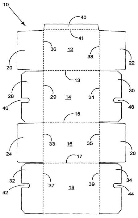
Turning to the first embodiment shown in Figure l, the blank 10 comprises a
plurality of
panels for forming the top, base and opposed side walls whereby there is shown
a top panel
12, a first side wall panel 14, bottom panel 16 and second side wall panel 18
hingedly
connected one to the next in series along fold lines 13, 15 and 17
respectively.
The ends of the carton are constructed by one or more end panels. In this
embodiment,
opposed end panels 20 and 22 are hingedly connected to the opposing ends of
top wall panel
12 along fold lines 36 and 38 respectively. A second pair of end panels 24, 26
is provided
along opposing end edges of base panel 16 and hingedly connected thereto along
fold lines 36
2o and 38 respectively.
Preferably, a pair of end flaps 28, 30 is hingedly connected to first side
wall panel 14 along
opposing end edges and are connected thereto by fold lines 36, 38
respectively. Likewise, a
second pair of end flaps 32, 34 are hingedly connected to side wall panel 18
along fold lines
36, 38 respectively. The end panels 20, 22; 32, 34 are usually secured to the
end flaps, so that
in use, the end flaps support the end walls to improve rigidity.
There may further comprise one or more recesses struck from end flaps. In use,
the recess
enables the insert structure I (Figure 4) to be secured to one or more of the
end panels 20, 24,
3o described below. In this embodiment, a pair of recesses 42, 46 are provided
in end flaps 28,
32 that are positioned in corresponding positions along the opposing side
edges, so as to
CA 02454630 2003-02-10
WO 02/14166 PCT/USO1/24698
_7_
marry up when the carton is erected. Preferably, a second pair or recesses 44,
48 is applied to
the opposing end flaps 30, 34 so that the insert structure can be inserted
from either end to be
secured to the outer carton described in more detail below.
It is envisaged that the recess is not limited to the shape illustrated in
Figure l and indeed
could be replaced by other means to allow the insert structure to juxtapose
the end panel. For
example, end flap 28 could terminate at the lower edge of recess 46 or,
alternatively one or
more apertures could be struck from end flaps 28 and/or 32.
l0 Turning to the construction of the insert structure, there comprises a
blank 50, as shown in
Figure 2, comprising one or more medial partition panels and a securing panel.
There further
comprises at least one transverse partition panel. Therefore, for a carton
holding a group of
four articles in a 2 x 2 arrangement, a single medial panel and transverse
partition panel is
required together with the end panel. Other arrangements are envisaged, so
that for three
15 rows of articles, two medial partition panels are provided.
In the illustrated embodiment, there comprises a first medial partition panel
52, an end panel
54 and second medial partition panel 56 hingedly connected together along fold
lines 58 and
60 and adapted to receive twelve articles in a 3 x 4 arrangement.
Figure 2 shows medial partition panel 52 is provided with three transverse
partition panels
62a, 62b and 62c. Each transverse partition panel is similar and therefore
only partition panel
62a is described in any greater detail.
Transverse partition panel 62a is connected to medial partition panel 52 along
upper and
lower fold lines 66a and 68a to create a panel that extends outwardly from
both sides of the
medial panel 52. It will be seen from Figure 2 that, in this embodiment, fold
lines 66 and 68
are aligned in a vertical plane. The upper and lower edges of panel 62a are
adapted to extend
one side of the medial panel are defined by cut lines 76 and 78 respectively
which separate
3o the panel 62a from medial panel 52. Cut line 76 extends from the lower end
of fold line 66 to
the upper end of the upper fold line 66b connecting panel 62b to medial panel
52. Similarly,
CA 02454630 2003-02-10
WO 02/14166 PCT/USO1/24698
_g_
cut line 78 extends from the upper end of fold line 68 to the lower end of the
lower fold line
connecting panel 62b to medial panel 52.
Further cut lines 77 and 79 define respectively the upper and lower edges of
the part of the
transverse partition panel that will extend outwardly from the other side of
the medial panel
52. The opposing side edges of transverse partition panel 62a are provided by
cut lines 72
and 74 respectively and optionally, apertures 70a, 70b.
Adjacent one of the side edges 74 of partition panel 62a, there comprises a
protruding portion
to 98 used to overlap the portion 96 of transverse panel 64a struck from the
other medial
partition panel 56 and described in more detail below.
The second medial partition panel is also provided with three transverse
partition panels 64a,
64b and 64c. It will be seen that each transverse partition panel is similar
and therefore only
15 partition panel 64c is described in any greater detail.
Transverse partition panel 64c is similar to transverse partition panel 62a in
that it is
preferably adapted to extend outwardly on both sides of the medial panel 56.
Thus, panel 64a
is connected to medial partition panel 56 along fold lines 80c and 82c that
are aligned in a
20 ' vertical plane, in this embodiment. The upper and lower edges of panel
64a to extend one
side of the medial panel are defined by cut lines 86 and 87 respectively which
separate the
panel 64a from medial panel 56. Cut line 86 extends from the upper end of fold
line 82c to
the lower end of the upper fold line 82b connecting panel 64b to medial panel
56. Similarly,
cut line 87 extends from the lower end of fold line 80c to the upper end of
lower fold line 80b
25 connecting panel 64b to medial panel 56. A further cut line 84 is shaped to
define the part
that will extend outwardly from the other side of the medial panel 56. Cut
line 84 also
defines a protruding portion 96 used to overlap the portion 98 struck from the
transverse
panel 62c of other medial partition panel 52 and described in more detail
above.
3o There may further comprise a tab 92 and cut lines 90 extending from the end
edge of
transverse panel 64a. Additionally or alternatively, there may also comprise
apertures 70
CA 02454630 2003-02-10
WO 02/14166 PCT/USO1/24698
-9-
struck from medial panel 52. In use, they assist in causing the panels 62a,
64a to separate
from the medial panels 52 and 56 respectively.
A plurality of apertures 88, 94 struck from each of the transverse partition
panels 64a, 64b,
64c and a corresponding aperture 94 may be struck from end panel 54 may be
provided: they
are used by suitable machinery to open the transverse panels 64 during the
mechanical
construction of the insert structure.
Turning now to the second embodiment of the present invention, as illustrated
in Figures 6 to
13 which is similar to the first embodiment and therefore, like numerals have
been where
possible used to denote like parts with the addition of the prefix "1 ". Only
the differences
between the first and second embodiments will be described in any greater
detail.
In this embodiment, the recesses 142, 146 are provided at opposed and spaced
positions in
end flap 120, as shown in Figure 6. Furthermore the means to connect the outer
panel to the
insert structure is provided on one end of the carton only.
The blank is adapted to receive one or more articles, for example sachets and
to be displayed
within the caxton by means of a display window formed by recesses in end
panels 122 and
126. In order to gain access to the interior of the carton an access structure
is provided, which
in this embodiment is provided by a plurality of frangible lines. The
frangible lines 101, 104,
102, and 108 are formed in the panels 134, 118, 120, 114 and 130 to define a
removable
cover. The cover is provided by panels 147 and 145 as well as end flap 122 top
panel 112
and part of end flap 120. To assist in removing the cover an aperture and
finger tab 143 are
provided in end flap 120.
In some embodiments the cover is provided with a fold line 106, which is used
to partially
fold back the cover to reveal the contents of the carton.
The insert structure 150 is illustrated in Figure 7 and are placed
intermediate the outer edges
of the sachets and the outer walls to provide extra protection. In this
embodiment there are
CA 02454630 2003-02-10
WO 02/14166 PCT/USO1/24698
- 10-
opposed medial panels 152 and 156 and securing panel 154 hingedly connected
together
along fold lines 158 and 160, as shown in Figure 7.
Turning now to the third embodiment of the present invention, as illustrated
in Figures 14 to
18 which is similar to the first embodiment and therefore, like numerals have
been where
possible used to denote like parts with the addition of the prefix "2". Only
the differences
between the first and third embodiments will be described in any greater
detail.
It will be seen from Figure 14 that the construction of the end panels 224,
226; 220, 222 and
to end flaps 232, 234; 228, 230 is very similar to the first embodiment. The
principal difference
is that in this embodiment there is provided a handle structure. The handle is
struck from top
panel 212 by opposed cut lines 227a, 227b; 261 a, 261b; 229a, 229b to define a
handle strip H
and is hingedly connected thereto along fold lines proximate a central portion
of top panel
212.
Preferably the handle strip H extends into the adjacent side or end walls. In
this embodiment,
the handle strip extends into side wall panels 218 and 214 and is hingedly
connected thereto
along fold lines 221 and 223 respectively. The handle strip is separated from
side wall panels
218 and 214 by extensions of cut lines 227 and 229 respectively that terminate
at the ends of
fold lines 221 and 223. There may further comprise hand support flaps 265
hingedly
connected to opposed side edges of handle strip H.
The insert blank 250 is illustrated in Figure 15 and, again, is placed
intermediate the outer
edges of the sachets and the outer walls to provide extra protection. In this
embodiment there
are opposed medial panels 252 and 256 and securing panel 254 hingedly
connected together
along fold lines 258 and 260, as shown in Figure 15.
The insert blank 250 is also provided with additional flaps 251 and 257. In
use the flaps
envelop the sachets to be held in position as they are loaded into the carton.
CA 02454630 2003-02-10
WO 02/14166 PCT/USO1/24698
-11-
Turning to the construction of the carton from any of the carton blanks
illustrated in Figures
1, 6 or 14 and the insert structure from the insert blanks illustrated in
Figure 2, 7 or 15 each
blank requires a series of sequential folding and gluing operations which are
preferably
performed in a straight line machine, so that the carton and blank are not
required to be
rotated or inverted to complete its construction. The folding process is not
limited to that
described below and can be altered according to particular manufacturing
requirements.
Dealing with the construction of the insert structure I of the first
embodiment from the blank
50, shown in Figure 2, the medial partition panels 52 and 56 are folded out of
alignment from
1o securing panel 54 along fold lines 58, 60 to be placed in a substantially
perpendicular
arrangement, whereby the medial partition panels 52 and 56 are substantially
parallel and in a
spaced arrangement. To construct the individual cells O (shown in Figure 3),
the transverse
partition panels 62 and 64 are moved out of alignment with medial partition
panels 52 and 56
respectively. Turning first to transverse partition panel 62c, the panel is
folded along fold
15 lines 66c and 68c so that the protruding portion 98 is folded inwardly on
one side of the
medial panel 52. It will be seen that the transverse partition panel 62c is
caused to pivot
about fold lines 66c and 68c so that the panel extends from both sides of the
medial panel 52.
Preferably, the transverse partition panel 62c is substantially perpendicular
to the medial
panel 52. Likewise, transverse partition panels 62a and 62b are formed in a
like manner.
Transverse partition panels 64a, 64b, 64c are formed in a like manner whereby
panel 64c is
folded out of alignment with medial panel 56 along fold lines 80c and 82c and
is caused to
pivot so that the transverse panel 64c extends from both sides of the medial
panel 56 in a
substantially perpendicular relationship with respect to it. Protruding
portion 96 extends
inwardly and comes into abutment with corresponding protruding portion 98.
Preferably, the
corresponding protruding parts 96, 98 are secured together by glue or other
suitable means
known in the art which creates a rigid insert structure I. Panels 64b and 64a
are formed in a
like manner and shall therefore not be described in any greater detail. Thus,
the insert
structure is in a set up condition as shown in Figure 3. It will be seen that
there are twelve
3o cells O formed to separate and support the articles in adjacent cells.
CA 02454630 2003-02-10
WO 02/14166 PCT/USO1/24698
-12-
The insert structure I is ready to receive the articles, which are loaded by
relative vertical
movement between the articles A and the insert structure I during forward feed
movement.
The articles enter their respective cells through the open bottom of the
insert structure.
Alternatively, the articles can enter their respective cells through the top
of the insert structure
I.
The outer carton C is constructed by folding top panel 12, first side wall
panel 14, base panel
16 and second side wall panel 18 out of alignment with each other along fold
lines 13, 15 and
17 to be folded into a tubular structure, shown in Figure 4. Top panel 12 and
side panel 18
to are secured together by securing flap 40. In those embodiments with
securing flap 40, it is
secured to side panel 18 by folding along fold line 41 to be secured to the
side panel 18 by
glue or other suitable means known in the art.
The carton is at an intermediate stage of construction whereby the articles
and insert structure
15 are inserted into the carton C from one of the ends. It will be seen from
Figure 4 that the end
panels 20 and 24 and end flaps 28 and 32 are folded outwardly along fold line
36 to guide the
articles and insert structure into the carton. Preferably, the opposing end
wall is formed prior
to receiving the articles whereby end flaps 30 and 34 are folded inwardly
along fold lines 31
and 39 respectively. Thereafter, end wall panels 22 and 26 are folded inwardly
along fold
20 lines 35 and 38 to be secured to the end flaps 30 and 32 by glue or other
suitable means
known in the art. Thus, the carton is at the stage illustrated in Figure 4.
In order to complete construction of the carton C, the insert structure I
should be secured to
one of the end wall panels 20 or 24. To this end, the end flaps 28 and 32 are
folded inwardly
25 along fold line 36 so that a portion of the end flaps 28, 32 come into
abutment with the end
wall 54 of insert structure I, and the recesses 42 and 46 are aligned, as
shown in Figure 5.
End wall panel 20 is folded downwardly along fold line 36 and is, optionally,
secured to the
end flaps 28 and 32 by glue or other suitable means known in the art.
Alternatively, the end
3o wall 20 is held in place by end wall panel 24, which is secured to the end
flaps described
below. Thereafter, the lower end wall panel 24 is folded inwardly along fold
line 33 and
CA 02454630 2003-02-10
WO 02/14166 PCT/USO1/24698
-13-
secured to the end flaps 28 and 32 by glue, such as glue strip G2, or other
suitable means
known in the art. In order to secure the insert structure I to end wall panel
24, a strip of glue
G1 is, in this embodiment, applied in a substantially straight line
intermediate opposing side
edges of the end flaps such that the glue is applied through recesses 42, 46
to the insert
structure.
In alternative embodiments, glue may be applied to different areas of the
blank such as where
apertures are used instead of the recess. By folding the end wall panel 24
inwardly, it is
secured in face contacting relationship with the end flaps 28 and 32 and, the
part of the insert
to structure I revealed by the recesses 42, 46. In this way, the insert
structure I is secured
directly to an outer wall of the carton by the application of glue in a
standard method i.e.
using a straight line gluing gun. Thus, the carton is in a set up condition.
The construction of the carton of the second embodiment is similar to the
first embodiment in
15 that the outer carton C is constructed by folding top panel 112, first side
wall panel 114, base
panel 116 and second side wall panel 118 out of alignment with each other
along fold lines
113, 115 and 117 to be folded into a tubular structure, shown in Figure 8.
Base panel 116 and
side panel 18 are secured together. In those embodiments with securing flap
140, it is secured
to side panel 118 by folding along fold line 142 to be secured thereto by glue
or other suitable
2o means known in the art.
The insert structure is inserted into the carton, as shown in Figure 8, which
helps to brace the
outer carton and maintain it in a set up condition. Thereafter the articles
are loaded into the
carton and the end flaps 130 and 134 and end panels 122, 126 are folded
inwardly and
25 secured together to define a display window, as shown in Figure 9.
Figure 10 shows the opposing end wall formed in like manner to the first
embodiment
whereby end wall panel 120 is folded downwardly along fold line 136 and is,
optionally,
secured to the end flaps 128 and 132 by glue or other suitable means known in
the art.
3o Thereafter, the lower end wall panel 124 is folded inwardly along fold line
133 and secured to
the end flaps 128 and 132 by glue, such as glue portions G, or other suitable
means known in
CA 02454630 2003-02-10
WO 02/14166 PCT/USO1/24698
-14-
the art. In order to secure the insert structure to end wall panel 124, a
strip of glue G is, in
this embodiment, applied in a substantially straight line intermediate
opposing side edges of
the end flaps such that the glue is applied through recesses 42, 46 to the
insert structure.
By folding the end wall panel 124 inwardly, it is secured in face contacting
relationship with
the end flaps 128 and 132 and, the part of the insert structure revealed by
the recesses 142,
146. In this way, the insert structure is secured directly to an outer wall of
the carton by the
application of glue in a standard method i.e. using a straight line gluing
gun. Thus, the carton
is in a set up condition as shown in Figure 11.
to
In order to remove the cover to gain access to the interior of the carton, as
shown in Figures
12 and 13, the user pulls on the pull tab and tears the cover from the carton
by tearing along
the frangible lines 102, 113, 115, 104, 108, 101 and 103, to separate it as
shown in Figure 13,
thereby to reveal the articles A.
Turning to the third embodiment illustrated in Figures 16, the outer carton is
formed and
loaded in an identical manner to that described above. In this embodiment the
insert structure
is attached to the outer panels of the end walls at each end. This is achieved
by the provision
of flaps, 251 and 257 which appear through the recesses 242, 246, as shown in
Figure 17.
2o Thereafter the end wall 226 is secured directly to one or both of panels
251, 257 by the
application of glue in a standard method.
The handle is constructed when the user pushes the hand flaps inwardly to
reveal the handle
strip shown in Figure 18. Lifting the handle strip will separate it from the
top and side walls
because of the cut lines 227, 229 and 261. The handle strip is hinged to the
top panel 212 by
step panels 267, which pivot about their hinged connections between the handle
strip H and
the side walls 218 and 214 to dissipate some of the load from lifting the
handle.
1n order to gain access to the interior of the carton shown in Figure 19,
there is provided a
3o cover panel struck from top panel 212 and hinged to end wall panel 222.
Cover panel is
CA 02454630 2003-02-10
WO 02/14166 PCT/USO1/24698
-15-
frangibly connected to top and side walls by frangible lines 227, 229 and 225
which separates
it from the respective panels to reveal the articles contained in the carton.
The present invention and its preferred embodiment relates to an arrangement
for securing
together the outer end panels and at least one panel of an insert structure,
however it is
anticipated that the invention can be applied to a variety of carriers and is
not limited to those
of the fully enclosed type hereinabove described and could be used for
numerous applications
where it is desired to secure a separate blank to an outer carton in a face
contacting
relationship in which a single application of glue is used.
It will be recognised that as used herein, directional references such as
"top", "base", "end",
"side", "inner", "outer", "upper" and "lower" do not limit the respective
panels to such
orientation, but merely serve to distinguish these panels from one another.
Any reference to
hinged connection should not be construed as necessarily referring to a single
fold line only:
indeed it is envisaged that hinged connection can be formed from one or more
of one of the
following, a score line, a frangible line or a fold line, without departing
from the scope of
invention.
It should be understood that various changes may be made within the scope of
the present
2o invention, for example, the size and shape of the panels and apertures may
be adjusted to
accommodate articles of differing size or shape, alternative top and base
closure structures
may be used. A single glue aperture may be provided in some embodiments. The
carton may
accommodate more than one article in different arrays. Additional panels) may
be provided
between the main and transverse article receiving panels so as to form a
curved interface there
between.