Language selection

Search

Patent 2454855 Summary

Third-party information liability

Some of the information on this Web page has been provided by external sources. The Government of Canada is not responsible for the accuracy, reliability or currency of the information supplied by external sources. Users wishing to rely upon this information should consult directly with the source of the information. Content provided by external sources is not subject to official languages, privacy and accessibility requirements.

Claims and Abstract availability

Any discrepancies in the text and image of the Claims and Abstract are due to differing posting times. Text of the Claims and Abstract are posted:

  • At the time the application is open to public inspection;
  • At the time of issue of the patent (grant).
(12) Patent Application: (11) CA 2454855
(54) English Title: A TERMINAL HINGE FOR LIFT TRUCKS HAVING TELESCOPIC ARMS
(54) French Title: CHARNIERE TERMINALE POUR CHARIOTS ELEVATEURS A BRAS TELESCOPIQUES
Status: Deemed Abandoned and Beyond the Period of Reinstatement - Pending Response to Notice of Disregarded Communication
Bibliographic Data
(51) International Patent Classification (IPC):
  • B66F 09/16 (2006.01)
  • B66F 09/065 (2006.01)
(72) Inventors :
  • MAGNI, RICCARDO (Italy)
(73) Owners :
  • MANITOU COSTRUZIONI INDUSTRIALI S.R.L.
(71) Applicants :
  • MANITOU COSTRUZIONI INDUSTRIALI S.R.L. (Italy)
(74) Agent: SMART & BIGGAR LP
(74) Associate agent:
(45) Issued:
(22) Filed Date: 2003-12-30
(41) Open to Public Inspection: 2004-07-30
Examination requested: 2008-12-29
Availability of licence: N/A
Dedicated to the Public: N/A
(25) Language of filing: English

Patent Cooperation Treaty (PCT): No

(30) Application Priority Data:
Application No. Country/Territory Date
IT-MO2003A000021 (Italy) 2003-01-30

Abstracts

English Abstract


The hinge comprises a first link element and a second link element hinged to
a free end of a telescopic arm of the lift truck. The first link element is
commanded to oscillate about a hinge axis by first means for actuating acting
between the free end and the first link element. The second link element,
which supports a quick-release mechanism for a tool, is commanded to
oscillate about the same hinge axis by second means for actuating acting
between the first link element and the second link element.


Claims

Note: Claims are shown in the official language in which they were submitted.

-5-
WHAT is CLAIMED.
1). A terminal hinge fox lift trucks having telescopic arms, comprising a
first
link element and a second link element hinged to a free end of a telescopic
arm
of the lift truck, the first link element being commanded to oscillate about a
hinge axis by first means for actuating acting between the free end and the
first
link element; the second link element, which supports a quick-release
mechanism for a tool, being commanded to oscillate about the hinge axis by
second means for actuating acting between the first link element and the
second link element.
2). The hinge of claim 1, wherein the first means for actuating comprise at
least a first hydraulic jack having a cylinder hinged to the telescopic arm
and
an end of a stem hinged to the first link element.
3). The hinge of claim 2, wherein the second means for actuating comprise at
least a second hydraulic jack having a cylinder hinged to the first link
element
and an end of a stem hinged to the second link element.
4). The hinge of claim 3, wherein the cylinder of the second hydraulic jack is
hinged to the first link element about an axis which is in proximity of a
hinge
axis of the end of the stem of the first hydraulic cylinder.
5). The hinge of claim 4, wherein the hinge axis lies in a perpendicular plane
to an axis of the telescopic arm.
6). The hinge of claim 5,wherein the first link element comprises two plates
which face one another and which are connected to one another by a crossbar
arranged perpendicular to the two plates, the two plates being coupled in


-6-
rotation to the free end of the telescopic arm by a first transversal pivot
which
first transversal pivot is coaxial to the hinge axis; and the two plates being
coupled to the end of the stem of the first hydraulic jack by a second
transversal pivot.
7). The hinge of claim 6, wherein the second link element comprises two
curved plates which face one another and which are connected to one another
by a crossbar arranged perpendicular to the two curved plates, the two curved
plates being coupled in rotation to the free end of the telescopic arm by the
first transversal pivot which first transversal pivot is coaxial to the hinge
axis;
the two curved plates exhibiting concavities predisposed at least partially to
embrace the crossbar of the first link element in a position in which the stem
of the second hydraulic jack is retracted.
8). The hinge of claim 7, wherein the second means for actuating comprise two
of the second hydraulic jack, each having the cylinder hinged to a respective
plate of the two plates of the first link element by coaxial first pivots, and
the
end of the stem is hinged to a respective curved plate of the second link
element by coaxial second pivots.
9). The hinge of claim 8,wherein the first pivots are coaxial to the second
transversal pivot.

Description

Note: Descriptions are shown in the official language in which they were submitted.


CA 02454855 2003-12-30
A TERMINAL HINGE FOR LIFT TRUCKS HAVING TELESCOPIC ARMS.
BACKGROUND of the INVENTION.
Lift trucks with telescopic arm comprises a vehicle which at one end support
a terminal part of a telescopic arm rotating on a vertical plane between a
horizontal position and a practically vertical position. At a free end of the
telescopic arm a quick-release tool is mounted, typically a forked support
frame for raising loads on pallets from the truck level to higher levels, for
example upper floors of a building. The quick-release mechanism is
associated to the free end of the telescopic arm by means of a hinge which
enables the tool to rotate on a vertical plane and has the aim of keeping the
forks of the frame horizontal in all positions assumed by the telescopic arm.
1 o The range of oscillation of the support frame is therefore rather limited,
which
in turn limits the range of use of the lift truck to loading and raising
operations
of palletized loads with fork support frames: In particular, it is not
practicable
to use, for example, front loaders, which can substitute the frame very
quickly
thanks to the quick-release mechanism, and which can be used to load loose
materials; it is impracticable because it is impossible to rotate and keep the
mouth of the loader in an upwards-facing direction. For similar reasons, use
of a forked support frame can be made safely only when the pallets to be
raised
are well balanced and bound, as the support frame cannot be rotated
sufficiently to bring the forks into a position of safety, i.eo inclined
upwards.
2o° SUMMARY of the INVENTION.
The main aim of the present invention is to obviate the above-described
drawbacks by providing a terminal hinge for lift trucks having telescopic arms
which enables wide tool mobility in order that the truck can be used for a

CA 02454855 2003-12-30
-2-
broad range of applications; in particular the tool can be rotated on a plane
of
over 90°.
BRIEF DESCRIPTION of the DRAWINGS.
Further characteristics and advantages of the present invention will better
emerge from the detailed description that follows of a terminal hinge for lift
trucks having telescopic arms, illustrated purely by way of a non-limiting
example in the accompanying figures of the drawings, in which:
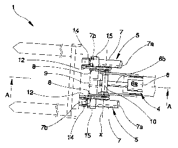
figure 1 is a plan view of a hinge according to the present invention;
figure 1 a is a view in section of the hinge of figure 1, according to Iine A-
A;
1 o figure 2 is the hinge of figure 1 a in a maximum extension position;
figure 3 is the hinge of figure 1 a in an intermediate extension position;
figure 4 is the hinge of figure 1 a in a closed configuration.
DESCRIPTION of the PREFERRED EMBODIMENTS.
With reference to the figures of the drawings, 1 denotes in its entirety a
hinge
according to the present invention. It comprises a first link element 2 and a
second link element 3 hinged to a free end 22 of the telescopic arm 21 of the
lift truck 20. The first link element 2 is commanded to oscillate about a
hinge
aXis x by first means for actuating 4 which act between the free end 22 and
the
first link element 2. 'The second link element 3, which supports a quick-
release
2o mechanism 23 for a tool, is commanded to oscillate about the same hinge
axis
x by second means for actuating 5 which act between the first link element 2
and the second link element 3. The hinge axis x lies in a perpendicular axis
to
the axis of the telescopic arm 21.
' The first means for actuating 4 comprise at least a first hydraulic jack 6
which
exhibits a cylinder 6a which is hinged to the telescopic arm 21 and an end of
a stem 6b which is hinged to the first Iink element 2.
The second means for actuation 5 comprise at least a second hydraulic j ack 7

CA 02454855 2003-12-30
-3-
which exhibits a cylinder 7a hinged to the first link element 2 and an end of
a
stem 7b which is hinged to the second link element 3. The second hydraulic
jack 7 is hinged to the first link element 2 about an axis which is close to
the
hinge axis of the end of the stem 6b of the first hydraulic jack 6.
The first link element 2 comprises two plates 8, reciprocally facing and
connected to one another by a crossbar 9 arranged perpendicular to the two
plates 8. The two plates 8 are coupled in rotation to the free end 22 of the
telescopic arm 21 by a first transversal pivot 10 which is coaxial to the
hinge
axis x, and the two plates are also coupled to the end of the stem 6b of the
fzrst
to hydraulic jack 6 by a second transversal pivot I 1.
The second link element 3 comprises two curved plates I2 which face one
another and which are connected one to another by a crossbar 13 arranged
perpendicular to the two curved plates 12. The two curved plates 12 are
coupled in xotation to the free end 22 of the telescopic arm 21 by the first
transversal pivot 10 coaxial to the hinge axis x, and the curved part is
predisposed to embrace, at least partially, the crossbar 9 of the first link
element 2 in a position in which the stem 7b of the second hydraulic jack 7 is
in a retracted position. The curved shape of the curved plates 12 enables the
second link element 3, when the stem '7b of the second hydraulic jack 7 is
2o retracted inside the cylinder 7a, to be positioned at least partially
within the
space of the first link element 2, resulting in a particularly compact
configuration.
In the illustrated embodiment the second means for actuation 5 are two of the
second hydraulic jack 7, having cylinders thereof hinged to a respective plate
8 of the first link element by coaxial first pivots I5, and having ends of the
stems thereof hinged to a respective curved plate 12 of the second link
element
3 by coaxial second pivots 14. Advantageously the first pivots 15 are coaxial

CA 02454855 2003-12-30
_4_
to the second transversal pivot l 1 in order to limit a surface of the plates
8 of
the first link element 2 and to increase a compactness of the hinge.
The hinge operates in an extremely simple and rational way. Starting from a
"closed" configuration, such as the one illustrated in figure 3, the first
hydraulic jack 6 rotates the first link element 2 about the pivot 10 by an
angle
of about 135° (figure 2), which angle is sufficient to enable a safe
transport of
a not-particularly well-balanced or compact pallet:. Then, resuming from the
configuration of figure 2, by extending the second hydraulic jack 7 or jacks,
the second link element 3 can be xotated about the pivot 10 by and angle of
about 45°, during which the quick-release mechanism 23 rotates by about
180°. The two above-described rotations can be synchronized or
commanded
independently to enable maximum flexibility of action.
The hinge ofthe present invention provides important advantages. Firstly, the
tool attached to the end of the telescopic arm ha's a broad range of mobility,
decidedly greater than hinges at present available. The architecture of the
hinge
is particularly compact and rigid, enabling use of tools of various types and
of
different dimensions.
Advantageously front loaders can be mounted on the quick-release mechanism
for raising and lowering loose materials, as it is possible, thanks to the
mobility
of the hinge of the present invention, to rotate and maintain the mouth of the
loader in an upwards-facing position. This advantage is also valid for forked
support frames for moving pallets which are not well-balanced and bound, as
the support frame can be rotated into a safety position in vc%hich the forks
have
their ends facing upwards.

Representative Drawing
A single figure which represents the drawing illustrating the invention.
Administrative Status

2024-08-01:As part of the Next Generation Patents (NGP) transition, the Canadian Patents Database (CPD) now contains a more detailed Event History, which replicates the Event Log of our new back-office solution.

Please note that "Inactive:" events refers to events no longer in use in our new back-office solution.

For a clearer understanding of the status of the application/patent presented on this page, the site Disclaimer , as well as the definitions for Patent , Event History , Maintenance Fee  and Payment History  should be consulted.

Event History

Description Date
Application Not Reinstated by Deadline 2012-09-11
Inactive: Dead - No reply to s.30(2) Rules requisition 2012-09-11
Deemed Abandoned - Failure to Respond to Maintenance Fee Notice 2011-12-30
Inactive: Abandoned - No reply to s.30(2) Rules requisition 2011-09-12
Inactive: S.30(2) Rules - Examiner requisition 2011-03-11
Letter Sent 2009-02-12
All Requirements for Examination Determined Compliant 2008-12-29
Request for Examination Received 2008-12-29
Request for Examination Requirements Determined Compliant 2008-12-29
Inactive: IPC from MCD 2006-03-12
Application Published (Open to Public Inspection) 2004-07-30
Inactive: Cover page published 2004-07-29
Inactive: First IPC assigned 2004-04-23
Inactive: Filing certificate - No RFE (English) 2004-02-20
Letter Sent 2004-02-20
Application Received - Regular National 2004-02-20

Abandonment History

Abandonment Date Reason Reinstatement Date
2011-12-30

Maintenance Fee

The last payment was received on 2010-11-02

Note : If the full payment has not been received on or before the date indicated, a further fee may be required which may be one of the following

  • the reinstatement fee;
  • the late payment fee; or
  • additional fee to reverse deemed expiry.

Patent fees are adjusted on the 1st of January every year. The amounts above are the current amounts if received by December 31 of the current year.
Please refer to the CIPO Patent Fees web page to see all current fee amounts.

Fee History

Fee Type Anniversary Year Due Date Paid Date
Registration of a document 2003-12-30
Application fee - standard 2003-12-30
MF (application, 2nd anniv.) - standard 02 2005-12-30 2005-10-27
MF (application, 3rd anniv.) - standard 03 2007-01-01 2006-11-14
MF (application, 4th anniv.) - standard 04 2007-12-31 2007-11-06
MF (application, 5th anniv.) - standard 05 2008-12-30 2008-11-20
Request for examination - standard 2008-12-29
MF (application, 6th anniv.) - standard 06 2009-12-30 2009-11-04
MF (application, 7th anniv.) - standard 07 2010-12-30 2010-11-02
Owners on Record

Note: Records showing the ownership history in alphabetical order.

Current Owners on Record
MANITOU COSTRUZIONI INDUSTRIALI S.R.L.
Past Owners on Record
RICCARDO MAGNI
Past Owners that do not appear in the "Owners on Record" listing will appear in other documentation within the application.
Documents

To view selected files, please enter reCAPTCHA code :


To view images, click a link in the Document Description column (Temporarily unavailable). To download the documents, select one or more checkboxes in the first column and then click the "Download Selected in PDF format (Zip Archive)" or the "Download Selected as Single PDF" button.

List of published and non-published patent-specific documents on the CPD .

If you have any difficulty accessing content, you can call the Client Service Centre at 1-866-997-1936 or send them an e-mail at CIPO Client Service Centre.

({010=All Documents, 020=As Filed, 030=As Open to Public Inspection, 040=At Issuance, 050=Examination, 060=Incoming Correspondence, 070=Miscellaneous, 080=Outgoing Correspondence, 090=Payment})


Document
Description 
Date
(yyyy-mm-dd) 
Number of pages   Size of Image (KB) 
Description 2003-12-29 4 239
Claims 2003-12-29 2 91
Abstract 2003-12-29 1 20
Drawings 2003-12-29 4 102
Representative drawing 2004-05-03 1 13
Courtesy - Certificate of registration (related document(s)) 2004-02-19 1 107
Filing Certificate (English) 2004-02-19 1 160
Reminder of maintenance fee due 2005-08-30 1 110
Reminder - Request for Examination 2008-09-02 1 118
Acknowledgement of Request for Examination 2009-02-11 1 176
Courtesy - Abandonment Letter (R30(2)) 2011-12-04 1 166
Courtesy - Abandonment Letter (Maintenance Fee) 2012-02-23 1 172
Fees 2005-10-26 1 27
Fees 2006-11-13 1 29
Fees 2007-11-05 1 30
Fees 2008-11-19 1 35
Fees 2009-11-03 1 37
Fees 2010-11-01 1 37