Sélection de la langue

Search

Sommaire du brevet 2454855 

Énoncé de désistement de responsabilité concernant l'information provenant de tiers

Une partie des informations de ce site Web a été fournie par des sources externes. Le gouvernement du Canada n'assume aucune responsabilité concernant la précision, l'actualité ou la fiabilité des informations fournies par les sources externes. Les utilisateurs qui désirent employer cette information devraient consulter directement la source des informations. Le contenu fourni par les sources externes n'est pas assujetti aux exigences sur les langues officielles, la protection des renseignements personnels et l'accessibilité.

Disponibilité de l'Abrégé et des Revendications

L'apparition de différences dans le texte et l'image des Revendications et de l'Abrégé dépend du moment auquel le document est publié. Les textes des Revendications et de l'Abrégé sont affichés :

  • lorsque la demande peut être examinée par le public;
  • lorsque le brevet est émis (délivrance).
(12) Demande de brevet: (11) CA 2454855
(54) Titre français: CHARNIERE TERMINALE POUR CHARIOTS ELEVATEURS A BRAS TELESCOPIQUES
(54) Titre anglais: A TERMINAL HINGE FOR LIFT TRUCKS HAVING TELESCOPIC ARMS
Statut: Réputée abandonnée et au-delà du délai pour le rétablissement - en attente de la réponse à l’avis de communication rejetée
Données bibliographiques
(51) Classification internationale des brevets (CIB):
  • B66F 09/16 (2006.01)
  • B66F 09/065 (2006.01)
(72) Inventeurs :
  • MAGNI, RICCARDO (Italie)
(73) Titulaires :
  • MANITOU COSTRUZIONI INDUSTRIALI S.R.L.
(71) Demandeurs :
  • MANITOU COSTRUZIONI INDUSTRIALI S.R.L. (Italie)
(74) Agent: SMART & BIGGAR LP
(74) Co-agent:
(45) Délivré:
(22) Date de dépôt: 2003-12-30
(41) Mise à la disponibilité du public: 2004-07-30
Requête d'examen: 2008-12-29
Licence disponible: S.O.
Cédé au domaine public: S.O.
(25) Langue des documents déposés: Anglais

Traité de coopération en matière de brevets (PCT): Non

(30) Données de priorité de la demande:
Numéro de la demande Pays / territoire Date
IT-MO2003A000021 (Italie) 2003-01-30

Abrégés

Abrégé anglais


The hinge comprises a first link element and a second link element hinged to
a free end of a telescopic arm of the lift truck. The first link element is
commanded to oscillate about a hinge axis by first means for actuating acting
between the free end and the first link element. The second link element,
which supports a quick-release mechanism for a tool, is commanded to
oscillate about the same hinge axis by second means for actuating acting
between the first link element and the second link element.

Revendications

Note : Les revendications sont présentées dans la langue officielle dans laquelle elles ont été soumises.


-5-
WHAT is CLAIMED.
1). A terminal hinge fox lift trucks having telescopic arms, comprising a
first
link element and a second link element hinged to a free end of a telescopic
arm
of the lift truck, the first link element being commanded to oscillate about a
hinge axis by first means for actuating acting between the free end and the
first
link element; the second link element, which supports a quick-release
mechanism for a tool, being commanded to oscillate about the hinge axis by
second means for actuating acting between the first link element and the
second link element.
2). The hinge of claim 1, wherein the first means for actuating comprise at
least a first hydraulic jack having a cylinder hinged to the telescopic arm
and
an end of a stem hinged to the first link element.
3). The hinge of claim 2, wherein the second means for actuating comprise at
least a second hydraulic jack having a cylinder hinged to the first link
element
and an end of a stem hinged to the second link element.
4). The hinge of claim 3, wherein the cylinder of the second hydraulic jack is
hinged to the first link element about an axis which is in proximity of a
hinge
axis of the end of the stem of the first hydraulic cylinder.
5). The hinge of claim 4, wherein the hinge axis lies in a perpendicular plane
to an axis of the telescopic arm.
6). The hinge of claim 5,wherein the first link element comprises two plates
which face one another and which are connected to one another by a crossbar
arranged perpendicular to the two plates, the two plates being coupled in


-6-
rotation to the free end of the telescopic arm by a first transversal pivot
which
first transversal pivot is coaxial to the hinge axis; and the two plates being
coupled to the end of the stem of the first hydraulic jack by a second
transversal pivot.
7). The hinge of claim 6, wherein the second link element comprises two
curved plates which face one another and which are connected to one another
by a crossbar arranged perpendicular to the two curved plates, the two curved
plates being coupled in rotation to the free end of the telescopic arm by the
first transversal pivot which first transversal pivot is coaxial to the hinge
axis;
the two curved plates exhibiting concavities predisposed at least partially to
embrace the crossbar of the first link element in a position in which the stem
of the second hydraulic jack is retracted.
8). The hinge of claim 7, wherein the second means for actuating comprise two
of the second hydraulic jack, each having the cylinder hinged to a respective
plate of the two plates of the first link element by coaxial first pivots, and
the
end of the stem is hinged to a respective curved plate of the second link
element by coaxial second pivots.
9). The hinge of claim 8,wherein the first pivots are coaxial to the second
transversal pivot.

Description

Note : Les descriptions sont présentées dans la langue officielle dans laquelle elles ont été soumises.

CA 02454855 2003-12-30
A TERMINAL HINGE FOR LIFT TRUCKS HAVING TELESCOPIC ARMS.
BACKGROUND of the INVENTION.
Lift trucks with telescopic arm comprises a vehicle which at one end support
a terminal part of a telescopic arm rotating on a vertical plane between a
horizontal position and a practically vertical position. At a free end of the
telescopic arm a quick-release tool is mounted, typically a forked support
frame for raising loads on pallets from the truck level to higher levels, for
example upper floors of a building. The quick-release mechanism is
associated to the free end of the telescopic arm by means of a hinge which
enables the tool to rotate on a vertical plane and has the aim of keeping the
forks of the frame horizontal in all positions assumed by the telescopic arm.
1 o The range of oscillation of the support frame is therefore rather limited,
which
in turn limits the range of use of the lift truck to loading and raising
operations
of palletized loads with fork support frames: In particular, it is not
practicable
to use, for example, front loaders, which can substitute the frame very
quickly
thanks to the quick-release mechanism, and which can be used to load loose
materials; it is impracticable because it is impossible to rotate and keep the
mouth of the loader in an upwards-facing direction. For similar reasons, use
of a forked support frame can be made safely only when the pallets to be
raised
are well balanced and bound, as the support frame cannot be rotated
sufficiently to bring the forks into a position of safety, i.eo inclined
upwards.
2o° SUMMARY of the INVENTION.
The main aim of the present invention is to obviate the above-described
drawbacks by providing a terminal hinge for lift trucks having telescopic arms
which enables wide tool mobility in order that the truck can be used for a

CA 02454855 2003-12-30
-2-
broad range of applications; in particular the tool can be rotated on a plane
of
over 90°.
BRIEF DESCRIPTION of the DRAWINGS.
Further characteristics and advantages of the present invention will better
emerge from the detailed description that follows of a terminal hinge for lift
trucks having telescopic arms, illustrated purely by way of a non-limiting
example in the accompanying figures of the drawings, in which:
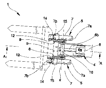
figure 1 is a plan view of a hinge according to the present invention;
figure 1 a is a view in section of the hinge of figure 1, according to Iine A-
A;
1 o figure 2 is the hinge of figure 1 a in a maximum extension position;
figure 3 is the hinge of figure 1 a in an intermediate extension position;
figure 4 is the hinge of figure 1 a in a closed configuration.
DESCRIPTION of the PREFERRED EMBODIMENTS.
With reference to the figures of the drawings, 1 denotes in its entirety a
hinge
according to the present invention. It comprises a first link element 2 and a
second link element 3 hinged to a free end 22 of the telescopic arm 21 of the
lift truck 20. The first link element 2 is commanded to oscillate about a
hinge
aXis x by first means for actuating 4 which act between the free end 22 and
the
first link element 2. 'The second link element 3, which supports a quick-
release
2o mechanism 23 for a tool, is commanded to oscillate about the same hinge
axis
x by second means for actuating 5 which act between the first link element 2
and the second link element 3. The hinge axis x lies in a perpendicular axis
to
the axis of the telescopic arm 21.
' The first means for actuating 4 comprise at least a first hydraulic jack 6
which
exhibits a cylinder 6a which is hinged to the telescopic arm 21 and an end of
a stem 6b which is hinged to the first Iink element 2.
The second means for actuation 5 comprise at least a second hydraulic j ack 7

CA 02454855 2003-12-30
-3-
which exhibits a cylinder 7a hinged to the first link element 2 and an end of
a
stem 7b which is hinged to the second link element 3. The second hydraulic
jack 7 is hinged to the first link element 2 about an axis which is close to
the
hinge axis of the end of the stem 6b of the first hydraulic jack 6.
The first link element 2 comprises two plates 8, reciprocally facing and
connected to one another by a crossbar 9 arranged perpendicular to the two
plates 8. The two plates 8 are coupled in rotation to the free end 22 of the
telescopic arm 21 by a first transversal pivot 10 which is coaxial to the
hinge
axis x, and the two plates are also coupled to the end of the stem 6b of the
fzrst
to hydraulic jack 6 by a second transversal pivot I 1.
The second link element 3 comprises two curved plates I2 which face one
another and which are connected one to another by a crossbar 13 arranged
perpendicular to the two curved plates 12. The two curved plates 12 are
coupled in xotation to the free end 22 of the telescopic arm 21 by the first
transversal pivot 10 coaxial to the hinge axis x, and the curved part is
predisposed to embrace, at least partially, the crossbar 9 of the first link
element 2 in a position in which the stem 7b of the second hydraulic jack 7 is
in a retracted position. The curved shape of the curved plates 12 enables the
second link element 3, when the stem '7b of the second hydraulic jack 7 is
2o retracted inside the cylinder 7a, to be positioned at least partially
within the
space of the first link element 2, resulting in a particularly compact
configuration.
In the illustrated embodiment the second means for actuation 5 are two of the
second hydraulic jack 7, having cylinders thereof hinged to a respective plate
8 of the first link element by coaxial first pivots I5, and having ends of the
stems thereof hinged to a respective curved plate 12 of the second link
element
3 by coaxial second pivots 14. Advantageously the first pivots 15 are coaxial

CA 02454855 2003-12-30
_4_
to the second transversal pivot l 1 in order to limit a surface of the plates
8 of
the first link element 2 and to increase a compactness of the hinge.
The hinge operates in an extremely simple and rational way. Starting from a
"closed" configuration, such as the one illustrated in figure 3, the first
hydraulic jack 6 rotates the first link element 2 about the pivot 10 by an
angle
of about 135° (figure 2), which angle is sufficient to enable a safe
transport of
a not-particularly well-balanced or compact pallet:. Then, resuming from the
configuration of figure 2, by extending the second hydraulic jack 7 or jacks,
the second link element 3 can be xotated about the pivot 10 by and angle of
about 45°, during which the quick-release mechanism 23 rotates by about
180°. The two above-described rotations can be synchronized or
commanded
independently to enable maximum flexibility of action.
The hinge ofthe present invention provides important advantages. Firstly, the
tool attached to the end of the telescopic arm ha's a broad range of mobility,
decidedly greater than hinges at present available. The architecture of the
hinge
is particularly compact and rigid, enabling use of tools of various types and
of
different dimensions.
Advantageously front loaders can be mounted on the quick-release mechanism
for raising and lowering loose materials, as it is possible, thanks to the
mobility
of the hinge of the present invention, to rotate and maintain the mouth of the
loader in an upwards-facing position. This advantage is also valid for forked
support frames for moving pallets which are not well-balanced and bound, as
the support frame can be rotated into a safety position in vc%hich the forks
have
their ends facing upwards.

Dessin représentatif
Une figure unique qui représente un dessin illustrant l'invention.
États administratifs

2024-08-01 : Dans le cadre de la transition vers les Brevets de nouvelle génération (BNG), la base de données sur les brevets canadiens (BDBC) contient désormais un Historique d'événement plus détaillé, qui reproduit le Journal des événements de notre nouvelle solution interne.

Veuillez noter que les événements débutant par « Inactive : » se réfèrent à des événements qui ne sont plus utilisés dans notre nouvelle solution interne.

Pour une meilleure compréhension de l'état de la demande ou brevet qui figure sur cette page, la rubrique Mise en garde , et les descriptions de Brevet , Historique d'événement , Taxes périodiques et Historique des paiements devraient être consultées.

Historique d'événement

Description Date
Demande non rétablie avant l'échéance 2012-09-11
Inactive : Morte - Aucune rép. dem. par.30(2) Règles 2012-09-11
Réputée abandonnée - omission de répondre à un avis sur les taxes pour le maintien en état 2011-12-30
Inactive : Abandon. - Aucune rép dem par.30(2) Règles 2011-09-12
Inactive : Dem. de l'examinateur par.30(2) Règles 2011-03-11
Lettre envoyée 2009-02-12
Toutes les exigences pour l'examen - jugée conforme 2008-12-29
Requête d'examen reçue 2008-12-29
Exigences pour une requête d'examen - jugée conforme 2008-12-29
Inactive : CIB de MCD 2006-03-12
Demande publiée (accessible au public) 2004-07-30
Inactive : Page couverture publiée 2004-07-29
Inactive : CIB en 1re position 2004-04-23
Inactive : Certificat de dépôt - Sans RE (Anglais) 2004-02-20
Lettre envoyée 2004-02-20
Demande reçue - nationale ordinaire 2004-02-20

Historique d'abandonnement

Date d'abandonnement Raison Date de rétablissement
2011-12-30

Taxes périodiques

Le dernier paiement a été reçu le 2010-11-02

Avis : Si le paiement en totalité n'a pas été reçu au plus tard à la date indiquée, une taxe supplémentaire peut être imposée, soit une des taxes suivantes :

  • taxe de rétablissement ;
  • taxe pour paiement en souffrance ; ou
  • taxe additionnelle pour le renversement d'une péremption réputée.

Les taxes sur les brevets sont ajustées au 1er janvier de chaque année. Les montants ci-dessus sont les montants actuels s'ils sont reçus au plus tard le 31 décembre de l'année en cours.
Veuillez vous référer à la page web des taxes sur les brevets de l'OPIC pour voir tous les montants actuels des taxes.

Historique des taxes

Type de taxes Anniversaire Échéance Date payée
Enregistrement d'un document 2003-12-30
Taxe pour le dépôt - générale 2003-12-30
TM (demande, 2e anniv.) - générale 02 2005-12-30 2005-10-27
TM (demande, 3e anniv.) - générale 03 2007-01-01 2006-11-14
TM (demande, 4e anniv.) - générale 04 2007-12-31 2007-11-06
TM (demande, 5e anniv.) - générale 05 2008-12-30 2008-11-20
Requête d'examen - générale 2008-12-29
TM (demande, 6e anniv.) - générale 06 2009-12-30 2009-11-04
TM (demande, 7e anniv.) - générale 07 2010-12-30 2010-11-02
Titulaires au dossier

Les titulaires actuels et antérieures au dossier sont affichés en ordre alphabétique.

Titulaires actuels au dossier
MANITOU COSTRUZIONI INDUSTRIALI S.R.L.
Titulaires antérieures au dossier
RICCARDO MAGNI
Les propriétaires antérieurs qui ne figurent pas dans la liste des « Propriétaires au dossier » apparaîtront dans d'autres documents au dossier.
Documents

Pour visionner les fichiers sélectionnés, entrer le code reCAPTCHA :


Pour visualiser une image, cliquer sur un lien dans la colonne description du document (Temporairement non-disponible). Pour télécharger l'image (les images), cliquer l'une ou plusieurs cases à cocher dans la première colonne et ensuite cliquer sur le bouton "Télécharger sélection en format PDF (archive Zip)" ou le bouton "Télécharger sélection (en un fichier PDF fusionné)".

Liste des documents de brevet publiés et non publiés sur la BDBC .

Si vous avez des difficultés à accéder au contenu, veuillez communiquer avec le Centre de services à la clientèle au 1-866-997-1936, ou envoyer un courriel au Centre de service à la clientèle de l'OPIC.

({010=Tous les documents, 020=Au moment du dépôt, 030=Au moment de la mise à la disponibilité du public, 040=À la délivrance, 050=Examen, 060=Correspondance reçue, 070=Divers, 080=Correspondance envoyée, 090=Paiement})


Description du
Document 
Date
(aaaa-mm-jj) 
Nombre de pages   Taille de l'image (Ko) 
Description 2003-12-29 4 239
Revendications 2003-12-29 2 91
Abrégé 2003-12-29 1 20
Dessins 2003-12-29 4 102
Dessin représentatif 2004-05-03 1 13
Courtoisie - Certificat d'enregistrement (document(s) connexe(s)) 2004-02-19 1 107
Certificat de dépôt (anglais) 2004-02-19 1 160
Rappel de taxe de maintien due 2005-08-30 1 110
Rappel - requête d'examen 2008-09-02 1 118
Accusé de réception de la requête d'examen 2009-02-11 1 176
Courtoisie - Lettre d'abandon (R30(2)) 2011-12-04 1 166
Courtoisie - Lettre d'abandon (taxe de maintien en état) 2012-02-23 1 172
Taxes 2005-10-26 1 27
Taxes 2006-11-13 1 29
Taxes 2007-11-05 1 30
Taxes 2008-11-19 1 35
Taxes 2009-11-03 1 37
Taxes 2010-11-01 1 37