Language selection

Search

Patent 2454877 Summary

Third-party information liability

Some of the information on this Web page has been provided by external sources. The Government of Canada is not responsible for the accuracy, reliability or currency of the information supplied by external sources. Users wishing to rely upon this information should consult directly with the source of the information. Content provided by external sources is not subject to official languages, privacy and accessibility requirements.

Claims and Abstract availability

Any discrepancies in the text and image of the Claims and Abstract are due to differing posting times. Text of the Claims and Abstract are posted:

  • At the time the application is open to public inspection;
  • At the time of issue of the patent (grant).
(12) Patent: (11) CA 2454877
(54) English Title: EXTERNAL ROTOR MOTOR
(54) French Title: MOTEUR DE ROTOR EXTERNE
Status: Expired
Bibliographic Data
(51) International Patent Classification (IPC):
  • H02K 5/04 (2006.01)
  • H02K 1/18 (2006.01)
  • H05K 7/20 (2006.01)
  • H02K 3/52 (2006.01)
  • H02K 5/173 (2006.01)
(72) Inventors :
  • LULIC, FRANCISCO ROJO (Germany)
(73) Owners :
  • EBM-PAPST ST. GEORGEN GMBH & CO. KG (Germany)
(71) Applicants :
  • EBM-PAPST ST. GEORGEN GMBH & CO. KG (Germany)
(74) Agent: GOWLING WLG (CANADA) LLP
(74) Associate agent:
(45) Issued: 2010-02-09
(22) Filed Date: 2003-12-30
(41) Open to Public Inspection: 2004-07-23
Examination requested: 2008-07-17
Availability of licence: N/A
(25) Language of filing: English

Patent Cooperation Treaty (PCT): No

(30) Application Priority Data:
Application No. Country/Territory Date
DE 203 01 009.4 Germany 2003-01-23

Abstracts

English Abstract

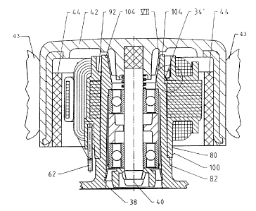
An improved external rotor motor, suitable for driving a cooling fan, has a structure which facilitates automated assembly with proper angular registration of its components. The motor has an external rotor (42) with a central shaft (40) which is rotatably supported inside a bearing support tube (38) having a tapered outer surface (98) formed with a circumferential stop (100) and a plurality of longitudinal guide grooves (102). An inner stator structure (22) is located radially between the bearing support tube (38) and the rotor (42). The inner stator has an internal recess (36) containing a securing ring or disk (20) with inwardly extending tabs (34). During assembly of the inner stator onto the bearing support tube (38), the tabs of the securing ring slide in the guide grooves (102), then bend to form barbs (34') which engage into the outer surface (98) of the bearing support tube, thereby securing the stator (22) on the bearing support tube in a precisely predefined angular orientation. The circumferential stop (100) assures insertion of the bearing support tube to the correct depth.


French Abstract

L'invention concerne un moteur de rotor externe amélioré, destiné à un ventilateur et comprenant une structure qui facilite l'assemblage automatisé avec un enregistrement angulaire approprié de ses composants. Le moteur comporte un rotor externe (42) muni d'un arbre central (40) qui est supporté par rotation à l'intérieur d'un tuyau de palier-support (38) ayant une surface externe tronconique (98) formée par un butoir circonférentiel (100) et une pluralité de rainures de guidage longitudinales (102). Une structure de stator interne (22) est située radialement entre le tuyau de palier-support (38) et le rotor (42). Le stator interne comporte un évidement intérieur (36) comportant un anneau ou un disque de fixation (20) pourvu de volet déployés vers l'intérieur (34). Durant l'assemblage du stator interne au tuyau de palier-support (38), les volets de l'anneau de fixation glissent dans les rainures de guidage (102), puis se plient pour former des barbelures (34') qui entrent en prise avec la surface externe (98) du tuyau de palier-support, fixant ainsi le stator (22) au tuyau de palier-support selon une orientation angulaire prédéfinie de manière précise. Le butoir circonférentiel (100) assure l'insertion du tuyau de palier-support à la bonne profondeur.

Claims

Note: Claims are shown in the official language in which they were submitted.


What is claimed is:

1. An external rotor motor, comprising:
an inner stator including a lamination stack having a
coating at least partially covering it, said inner stator
being formed with an internal recess;

an external rotor;

a bearing support tube having an inner side equipped
with a bearing arrangement for journaling said external
rotor, and having an outer side to which said inner stator
is secured;
an annular securing disk made of a ferromagnetic
material and secured in said coating of said lamination
stack, said disk being formed with projecting portions
extending radially inward, with respect to a central axis of
said bearing support tube into said internal recess of the
inner stator, said projecting portions having bent portions
which engage as barbs into said outer side of said bearing
support tube, and thereby prevent axial separation of said
stator from said bearing support tube; and

wherein said beating support tube has, on its exterior
surface, a plurality of axially extending longitudinal guide
grooves into which said projecting portions of said annular
securing disk engage, thereby defining and maintaining a
predetermined angular orientation between said bearing
support tube and said stator.

7


2. The external rotor motor of claim 1, wherein said
bearing support tube has a first end, dimensioned narrower
than a diameter of said stator internal recess and a second
end, dimensioned wider than said stator internal recess, and
wherein said bent portions of said securing disk are angled
diagonally toward said first end of said tube, thereby
preventing axial movement of said tube out of said stator
internal recess.

3. The external rotor motor of either one of claims 1 or 2,
wherein said annular securing disk is arranged adjacent to
said lamination stack of the inner stator.

4. The external rotor motor of any one of claims 1 to 3,
wherein an outer surface of said bearing support tube is
formed with a stop and, upon mounting of said inner stator
onto said tube, said stator abuts against said stop.

5. The external rotor motor of any one of claims 1 to 4,
wherein at least one of said extending portions has a width
which corresponds to a width of an associated one of said
guide grooves.

6. The external rotor motor of any one of claims 1 to 5,
further comprising fan blades formed on an outer periphery of
said external rotor.

8


7. The external rotor motor of any one of claims 1 to 6,
wherein said external rotor has a diameter not exceeding 60
mm.

8. A fan having, as its drive motor, an external rotor
motor comprising:

an inner stator including a lamination stack having a
coating at least partially covering it, said inner stator
being formed with an internal recess;

an external rotor;

a bearing support tube having an inner side equipped
with a bearing arrangement for rotatably supporting said
external rotor, and having an outer side to which said inner
stator is secured, said outer side bearing a plurality of
axially extending grooves;

an annular securing disk secured in said coating of said
lamination stack, said disk being formed with projecting
portions extending radially inward, with respect to a central
axis of said bearing support tube into said internal recess
of the inner stator, said portions simultaneously defining an
angular orientation of said stator with respect to said tube
and serving as barbs extending, in a mounted orientation,
both radially inward and away from said bearing arrangement,
and engaging into said outer side of said bearing support
tube to prevent axial separation of said stator from said
tube.

9

Description

Note: Descriptions are shown in the official language in which they were submitted.


CA 02454877 2003-12-30
EXTERNAL ROTOR MOTOR
Inventor: Francisco Rojo LULIC
FIELD OF THE INVENTION:
The present invention relates generally to an external
rotor motor, and more particularly to very small motors
typically used in cooling fans installed inside the housings
of personal computers.
BACKGROUND:
The assignee of the present invention, ebm-papst
St. Georgen GmbH & Co. KG (hereinafter simply "PAPST")
manufactures small motors which serve, for example, for
cooling of the processors in computers, for device cooling of
other small devices, etc. These motors have small dimensions.
For example:
fans of the PAPST Series 250 have dimension 8 x 25 x 25 mm;
fans of the PAPST Series 400F have dimensions 10 x 40 x 40 mm;
fans of the PAPST Series 400 have dimensions 20 x 40 x 40 mm;
fans of the PAPST Series f00 have dimensions 25.4 x ~0 x 60
mm. The power consumption of such fans falls in the range
from 0.4 to 0.6 watts for the Series 250, 0.7 to 0.9 watts for
the Series 400F, and 0.9 to 1.6 watts for the Series 400 and
600.
External rotor motors in the form of small or miniature
motors are often used to drive fans, e.g. those in computers
for cooling of the processors. The components of such motors
are so small that they look like toys or parts of watches.
This is necessary, in order that such motors can, despite
their smallness, be assembled simply, with high precision, and
economically, preferably by means of an automated assembly
process.
SUMMARY OF THE INVENTION:
It is therefore an object of the invention to provide a
new external rotor motor, wherein the inner stator is
supported on a bearing support tube for the shaft of the
external rotor, and there is an annular securing ring or disk
1

CA 02454877 2003-12-30
which secures the bearing support tube and inner stator
together. The invention is particularly adapted for use in
motors whose rotors are less than about 60 mm in diameter.
The fact that one or more portions of the annular
securing disk extend radially into the internal recess of the
inner stator, bend themselves during the assembly process, and
engage as barbs into the outer surface of the bearing support
tube, assures that, when the inner stator and bearing support
tube are assembled, trey engage securely. The securing
disk portions serve as barbs or claws. In case an impact load
is placed on the junction of these elements, the barbs dig
themselves deeper into the material of the bearing support
tube, generally a plastic or an aluminum alloy, so that a
secure fastening is created, which as a practical matter can
no longer be disassembled. By this means, assembly is
simplified, can be done quickly and automatically, and results
in a product with the necessary high precision.
The form of the securing disk can vary. It can have one
or multiple claws of varying forms, the optimal form being
dependent upon the nature of the intended application.
BRIEF FIGURE DESCRIPTION:
Further details and advantageous refinements of the
invention will be apparent from the following description and
drawings of preferred embodiments, which are intended as
exemplary only, not as any limitation of the invention.
FIG. 1 is a plan view of a preferred form of an annular
securing disk, as can be used in the present invention;
FIG. 2 is a longitudinal section through the stator of an
external rotor motor, having an annular securing disk
according to FIG. l, looking along line II-II of FIG. 3;
FIG. 3 is a plan view of the stator of FIG. 2, looking in
the direction of arrow III of FIG. 2;
FIG. 4 shows the inner stator of FIGS. 2 & 3, but in a
section longitudinally along line IV-IV of FIG. 3, and at the
beginning of the mounting of the inner stator onto a bearing
support tube;
FIG. 5 is an enlarged view of detail V of FIG. 4;
2

CA 02454877 2003-12-30
FIG. 6 is a view like that of FIG. 4, in which the inner
stator, in which the inner stator is in its final position
mounted on the bearing support tube, and also showing the
external rotor; and
FIG. 7 is an enlarged view of detail VII of FIG. 6.
DETAILED DESCRIPTION:
FIG. 1 illustrates a securing ring or disk 20,
as used in the present invention for an internal stator 22
(FIGS. 2 & 3) with a lamination stack 23 having four radially
extending poles 24, 26, 28, 30. To match these four stator
poles, the securing ring has four radially outwardly extending
projections 32 and four radially inwardly extending tabs 34.
Two poles 38, 30 of lamination stack 23 are shown in FIG. 1.
Securing ring 20 preferably comprises ferromagnetic material.
Lamination stack 23 is formed with an internal recess 36
which can be assembled onto a bearing support tube 38, as may
be seen by comparing FIG. 4 (partial insertion) with FIG. 6
(full insertion). As shown in FIG. 6, inside the bearing
support tube 38, there is supported, on bearings, the central
shaft 40 of an external rotor 42 which has permanent magnets
44, which interact in the conventional manner with poles 24
through 30 of inner stator 22. This journalling keeps rotor
42 properly aligned with respect to stator 22.
Usually, these motors are electronically commutated, e.g.
with the help of a rotary position sensor or a sensor coil.
The mode of operation of such motor's, which have been made in
quantities of millions of units, is familiar to those skilled
in the art, and therefore need not be described here. On the
outer surface of rotor 42, fan blades or vanes 43 are
preferably provided, and may be integrally formed with the
external rotor; see FIG. 6.
As FIG. 2 shows, securing ring or disk 20 is preferably
placed on the upper end of lamination stack 23 so that its
inner diameter or periphery 48 is substantially aligned with
the inner diameter 36 of lamination stack 23 and the tabs 34
extend into the inner recess 36, as best seen in FIGS. 3,
& 7. In one exemplary motor, the outer diameter of the
8703-166 (RfR 292f 3 2 DEC. 2003

CA 02454877 2003-12-30
lamination stack 23 was about 22 mm and the diameter of recess
36 was about 10 mm.
Between stator poles 24-30 are located stator slots 50,
52, 54, 56, in which a winding with two phases 58, 60 is
wound, whose winding direction and circuit configuration are
clearly apparent from FIG. 3 for this exemplary embodiment.
The winding ends are connected with three terminals 62, 64, 66
in such a manner that one end of both phases 58, 60 is
connected to terminal 64, the other end of phase 60 is
connected to terminal 62, and the other end of phase 58 is
connected to terminal 66.
In the region of slots 50 to 56, the outer diameter 70 of
securing ring 20 preferably matches the adjacent outer
diameter 72 (FIG. 1) of lamination stack 23, while in the
region of poles 24-30, the radial projections 32 are located,
and therefore extend into these poles, improving the cross
section of the magnetic circuit in stator 22 and thereby
improving the efficiency of the motor.
Lamination stack 23 is surrounded by an insulating
coating or covering 76, which also insulates slots 50-56 and
thereby serves as a coil former for the winding phases 58, 60.
This coating 76 also secures the terminals 62, 64, 66 in an
insulated manner with respect to inner stator 22, and it
secures securing ring 20 onto the upper end of lamination
stack 23; cf. FIG. 2.
Further, coating 76 forms, at the upper end (referring to
FIG. 2) of stator 22, a tube-shaped extension 80 with a lower
rim 82 whose inner diameter 84 is substantially the same
diameter as that of recess 36 of lamination stack 23.
Toward its top, referring to FIG. 2, coating 76 tapers
down in its segments 86, 88, 90, 92 (FIG. 3) which, seen in
the circumferential direction, are located in respective gaps
between tabs 34 of securing ring 20. Further, there extends
upward a collar 94, which is a part of the coil former for the
phases 58, 60. Phases 58, 60 preferably are so-called
bifilary or double-wound windings, i.e. wires 58 and 50 are
wound parallel.
8703-166 (R+R 282) 4 2 DEC. 2003

CA 02454877 2003-12-30
As shown in FIG. 4, bearing support tube 38 has a
frusto-conical circumferential surface 98 which extends
downwardly to a shoulder 100. In the upper portion of this
circumferential surface 98, there are formed, at respective
intervals of about 90 degrees, four longitudinal slots 102
whose spacing from a central axis 101 increases from the top
toward the bottom. These longitudinal slots serve (as shown
in FIG. 7) for longitudinal guidance of the inward tabs 34 of
securing ring 20 and for radial securing, since their width
substantially corresponds to the widths of tabs 34 (FIG. 1 and
FIG. 3), so that the circumferential or angular orientation of
stator 22, relative to bearing support tube 38, is precisely
defined. This is important because the rotor position sensor
(not shown) of the motor is secured to bearing support tube 38
and must have a predetermined angular orientation relative to
stator 22.
As shown in FIG. 4, stator 22 is placed, in this correct
angular position, onto bearing support tube 38 and is pressed
downward with a pressure P. The tubular part 80 is pressed so
far onto the outer circumference 98 of bearing support tube 38
that the lower end 82 of part 80 engages against shoulder 100.
In this manner, as indicated in FIGS. 4 and 5, the inward
tabs 34 of securing ring 20 impact against the upper end 104
(cf. FIGS. 5 & 6) of bearing support tube 38 and thereby are
bent upward, as shown in FIGS. 6 & 7, to form barbs 34'.
FIG. 7 shows such a tab in its bent state 34' in which it is
so locked into the associated longitudinal slot 102, that
disassembly is, for practical purposes, no longer possible.
Any force tending to pull bearing support tube 38 back out of
recess 36 of stator 22 would only dig barbs 34° deeper into
outer surface 98 of tube 38.
Simultaneously, segments 86, 88, 90 and 92 engage
elastically against the outer circumferential surface 98 of
bearing support tube 38 and provide additional centering and
securing, in order to avoid any possible unsymmetrical
assembly of stator 22 onto bearing support tube 38.
One thereby achieves a simple and absolutely secure
8703-166 (RJR 2821 5 2 DEC. 2003

T
CA 02454877 2003-12-30
assembly, of stator 22 on the bearing support tube 38, that is
very well adapted for automated production, even when the
motor has very small dimensions.
Naturally, within the scope of the inventive concept,
many variations and modifications are possible. In
particular, employing the teaching of the invention can also
be very advantageous in the case of larger external rotor
motors.
803-166 (RsR 282) 6 2 DEC. 2003

Representative Drawing
A single figure which represents the drawing illustrating the invention.
Administrative Status

For a clearer understanding of the status of the application/patent presented on this page, the site Disclaimer , as well as the definitions for Patent , Administrative Status , Maintenance Fee  and Payment History  should be consulted.

Administrative Status

Title Date
Forecasted Issue Date 2010-02-09
(22) Filed 2003-12-30
(41) Open to Public Inspection 2004-07-23
Examination Requested 2008-07-17
(45) Issued 2010-02-09
Expired 2024-01-02

Abandonment History

There is no abandonment history.

Payment History

Fee Type Anniversary Year Due Date Amount Paid Paid Date
Registration of a document - section 124 $100.00 2003-12-30
Application Fee $300.00 2003-12-30
Maintenance Fee - Application - New Act 2 2005-12-30 $100.00 2005-10-24
Maintenance Fee - Application - New Act 3 2007-01-01 $100.00 2006-11-01
Maintenance Fee - Application - New Act 4 2007-12-31 $100.00 2007-11-01
Request for Examination $800.00 2008-07-17
Maintenance Fee - Application - New Act 5 2008-12-30 $200.00 2008-10-22
Maintenance Fee - Application - New Act 6 2009-12-30 $200.00 2009-11-02
Final Fee $300.00 2009-11-30
Maintenance Fee - Patent - New Act 7 2010-12-30 $200.00 2010-11-08
Maintenance Fee - Patent - New Act 8 2011-12-30 $200.00 2011-11-10
Maintenance Fee - Patent - New Act 9 2012-12-31 $200.00 2012-10-23
Maintenance Fee - Patent - New Act 10 2013-12-30 $250.00 2013-11-04
Maintenance Fee - Patent - New Act 11 2014-12-30 $250.00 2014-11-28
Maintenance Fee - Patent - New Act 12 2015-12-30 $250.00 2015-11-25
Maintenance Fee - Patent - New Act 13 2016-12-30 $250.00 2016-11-22
Maintenance Fee - Patent - New Act 14 2018-01-02 $250.00 2017-11-23
Maintenance Fee - Patent - New Act 15 2018-12-31 $450.00 2018-10-30
Maintenance Fee - Patent - New Act 16 2019-12-30 $450.00 2019-12-16
Maintenance Fee - Patent - New Act 17 2020-12-30 $450.00 2020-12-22
Maintenance Fee - Patent - New Act 18 2021-12-30 $459.00 2021-12-20
Maintenance Fee - Patent - New Act 19 2022-12-30 $458.08 2022-12-15
Owners on Record

Note: Records showing the ownership history in alphabetical order.

Current Owners on Record
EBM-PAPST ST. GEORGEN GMBH & CO. KG
Past Owners on Record
LULIC, FRANCISCO ROJO
Past Owners that do not appear in the "Owners on Record" listing will appear in other documentation within the application.
Documents

To view selected files, please enter reCAPTCHA code :


To view images, click a link in the Document Description column. To download the documents, select one or more checkboxes in the first column and then click the "Download Selected in PDF format (Zip Archive)" or the "Download Selected as Single PDF" button.

List of published and non-published patent-specific documents on the CPD .

If you have any difficulty accessing content, you can call the Client Service Centre at 1-866-997-1936 or send them an e-mail at CIPO Client Service Centre.


Document
Description 
Date
(yyyy-mm-dd) 
Number of pages   Size of Image (KB) 
Abstract 2003-12-30 1 33
Description 2003-12-30 6 288
Claims 2003-12-30 2 86
Drawings 2003-12-30 7 167
Representative Drawing 2004-04-19 1 26
Cover Page 2004-06-28 1 60
Claims 2008-07-18 3 91
Cover Page 2010-01-19 2 69
Assignment 2003-12-30 4 161
Fees 2005-10-24 1 32
Fees 2006-11-01 1 38
Fees 2007-11-01 1 43
Prosecution-Amendment 2008-07-17 2 49
Prosecution-Amendment 2008-07-18 4 125
Fees 2008-10-22 1 40
Fees 2009-11-02 1 41
Correspondence 2009-11-30 2 48
Fees 2010-11-08 1 36