Note: Descriptions are shown in the official language in which they were submitted.
CA 02454884 2004-01-06
3105 0039
METHOD OF FUSING AND STRETCHING
A LARGE DIAMETER OPTICAL WAVEGUIDE
BACKGROUND OF THE INVENTION
Field of the Invention
The invention generally relates to fabricating a large diameter optical
waveguide preform. More particularly, the invention relates to overcladding a
preform for use in making a large diameter optical waveguide such as a cane
waveguide.
Description of the Related Art
An optical fiber is generally fusion drawn from a fiber preform by one of
several processes. The fiber preform is essentially an undrawn optical fiber
that is
an enlarged embryonic version of the optical fiber. The fiber preform includes
a core
and a cladding in the same ratio as desired for the optical fiber that is to
be fusion
drawn from the fiber preform. In one example, a 1 meter long fiber preform
with an
outer diameter of 3 centimeters can be fusion drawn to produce an
approximately 90
kilometer long optical fiber with an outer diameter of 125 microns.
Preforms are traditionally manufactured by chemical vapor deposition
(CVD), which may include modified chemical vapor deposition (MCVD), plasma
modified chemical vapor deposition (PMCVD or PCVD), outside vapor deposition
(OVD), and vapor axial deposition (VAD). In MCVD, glass forming oxides deposit
on
the inside of a silica tube using a heat source such as an oxygen/hydrogen
(02/H2)
torch or a plasma torch to drive the oxidation reaction. In OVD and VAD, glass
forming oxides deposit on a target mandrel and far greater deposition rates
can be
achieved. The low deposition rates in MCVD are offset by the ability to
fabricate
complex waveguide profiles. The preform resulting from one of the CVD
processes
before adding additional layers of cladding is called a seed preform.
As a consequence of the low deposition rates and process set up times,
preforms made by MCVD often require additional silica layers added to the
outside
of the seed preform to achieve the desired doped glass core to outside
diameter
ratio. Often, the additional layers are added to the seed preform by inserting
the
seed preform into a silica sleeve or tube and fusing the sleeved seed preform
on the
1
CA 02454884 2007-01-09
3105 0039
same lathe with the same or a similar 02/H2 torch as used during the
deposition of
the seed preform. Alternatively, U.S. Patent No. 5,578,106 discloses replacing
the
02/H2 torch with a plasma torch for the heat source. Additionally, U.S. Patent
Nos.
4,820,322 and 6,053,013 disclose inserting a preform into a sleeve or tube of
cladding material and fusing this one additional layer on a fiber optic draw
tower in
order to permit fusing while simultaneously stretching the fiber and fused
material to
a desired final diameter. However, all of the methods disclosed in these
patents are
methods for sleeving and fusing seed preforms during the drawing of an optical
fiber.
The fiber preform that is created and used to draw the optical fiber in the
prior art has
undergone at most a single sleeve and fusing operation. However, the
production of
the optical fiber may require multiple sleeving and stretching steps prior to
the final
draw of the optical fiber.
Large diameter optical waveguides called cane waveguides, such as
described in U.S. Patent No. 6,982,996, issued January 3, 2006, are rigid
structures
unlike optical fibers and have a core similar in size to that of a
conventional optical
fiber. However, the cane waveguides have a much larger cladding than the
optical
fiber. Thus, a cane preform requires substantially more cladding relative to
the core
than the fiber preform for the optical fiber. The core in a cane waveguide for
a single
mode of transmission is approximately 4 to 9 microns in diameter while the
core for
multi-mode transmission is approximately 50 to 60 microns in diameter. Unlike
the
125 micron outer diameter of the optical fiber, the outer diameter of the cane
waveguide is approximately 1 to 10 mm for either single mode or multi-mode
transmission. Additionally, a cane preform has an outer diameter in the range
of
from approximately 5 to 100 mm.
Fabricating the cane preform requires fusing multiple sleeves to the seed
preform since a single sleeve and fusing operation as used in the preparation
of a
fiber preform fails to provide a sufficient thickness of cladding needed for a
cane
preform when starting with the seed preform. However, the prior art does not
address the problem of how to perform multiple fusing operations to add
multiple
sleeves. For example, U.S. Patent Nos. 4,820,322 and 6,053,013 provide for a
2
CA 02454884 2004-01-06
3105 0039
single fusing operation to produce a fiber preform from a seed preform from
which an
optical fiber is drawn. Performing a series of fusing operations to add
multiple
sleeves by using a lathe and the same or similar 02/H2 torch as used in
fabricating
the seed preform by CVD decreases product yield since this process is slow.
Therefore, there exists a need for methods to more rapidly perform
multiple sleeving and fusing operations necessary during the production of
optical
waveguides.
SUMMARY OF THE INVENTION
The invention generally relates to methods for making a preform for a
large diameter optical waveguide such as a cane waveguide. The method includes
inserting a preform into a glass tube to serve as cladding that provides a
thickened
preform, simultaneously fusing and stretching the thickened preform,
sectioning the
stretched and thickened preform and repeating the procedure as necessary to
provide an even further thickened preform. The drawing apparatus can be
configured to work with the preform disposed either horizontally or vertically
and
usually includes a graphite resistance furnace. Typically, the drawing
apparatus is
an upper portion of a draw tower used for drawing an optical fiber from an
optical
fiber preform. The draw tower includes a tractor pulling mechanism that can
adjust
to grip a wide range of diameters.
BRIEF DESCRIPTION OF THE DRAWINGS
So that the manner in which the above recited features of the present
invention can be understood in detail, a more particular description of the
invention,
briefly summarized above, may be had by reference to embodiments, some of
which
are illustrated in the appended drawings. It is to be noted, however, that the
appended drawings illustrate only typical embodiments of this invention and
are
therefore not to be considered limiting of its scope, for the invention may
admit to
other equally effective embodiments.
Figure 1 is a view illustrating the operation of making a cane preform using
a draw tower.
Figure 2 is a top cross sectional view of a seed preform inside a sleeve.
3
CA 02454884 2004-01-06
3105 0039
Figure 3 is a sectional view of the seed preform inside the sleeve that is
taken across Line 3-3 of Figure 2.
Figure 4 is a flowchart illustrating a method for making the cane preform.
DETAILED DESCRIPTION OF THE PREFERRED EMBODIMENT
The invention provides a method for fabricating a large diameter optical
waveguide such as a cane waveguide, which can be fabricated from a cane
preform.
The large diameter waveguide is photosensitive and guides propagating light,
e.g., a
germania-doped silica core fiber having an outer cladding diameter of
approximately
1-10 millimeters and a core outer diameter of about 4-60 micrometers depending
on
whether the waveguide is single mode or multi-mode. As such, the large
diameter
waveguide has a larger cladding to core ratio than an optical fiber that
typically has
an outer cladding diameter of approximately 125 micrometers and a core
diameter of
approximately 9 micrometers. The optical waveguide may be made from other
materials or glasses, e.g., silica, phosphate glass, glass and plastic, or
solely plastic.
Also, a multi-mode, birefringent, polarization maintaining, polarizing, multi-
core, flat
or planar (where the waveguide is rectangular shaped), or other optical
waveguide
may be used if desired.
Figure 1 illustrates a drawing apparatus 100 in use during one of a series
of steps for simultaneously fusing and stretching a preform such as a seed
preform
158 in the first stage and then a cane preform in later stages. Use of the
drawing
apparatus 100 does not require a separate overcladding process such as a
fusing
operation separate and distinct from stretching or drawing a sleeved and fused
assembly. The drawing apparatus 100 may be the upper portion of a draw tower
used for drawing an optical fiber from an optical fiber preform that has been
modified
to include a tractor pulling mechanism 170 able to grip a wide range of
diameters.
The tractor pulling mechanism 170 adjusts to grip lengths of preform having
various
thicknesses that range from the size of a leading strand from the seed preform
which
is typically on the order of a few hundred microns in diameter to the size of
the cane
preform which is typically from 2 to 10 mm in diameter. The drawing apparatus
100
may also be as shown but configured to draw a preform 158 disposed such that
the
long axis of the preform 158 is horizontal.
4
CA 02454884 2004-01-06
3105 0039
Referring now also to Figures 2 and 3, a seed preform 158 having a core
158a and a first layer of cladding 158b is inserted into a glass tube 156
during use of
the drawing apparatus 100. In this manner, the seed preform 158 is sleeved to
provide a preform/ tube assembly 155. Preparatory to fusing and stretching the
preform/ tube assembly 155 with the drawing apparatus 100, one end 155a of the
preform/ tube assembly 155 is sealed together leaving the other end 155b
unsealed.
Alternatively, one end of the tube 156 can be sealed without necessarily
fusing to the
seed preform 158 (i.e. the bottom of the tube 156 is sealed with the seed
preform
158 suspended above the sealed portion of the tube 156). The unsealed end 155b
clamps in a chuck 154 connected to a vacuum pump 152 and provided with a feed
module 150 of the drawing apparatus 100. Throughout the operation of the
drawing
apparatus 100, the vacuum pump 152 removes air from the annular gap 157
between the preform 158 and the glass tube 156. The vacuum pump 152 maintains
a vacuum of approximately -700 mm of mercury in the gap 157.
The sealed end 155a feeds into a graphite resistance furnace 162 and
aligns with a hot zone of the furnace 162. The graphite resistance furnace 162
includes a tubular structure having sides made of graphite through which
direct
current flows and causes heat via Joulean heating. Other types of furnaces or
heat
sources such as an induction heater or an open flame may be used instead of
the
graphite resistance furnace 162. However, the graphite resistance furnace 162
is
preferable since the furnace 162 provides good control of the heat zone in
both
spatial extent and in temperature and is able to turn on and off as needed. In
operation, argon (Ar) gas or some other inert gas or combination of inert
gases is
injected at about 10 liters per minute (LPM) into the bore of the graphite
resistance
furnace 162 to prevent oxidation of the graphite. The sealed end 155a of the
preform/ tube assembly 155 may be preheated by the furnace 162 for
approximately
twenty minutes, depending on the operating parameters. Further heating softens
the
preform/ tube assembly 155 until a leading strand (not shown) from the sealed
end
155a drops down if the long axis of the preform 158 is oriented vertically in
the
drawing apparatus 100 or is pulled if the preform 158 is oriented
horizontally.
The tractor pulling mechanism 170 grips the leading strand when the
strand drops down to the tractor pulling mechanism 170. The tractor pulling
5
CA 02454884 2004-01-06
3105 0039
mechanism 170 may be disposed downstream of the graphite resistance furnace
162 and close enough to the furnace that the tractor pulling mechanism 170
grips the
stretched and thickened preform 160 being extruded from the furnace instead of
the
leading strand. When the stretched and thickened preform 160 is completely
extruded from the furnace 162, the leading strand is cut off and discarded.
Once in
the grip of the tractor pulling mechanism 170, the strand is pulled at the
same time
as the preform 158 feeds into the graphite resistance furnace 162 by the feed
module 150. In this manner, a stretched preform 160 extrudes from or is drawn
from
the furnace 162. The glass tube 156 fuses to the preform 158 as the preform/
tube
assembly 155 passes through the furnace 162. The stretched preform 160 has a
predetermined thickness and a predetermined cladding to core ratio. However,
the
stretched preform 160 is an intermediate stage cane preform that may be too
thin
and lacks the proper cladding to core ratio to be used for a cane preform.
The intermediate stage cane preform may be sectioned (e.g. cut into three
sections) and each section inserted into a second glass tube to provide a
thicker
preform/ tube assembly that is mounted in the drawing apparatus 100 in the
same
manner as the preform/ tube assembly 155 having the seed preform 158 therein.
Sectioning the intermediate stage cane preform provides for manageable lengths
of
the intermediate stage cane preform. The process for using the drawing
apparatus
100 as described above is repeated to provide subsequent intermediate stage
cane
preforms, and, eventually the final cane preform or the final cane waveguide.
The
actual outer diameter of the thicker preform/ tube assembly may not be larger
than
the preform/ tube assembly 155 having the seed preform 158 therein so long as
the
proper cladding to core ratio is achieved with the proper outer diameter of
the final
cane preform or the final cane waveguide. Thus, the thicker preform/ tube
assembly
merely refers to a larger cladding to core ratio than the preform/ tube
assembly 155
having the seed preform 158 therein. The tractor pulling mechanism 170 may be
adjusted between each subsequent sleeving, fusing, and stretching to
accommodate
any increases in the outer diameters of respective products, i.e. subsequent
intermediate stage cane preforms or the final cane preform. The entire process
as
described is typically repeated two times to make the final cane preform and
three
times to make the final cane waveguide.
6
CA 02454884 2004-01-06
3105 0039
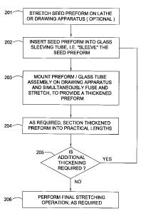
Figure 4 shows a flowchart summarizing a particular method for fabricating
the cane preform or the cane waveguide using the drawing apparatus 100 as
described in detail above and shown in Figure 1. The flowchart includes a
first step
201 in which a seed cane preform having a core sized to end with a final
diameter
appropriate for single-mode or multi-mode transmission and an outer diameter
of
approximately 5 mm is optionally stretched on a lathe or drawing apparatus to
arrive
at a desired starting cladding to core ratio and provide a small enough outer
diameter to fit inside a glass tube. For this particular embodiment, the glass
tube
has an inner diameter of approximately 10 mm and an outer diameter of
approximately 30 mm. In a next step 202, the seed cane preform is placed into
the
glass tube such that the seed cane preform is sleeved. In a further step 203,
the
combined preform/ tube assembly is simultaneously fused and stretched using
the
drawing apparatus to provide a thickened preform (e.g. an intermediate stage
cane
preform). As described above, the thickened preform has a larger cladding to
core
ratio but may not have a greater overall diameter due to the stretching. The
thickened preform is then sectioned into practical lengths in a step 204.
As indicated at step 205, steps 202 through 204 are repeated until a
desired final cane preform with an outer diameter of approximately 5 mm and a
desired cladding to core ratio is achieved. In a final step 206, the cane
preform may
be further drawn on the drawing apparatus using a precision tractor pulling
mechanism if the cane preform does not already have the desired final cladding
to
core ratio. Thus, at least two sleeves are used and at least two simultaneous
fusing
and stretching operations are performed in producing the cane preform from the
seed cane preform. To produce a cane waveguide from the cane preform, an
additional sleeving operation followed by a simultaneous fusing and stretching
operation is performed.
The stretching shown in the steps 201, 203 or 206 may alternatively be
used to pre-draw a finished preform to a smaller diameter prior to a final
draw.
Some fiber coating processes used to apply coatings such as polyimide or
carbon
require slow draw speeds to deposit the desired thickness. The slow draw speed
coupled with a high preform to fiber or waveguide size ratio results in poor
control of
the diameter of the fiber or waveguide. Further, slow draw speeds are
difficult to
7
CA 02454884 2004-01-06
3105 0039
achieve with large diameter preforms (e.g. larger than 30 mm) because of
instabilities of the draw furnace thermal gradient and the feed module. Thus,
the
stretching operation in the steps 201, 203 or 206 allows coating processes
completed later to be performed slowly since the preform may be substantially
pre-
drawn during the steps 201, 203 or 206.
Embodiments of the invention provide many advantages when compared
to traditional methods that do not provide multiple simultaneous fusing and
stretching
of preforms. One advantage is that a small inner diameter draw furnace can be
used
to provide high yields of waveguide per seed preform. A seed preform may
require
an overclad of 200 mm in diameter or greater in order to have a cladding to
core
ratio needed for a waveguide with single mode operation. Thus, the preform/
tube
assembly used in a single sleeving and fusing operation requires such a large
sleeve
tube that a larger inner diameter draw furnace than is commercially available
today is
required. The multiple simultaneous fusing and stretching process reduces the
size
of the preform/ tube assemblies since each fusing and stretching operation
changes
the cladding to core ratio without necessarily increasing the overall outer
diameter.
Another advantage is that larger core diameters can be deposited in the
seed preform due to the multiple stretchings that achieve the proper cladding
to core
ratio. Typically, an MCVD process results in a core varying along the length
of the
seed preform. However, multiple core deposition passes effectively average the
variations from each deposition layer along the core in order to minimize the
overall
variability. The ability to use larger core diameters permits the multiple
core
deposition passes.
Still another advantage is that precise sizing of cladding to core ratio is
possible, which reduces variability in the cladding to core ratio and reduces
the raw
material inventory. Since the seed preform is optionally stretched or drawn
prior to
sleeving, the seed preform core diameter can be predetermined to mate with a
fixed
sleeve tube cross sectional area. In other words, variability in cladding to
core ratio
among different seed preforms can be adjusted during the seed preform stretch
phase to yield a precise cladding to core ratio when sleeved and fused with a
given
tube during final or intermediate draws. This allows for tighter core
diameter, second
mode cutoff and mode field diameter tolerances in the cane preform or cane
8
CA 02454884 2004-01-06
3105 0039
waveguide. The less forgiving prior art single sleeving and fusing operation
followed
by a stretching operation requires very tight seed preform manufacture process
control and/or multiple sleeve tube CSA availability. Even with lathe preform
stretching techniques, the seed preform cannot be stretched uniformly because
of
extra variables such as flame uniformity, preform sagging on horizontal
lathes, and
glass burn off from flame heating.
Yet another advantage is reduced final waveguide hydroxyl ion (OH)
concentration when compared to that resulting from sleeving and 02/H2 torch
stretching. Traditional lathe sleeving and fusing techniques that collapse a
sleeve
tube over a seed preform can lead to migration of OH and hydrogen (H2) in the
core
and inner cladding of the preform and the subsequently drawn cane preform or
cane
waveguide. The OH and H2 contamination results in significant optical
attenuation,
particularly in the 1350 nm to 1450 nm wavelength range.
Yet even another advantage is the higher final waveguide yield compared
to torch driven fusing and stretching. The invention reduces burn off and tip-
off loss,
i.e. loss of material at the tip of the preform during the overcladding
process because
the material is of the wrong diameter. Preform sleeving and fusing using a gas
burner as the heat source results in removal of 20% to 25% of the silica
material due
to the intense heat and reducing atmosphere. However, adjusting gas flows of
the
burner to reduce burn off results in a cooler flame that greatly increases
process time
and may make sleeving impossible. The sleeving and then simultaneous fusing
and
stretching with the draw tower and furnace in accordance with embodiments of
the
invention results in little or no burn off because the process takes place in
an inert
atmosphere.
Still yet even another advantage is increased throughput. To sleeve and
fuse a preform and then stretch it on a lathe takes about two to three hours.
However, the sleeving and then simultaneous fusing and stretching process when
performed on the draw tower according to the invention requires less than one
hour.
Even yet another advantage is the uniform outer diameter provided by the
invention using the drawing apparatus. Preforms stretched on a lathe using a
gas
burner result in diameter variations on the order of 100 microns. The graphite
9
CA 02454884 2004-01-06
3105 0039
resistance furnace provides better temperature control compared to an 02/H2
gas
burner as typically used with the lathe. The superior temperature control
results in a
uniform melt and stretch that provides a final outer diameter that varies on
the order
of only 10 microns or less.
Yet another advantage is that the invention allows continuous preform
stretch for large glass lot sizes. Preforms stretched using a lathe are
limited in final
length by the size of the lathe bed. If longer stretching is required, the
process must
be stopped to section cut the stretched preform and axially reposition the
lathe
chucks. With the invention, the tractor pulling mechanism pulls the stretched
preform continuously such that the preform can be sectioned at any point after
the
tractor pulling mechanism or left in one piece.
It is to be understood that the above described arrangements are only
illustrative of the application of the principles of the invention. In
particular, it should
be understood that although the invention has been shown and described for
making
a cane preform, the invention may be used in making a preform for any optical
waveguide in which the cladding is substantially greater in thickness than for
an
optical fiber. In this manner, multiple sleeving and then simultaneous fusing
and
stretching operations would be either required or advantageous. More
generally, the
invention may be used to advantage when producing any type of optical
waveguide
or optical fiber prior to the final draw.
While the foregoing is directed to embodiments of the present invention,
other and further embodiments of the invention may be devised without
departing
from the basic scope thereof, and the scope thereof is determined by the
claims that
follow.