Note: Descriptions are shown in the official language in which they were submitted.
CA 02454896 2004-O1-05
1
METHOD OF PRODUCING OPTICAL FIBER PREFORM, AND
OPTICAL FIBER PREFORM AND OPTICAL FIBER PRODUCED WITH THE
METHOD
BACKGROUND OF THE INVENTION
Field of the Invention
The present invention relates to a method of producing an optical fiber pre-
form with the collapsing process and to an optical fiber preform and an
optical
fiber produced with the method.
Description of the Background Art
The collapsing process is a process to produce an optical fiber preform by
collapsing a glass pipe to form a solid body. The collapsing operation may be
performed with a glass rod inserted into a glass pipe. In this case, the glass
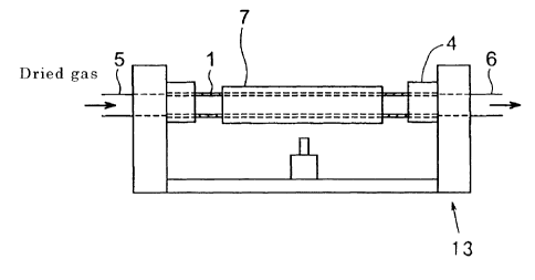
pipe and the glass rod are unified. Figure 17 is a schematic diagram showing
the collapsing process. A glass rod 2 is inserted in a glass pipe 1. The glass
pipe 1 is held by holding portions 4 of a glass-processing lathe 13. While the
glass pipe 1 is rotated together with the glass rod 2, one end of the glass
pipe is
sealed by heating it with a heat source 3. Then, the heat source 3 is moved to
collapse the glass pipe by heating it. The following techniques are also
known:
(a) Before the collapsing operation, the surface of the glass is chemically
puri-
feed by heating the glass pipe 1 while a chlorine gas is blown into it. (b)
The
collapsing operation is performed while the inside of the glass pipe 1 is
evacu-
CA 02454896 2004-O1-05
2
ated with a vacuum pump. (See the published Japanese patent application
Tokukaihei 8-225335.)
Phenomena of occlusion of water into silica glass and its release are ex-
plained in a reference book entitled "Application handbook for amorphous
silica
materials" (compiled by I~atsuro Fukamizu, published by Realize Co., 1999, pp.
56-57). Phenomena of diffusion of water into silica glass are explained in a
report by Hajimu Wakabayashi and Minoru Tomozawa, "Diffusion of water into
silica glass at low temperature" (J. Am. Ceram. Soc., Vol. 72, No. 10, pp.
1850-55, 1989).
Figure 18 is a graph showing an increment in transmission loss at a 1.4- ~r.L
m
wavelength band due to OH groups. OH groups in silica glass have a high ab-
sorption peak (OH absorption) in the vicinity of 1.4 ~.m in wavelength. The
OH absorption increases the transmission loss at a 1.4-pm band (OH-
originated loss) and makes it difficult to transmit signals in the 1.4-~m band
and excitation light fox Raman amplification. Therefore, it is desirable to
minimize the OH absorption. However, when an optical fiber preform is pro-
duced with the collapsing process, it has been difficult to reduce the OH
absorp-
tion_
SUMMARY OF THE INVENTION
An object of the present invention is to offer a method of producing with
the collapsing process an optical fiber preform capable of forming an optical
fiber in which an increment in transmission loss due to the OH absorption is
CA 02454896 2004-O1-05
3
reduced and to offer an optical fiber preform and an optical fiber produced
with
the method.
According to the present invention, the foregoing object is attained by offer-
ing the following method of producing an optical fiber preform. The method
comprises:
(a) a drying step to reduce the amount of hydrogen atom-containing sub-
stances in a glass pipe;
(b) a sealing step to seal one end of the glass pipe; and
(c) a collapsing step to collapse the glass pipe to obtain a solid body.
According to one aspect of the present invention, the present invention offers
the following method of producing an optical fiber preform. The method com-
prises:
(a) a drying step to heat a glass pipe at a temperature of 550 ~ or below;
(b) a sealing step to seal one end of the glass pipe; and
(c) a collapsing step to collapse the glass pipe to obtain a solid body
According to another aspect of the present invention, the present invention
offers an optical fiber preform produced through the following steps:
(a) heating a glass pipe at a temperature of 550 ~ or below;
(b) sealing one end of the glass pipe; and
(c) collapsing the glass pipe to obtain a solid body
The optical fiber preform's portion formed by the interface portion at the
time
of the collapsing contains OH groups at a concentration of 100 wt. ppb or
below.
According to yet another aspect of the present invention, the present inven-
CA 02454896 2004-O1-05
4
tion offers an optical fiber produced by drawing an optical fiber preform pro-
duced through the following steps:
(a) heating a glass pipe at a temperature of 550 ~ or below;
(b) sealing one end of the glass pipe; and
(c) collapsing the glass pipe to obtain a solid body.
The optical fiber has an OH-originated loss of less than 0.5 dB/km at a wave-
length of 1.38 a m.
In this specification, the optical fiber preform may be a glass body from
which
an optical fiber can be formed by directly drawing the glass body. The optical
fiber preform may also be a glass body (an intermediate of an optical fiber
pre-
form) to be further processed for the subsequent drawing.
Advantages of the present invention will become apparent from the following
detailed description, which illustrates the best mode contemplated to carry
out
the invention. The invention can also be carried out by different embodiments,
and their details can be modified in various respects, all without departing
from the invention. Accordingly, the accompanying drawing and the following
description are illustrative in nature, not restrictive.
BRIEF DESCRIPTION OF THE DRAWING
The present invention is illustrated to show examples, not to show limita-
tions, in the figures of the accompanying drawing. In the drawing, the same
reference numerals refer to similar elements.
CA 02454896 2004-O1-05
In the drawing:
Figures 1A and 1B are schematic diagrams showing the "blowing-away
purging," one of the embodiments of the drying step of the present invention,
in
which Fig. 1A shows the diagram when only a glass pipe is treated and Fig. 1B
shows the diagram when a glass rod is inserted in the glass pipe.
Figures 2A to 2D are schematic diagrams showing the "cyclic purging," one of
the embodiments of the drying step of the present invention, in which Figs. 2A
to 2C show the diagrams when the glass pipe has a through hollow and Fig. 2D
shows the diagram when the glass pipe is sealed at some midpoint.
Figure 3 is a schematic diagram showing a glass pipe having connected
holding pipes.
Figures 4A to 4C are schematic diagrams showing an embodiment of the
connecting step of the present invention.
Figure 5 is a schematic diagram showing an embodiment of the etching step
of the present invention.
Figure 6 is a flow chart for Example 1.
Figure 7 is a flow chart for Example 2.
Figure 8 is a schematic diagram showing an embodiment of the chemically
purifying step of the present invention.
Figures 9A and 9B are schematic diagrams showing an embodiment of the
sealing step of the present invention.
Figures 10A and lOB are schematic diagrams showing an embodiment of the
collapsing step of the present invention.
CA 02454896 2004-O1-05
6
Figure 11 is a graph showing the amount of the water desorbing from a heat-
ed silica-glass body.
Figure 12 is a schematic diagram showing an embodiment of the holding pipe
of the present invention.
Figure 13 is a diagram showing the refractive-index profile of the optical fi-
ber produced in Example 1.
Figure 14 is a graph showing the transmission loss-wavelength properties of
the optical fibers produced in Example 1 and Comparative example 1.
Figure 15 is a diagram showing the refractive-index profile of the optical fi-
ber produced in Example 2.
Figure 16 is a graph showing the transmission loss-wavelength property of
the optical fiber produced in Example 2.
Figure 17 is a schematic diagram showing the collapsing process.
Figure 18 is a graph showing an increment in transmission loss at a 1.4- a m
wavelength band due to OH groups.
DETAILED DESCRIPTION OF THE INVENTION
Here is a silica-glass body having on its surface adsorbed hydrogen atom-
containing substances, such as hydrogen atom (H), hydrogen molecules (H2),
water (H20), methanol (CH30H), methane (CH4), and ketone (CH3COCH3).
When the silica-glass body is heated, the hydrogen atom contained in the hy-
drogen atom-containing substances reacts with the glass body at its surface as
shown by chemical formulae (1) and (2).
CA 02454896 2004-O1-05
Si02 + H ~ Si-OH (1).
Ge02 + H -~ Ge-OH (2).
The hydroxyl group (OH group) thus produced is difficult to remove.
For example, when the hydrogen atom-containing substance is H20, a heat-
ing treatment causes the H20 to be chemically adsorbed onto the surface of the
glass. When the heating treatment is performed at a temperature over 550 'C,
the activation energy of the adsorption becomes twice as high as that produced
at low temperatures, making it difficult to remove the H20 from the surface of
the glass. When heated at a temperature of 600 '~ or above, the H20 reacts
with the glass at its surface to form an OH group. Even when the heating is
performed at a temperature as low as 200 ~ or above, the H20 may react with
the glass.
According to the present invention, the method of producing an optical fiber
preform performs the following treatment before a glass pipe is transformed
into a solid body by the collapsing process. The treatment is performed to re-
duce the hydrogen atom-containing substances adsorbed on the inner surface of
the glass pipe or the hydrogen atom-containing substances contained in the
atmosphere in the glass pipe or both. In this specification, the treatment
that
reduces not only H20 but also other hydrogen atom-containing substances is
referred to as "drying" and the step that performs the drying is referred to
as a
"drying step." The drying treatment eliminates the formation of OH groups
even when the glass pipe is heated at high temperatures in the collapsing
step.
As a result, the drying treatment enables the production of an optical fiber
pre-
CA 02454896 2004-O1-05
8
form that can reduce the increment in the transmission loss due to the OH ab-
sorption in the optical fiber. When the drying step of the present invention
is
performed, the concentration of the OH groups remaining at the optical fiber
preform's portion formed by the interface portion at the time of the
collapsing
can be reduced to 100 wt. ppb or below. Furthermore, the OH-originated loss
of the optical fiber can be reduced to less than 0.5 dB/km at a wavelength of
1.38 Vim.
The drying step is performed at a temperature of 550 ~ or below. If the
heating temperature exceeds 550 ~, it becomes difficult to remove H20 and
other substances adsorbed on the silica glass. If the temperature exceeds
600 'C, the H20 and other substances react with the glass at its surface to
form
OH groups.
The types of embodiments for the drying step include the following embodi-
ments:
(A) Hydrogen atom-containing substances in the glass pipe are purged by
blowing a gas having a low concentration of hydrogen atom-containing sub-
stances (a dried gas) from one end of the glass pipe to the other (hereinafter
referred to as "blowing-away purging").
(B) The inside of the glass pipe is evacuated with a vacuum pump (hereinafter
referred to as "evacuation").
(C) The inside of the glass pipe is evacuated with a vacuum pump while the
blowing-away purging is performed.
(D) First, the gas in the glass pipe is discharged to reduce the pressure
inside
CA 02454896 2004-O1-05
9
the pipe. Second, a dried gas is introduced into the pipe to raise the
pressure
inside the pipe. This cycle is performed at least once (hereinafter referred
to
as "cyclic purging")
(E) A combination of embodiments (A) to (D), such as (B) + (A), (C) + (A), (B)
+
(C) + (D), (B) + (D), or (C) + (D).
The drying step can nearly completely remove not only hydrogen atom-
containing substances adsorbed both on the inner surface of the glass pipe and
on the glass rod inserted in the glass pipe but also hydrogen atom-containing
substances contained in the atmosphere in the glass pipe. For example, ad-
sorbed water can be reduced to about 10-2 wt. ppm or below.
Embodiment (A), expressed as the "blowing-away purging," is explained be-
low. Figures 1A and 1B are schematic diagrams showing the "blowing-away
purging," one of the embodiments of the drying step of the present invention.
Figure 1A shows the diagram when only a glass pipe is treated. Figure 1B
shows the diagram when a glass rod is inserted in the glass pipe.
As shown iri Fig. 1A, a glass pipe 1 whose both ends are open is held by
holding portions 4. A dried gas is introduced into the glass pipe 1 from a gas
line 5 attached to one end of the glass pipe 1 to perform the blowing-away
purging through a gas line 6 attached to the other end of the pipe. In the
case
of Fig. 1B, under the condition that a glass rod 2 is inserted in a glass pipe
1, a
dried gas is introduced into the glass pipe 1 from a gas line 5 attached to
one
end of the pipe 1 to perform the blowing-away purging through a gas line 6
attached to the other end of the pipe.
CA 02454896 2004-O1-05
When the blowing-away purging is performed, the glass pipe may be heated.
It is desirable that the heating be performed with a cylindrical mantle heater
7,
a tape heater 7' wound on the outer surface of the glass pipe 1, or an
electric
furnace to facilitate the temperature control. The heating may be performed
5 with another means such as an oxyhydrogen burner or a plasma burner. It is
possible to perform the blowing-away purging for a prolonged period without
heating.
As explained above, the blowing of a dried gas from one end to the other can
not only desorb hydrogen atom-containing substances adsorbed on the inner
10 surface of the glass pipe 1 and on the surface of the glass rod 2 but also
reduce
the amount of the hydrogen atom-containing substances in the atmosphere in
the glass pipe 1. In addition, this process reduces the amount of the re-
adsorption of the desorbed hydrogen atom-containing substances onto the sur-
face of the glass.
The types of dried gas for the purging in the drying step include an inert
gas,
such as nitrogen (N~, helium (He), or argon (Ar), a reactive gas, such as chlo-
rine (C12) or thionyl chloride (SOCl~, and an oxygen gas (02). It is desirable
that the dried gas contains hydrogen atom-containing substances at a concen-
tration of 10 vol. ppm or less in total, more desirably 1 vol. ppm or less.
It is desirable that in the drying step, the volume of the gas blown per
minute
is at least 10 times the inner volume of the glass pipe in the longitudinal
range
heated in the drawing step. The sufficient volume of the gas reduces a back
diffusion of the hydrogen atom-containing substances from the downstream.
CA 02454896 2004-O1-05
11
It is desirable that the blowing-away purging be carried out for at least one
hour in the drying step. The long-time purging can sufficiently reduce the
amount of the adsorbed hydrogen atom-containing substances.
When the glass pipe 1 is heated during the blowing-away purging, the ad-
sorbed molecule can obtain energy to desorb from the surface of the glass, so
that the time for the purging can be shortened. Figure 11 is a graph showing
the amount of the water desorbing from a heated silica-glass body. As can be
seen from Fig. 11, there exist two types of adsorbed H20: one is the HZO whose
desorption can be promoted at 60 'C or higher (peak I ) because it is weakly
bonded to the surface of the glass and the other is the H20 whose desorption
can be promoted at 400 ~ or higher (peak II ) because it is strongly bonded to
the surface of the glass. It is desirable to heat the glass pipe at a
temperature
of 60 'C or higher. It is also desirable to heat the glass pipe at 100 ~ or
higher
because H20 has a boiling point of 100 'C at atmospheric pressure.
It is desirable to heat the glass pipe at a temperature lower than 200 'C.
When the blowing-away purging is performed at a temperature lower than
200 '~, the formation of OH groups can be suppressed. If the temperature is
200 ~ or higher, HZO may react with the glass at its surface.
It is also desirable to heat the glass pipe at a temperature of 60 'C or
higher
and lower than 200 ~ to desorb the weakly bonded H20 from the surface of
the glass (the amount of this H20 is large) and then raise the temperature to
300 ~ or higher. Undoubtedly, the blowing-away purging at room temperature
CA 02454896 2004-O1-05
12
can also reduce the amount of the hydrogen atom-containing substances.
In the drying step, it is desirable to heat the glass pipe at a wider
longitudi-
nal range than that heated at 550 ~ or higher in the sealing step or the col-
lapsing step. In Fig. 1B, range A shows the range corresponding to the
effective
portion of the optical fiber preform to be formed by the collapsing operation
(the
effective portion is the portion of the optical fiber preform to be used as
the
final product). Range A is heated at 550 'C or higher in the collapsing step.
Range B shows the range to be heated in the drying step. As shown in Fig. 1B,
range B is wider than range A. This arrangement can prevent OH groups con-
tamed in the glass pipe in range B from leaving the glass pipe to form H20 and
then being re-adsorbed onto the inner surface of the glass pipe in range A.
Embodiment (B), expressed as the "evacuation," is explained below. In this
embodiment, it is desirable to evacuate with a vacuum pump the inside of the
glass pipe to an absolute pressure of 4 kPa or below, more desirably 0.4 kPa
or
below, preferably 0.04 kPa or below. H20 has a saturated vapor pressure of 4
kPa at a temperature of 25 'C. Therefore, when the internal pressure of the
glass pipe is reduced to a value lower than this value, the desorption of the
HZO
can be promoted. Furthermore, the reduction in the internal pressure can
increase the mean free path for the H20 and therefore reduce the possibility
of
its collision onto the wall of the glass. As a result, the re-adsorption of
the
H20 onto the surface of the glass can be significantly suppressed.
Embodiment (D), expressed as the "cyclic purging," is explained below. Fig-
ures 2A to 2D are schematic diagrams showing the "cyclic purging," one of the
CA 02454896 2004-O1-05
13
embodiments of the drying step of the present invention. Figures 2A to 2C
show the diagrams when the glass pipe has a through hollow. Figure 2D
shows the diagram when the glass pipe is sealed at some midpoint. In this
embodiment, it is desirable to reduce the pressure to 4 kPa or below in the
pressure-reducing step. It is desirable to raise the pressure to 50 kPa or
above
in the pressure-raising step, more desirably 100 kPa or above.
When the glass pipe has a through hollow, the cyclic purging is carried out by
performing at least once the following procedure from (a) to (c), for example:
(a) A valve 9 is closed and a valve 10 is opened to evacuate the glass pipe.
~-~ The valve 9 is opened and the valve 10 is closed to introduce a dried gas
into the glass pipe. (See Fig. 2A.)
(b) The valve 9 is kept open and the valve 10 is opened to evacuate the glass
pipe while introducing a dried gas.
<---~ The valve 9 is kept open and the valve 10 is closed. (See Fig. 2B.)
(c) The valve 9 is closed and the valve 10 is opened to evacuate the glass
pipe.
<----~ The valve 9 is opened and the valve 10 is kept open to evacuate the
glass pipe while introducing a dried gas. (See Fig. 2C.)
In step (c), when the flow rate of the dried gas is increased and the rate of
the
evacuation is decreased, the inside of the glass pipe can also be pressurized
even while the evacuation is continued.
When the glass pipe is sealed at some midpoint, the cyclic purging is carried
out through the following procedure. (See Fig. 2D.) In this case, a gas line
8,
CA 02454896 2004-O1-05
14
which is connected to a vacuum pump, is connected to a gas line 5 attached to
the end of the glass pipe for introducing a gas. First, a valve 9 is closed
and a
valve 13 is opened to evacuate the glass pipe 11 through the gas lines 5 and
8.
This evacuation reduces the internal pressure of the glass pipe 11 to an abso-
lute pressure of 4 kPa or below, for example, to evaporate adsorbed water and
other substances. Next, the valve 9 is opened to introduce a dried gas into
the
glass pipe, and at the same time the valve 13 is closed to raise the internal
pressure of the glass pipe to an absolute pressure of 50 kPa or above, for
exam-
ple. When the evacuation and the gas introduction are conducted alternately
at least once, the amount of the hydrogen atom-containing substances adsorbed
on the surfaces of the glass pipe and the glass rod can be significantly
reduced.
A holding pipe may be connected to one end or both ends of the glass pipe to
perform the collapsing operation of the present invention. In other words,
before the drying step, another step may be introduced to connect a holding
pipe to at least one end of the glass pipe. Figure 3 is a schematic diagram
showing the glass pipe having the connected holding pipes. 'A holding pipe 12
is connected to both ends of a glass pipe 11, which is to be used as the
effective
portion in the optical fiber preform. This method has an advantage in that the
use of the costly glass pipe can be reduced to a required minimum.
When a holding pipe is connected to the glass pipe to perform the collapsing
operation of the present invention, it is desirable that the holding pipe have
few
hydrogen atom-containing substances adsorbed on its inner surface and con-
taro a low concentration of OH groups in its body. More specifically, it is de-
CA 02454896 2004-O1-05
sirable that the holding pipe contain OH groups at a concentration of 10 wt.
ppm or less. The reason is that when the holding pipe is heated during the
glass-pipe sealing step and the collapsing step, OH groups contained in the
holding pipe may leave the holding pipe to form H20 and then be re-adsorbed
5 onto the inner surface of the glass pipe in the effective portion.
It is desirable that the holding pipe be provided with a portion that radiates
to the outside of the pipe the infrared rays travelling through the solid
portion
forming the wall of the pipe. Figure 12 is a schematic diagram showing an
embodiment of the holding pipe of the present invention, in which the holding
10 pipe is connected to the glass pipe 11. A holding pipe 16 is provided with
a
radiating portion 15 that has the shape of a knot formed by using the pipe.
When the holding pipe 16 is heated with a heat source 3, the temperature of
the
portion of the holding pipe 16 opposite to the heat source 3 with respect to
the
radiating portion 15 is lower than the temperature when no radiating portion
is
15 provided. For example, when one end of a holding pipe was heated at 1,400
'C
for 10 minutes, the temperature of the portion of the holding pipe 1,000 mm
apart from the heat source 3 was 50 '~ when the radiating portion 15 was
provided between the portion and the heat source 3 and 100 'C when no ra-
diating portion was provided.
When the holding pipe 16 is used, the portion between the radiating portion
15 and the glass pipe 11 is subjected to the drying step of the present
invention
to remove hydrogen atom-containing substances. The portion of the holding
pipe 16 opposite to the glass pipe 11 with respect to the radiating portion 15
is
CA 02454896 2004-O1-05
16
not heated to high temperatures. Consequently, hydrogen atom-containing
substances adsorbed in this portion do not diffuse toward the effective
portion
of the glass pipe 11 during the production process-
The radiating portion 15 may have a shape other than the shape of a knot
formed by using the pipe. For example, an opaque silica-glass pipe capable of
scattering infrared rays may be inserted into the holding pipe 16 to form the
radiating portion 15. Alternatively, when two pipes are connected to form the
holding pipe 16, the fusion-connected portion may be used as the radiating por-
tion 15.
Figures 4A to 4C are schematic diagrams showing an embodiment of the
connecting step of the present invention. The connection between the glass
pipe 11 and the holding pipe 12 is performed by heating the two members with
a heat source 3 so that they can be fusion-connected. When a plasma burner,
an induction furnace, a resistance furnace, or another heat source that does
not
produce H20 is used, the intrusion of HZO can be reduced significantly at the
time of the connection between the glass pipe and the holding pipe. On the
other hand, when an oxyhydrogen burner or another heat source that produces
H20 is used, hydrogen atom-containing substances may intrude into the glass
pipe and the holding pipe at the time of the connection between the two mem-
hers.
To prevent the above-described intrusion, as shown in Fig. 4A, for example, a
dried gas is introduced into both pipes from the end opposite to the end to be
connected. Alternatively, as shown in Fig. 4B, one of the two pipes is
provided
CA 02454896 2004-O1-05
17
with a sealing material 14 attached to its end opposite to the end to be con-
netted. Under this condition, a dried gas is introduced into the other pipe
from its end opposite to the end to be connected. Yet another alternative is
shown in Fig. 4C. In this case, each pipe is provided with a sealing material
14 attached to its end opposite to the end to be connected. When the connec-
tion work is conducted under this condition, the amount of the outside air en-
tering the glass pipe can be reduced. As a result, contamination of the inner
surfaces of the two pipes can be reduced. The dried gas can be the same type
of the dried gas as used in the drying step. It is desirable that the dried
gas
contains hydrogen atom-containing substances at a concentration of 10 vol.
ppm or less in total, more desirably 1 vol. ppm or less. It is also desirable
to
perform the drying step after the connecting step. This is another desirable
embodiment.
It is desirable that the collapsing operation of the present invention include
a
step in which the inner surface of the glass pipe is gas phase-etched before
or
after the drying step (this step is called an "etching step") (the term "glass
pipe"
is used as a generic term that includes a glass pipe having a holding pipe con-
netted to at least one end of it). The gas-phase etching has the following ef
fects:
(a) It can smooth the inner surface of the glass pipe.
(b) It can shave off chemically adsorbed hydrogen atom-containing sub-
stances that still remain after the drying step.
(c) It can remove impurities having intruded into the pipe to a certain extent
CA 02454896 2004-O1-05
1g
(from several microns to several millimeters from the inner surface).
Figure 5 is a schematic diagram showing an embodiment of the etching step
of the present invention. The glass pipe 1 is heated with a heat source 3
while
an etching gas is introduced into the pipe from one end of it. Range A shows
the range corresponding to the effective portion of the optical fiber preform.
Range A is heated at 550 ~ or higher in the following step, for example, the
collapsing step. Range C shows the range to be gas phase-etched. It is desir-
able that range C include range A. The reason is that if the chemically ad-
sorbed H20 still remains on the inner surface of the glass pipe in range A,
this
arrangement can prevent the H20 from evaporating to contaminate the inside
of the glass pipe when the glass pipe is heated at 550 ~ or higher at the col-
lapsing step.
The types of gas for the gas-phase etching include sulfur hexafluoride (SF6),
fluorocarbon (CZF6), and silicon tetrafluoride (SiF4). The gas concentration,
the etching time, and the heating temperature can be determined according to
the intended degree of etching. The etching gas may be mixed with C12.
Before the etching step, a preliminary drying step may be provided to dry the
inside of the glass pipe. This step can prevent the formation of a highly
acidic
liquid due to the reaction between the etching gas and H20. In particular,
when SF6 is used for the etching, if H20 remains in the pipe, concentrated sul-
furic acid is formed. It is difficult to remove the concentrated sulfuric
acid.
As a result, impurities such as OH groups intrude into the produced optical
fiber. Furthermore, the formation of the concentrated sulfuric acid is ex-
CA 02454896 2004-O1-05
19
tremely hazardous to the workers.
In the present invention, before the drying step, desirably between the etch-
ing step and the drying step, a step may be performed to deposit a glass layer
on the inner surface of the glass pipe by using a method such as the modified
chemical vapor deposition method (MCVD method) or the plasma-activated
chemical vapor deposition method (PCVD method) (this step is called a "glass-
depositing step"). For example, the following gases are introduced into the
glass pipe 1 from its one end: (a) a material gas for the glass composed of
silicon
tetrachloride (SiCl4), (b) a material dopant gas for controlling the
refractive
index composed of a gas such as germanium tetrachloride (GeCl4), phosphorus
oxychloride, SiF4, or boron trichloride, (c) an 02 gas, and (d) an He gas. A
heat
source is provided at the outside of the glass pipe so as to be able to move
rela-
tively to the glass pipe. The heating of the glass pipe with the heat source
forms a glass layer on the inner surface of the glass pipe. The types of the
heat source include an oxyhydrogen burner, a plasma flame, and an electric
furnace such as an induction furnace or a resistance furnace.
The inside of the etched glass pipe is almost free of hydrogen atom-
containing substances. In addition, hydrogen atom-containing substances are
not adsorbed on the inner surface of the glass pipe. Therefore, the etched
glass pipe is eminently suitable as the starting glass pipe for the MCVD or
PCVD method. The etched glass pipe can eliminate the need for synthesizing
the so-called optical cladding layer. The etched glass pipe is advantageous in
that even when a core layer is deposited directly onto the inner surface of
the
CA 02454896 2004-O1-05
glass pipe, a high-quality optical fiber can be obtained.
As with the foregoing glass-depositing step, before the drying step, desirably
between the etching step and the drying step, a step may be performed to
insert
a glass rod into the glass pipe (this step is called an "assembling step").
More
5 specifically, the above-described steps may be performed in the following
order:
the etching step, the glass-depositing step, the assembling step, the drying
step,
the sealing step, and the collapsing step.
When metallic impurities and other undesirable substances cannot be re-
moved by the drying step only, after the drying step, a step may be performed
to
10 chemically purify the pipe by heating it while a gas containing chlorine-
element-containing substances is blown through the inside of the pipe (this
step is called a "chemically purifying step"). Figure 8 is a schematic diagram
showing an embodiment of the chemically purifying step of the present inven-
tion. A glass pipe 1 is heated with a heat source 3 at about 1,000 ~ while
15 introducing the following gas into it from a gas line 5. The gas is a
reactive gas
such as C12, SOC12, SiCl4, GeCl4, or carbon tetrachloride (CC14). This process
can
transform a metal and a metal oxide having a low vapor pressure into a metal
chloride having a high vapor pressure so that they can be removed (for
example,
nickel chloride has a vapor pressure of 1 atm at 993 ~ and iron chloride has a
20 vapor pressure of 1 atm at about 1,020 ~).
After the chemically purifying step, a step may be performed to dry the inside
of the glass pipe (this step is called an "additional drying step"). The
reason is
that C12 used in the chemically purifying step usually contains 1 ppm or so
H20
CA 02454896 2004-O1-05
21
and it is desirable to remove the HZO.
After the drying step or after the drying step and the chemically purifying
step, a step is provided to seal the glass pipe or the holding pipe at the
side for
the gas-discharging end (this step is called a "sealing step"). Figures 9A and
9C are schematic diagrams showing an embodiment of the sealing step of the
present invention. As shown in Fig. 9A, the glass pipe 1 is heated with a heat
source 3 placed at the outside of the pipe to seal the glass pipe 1 by fusion
at the
end portion. Instead of the fusion bonding at the end portion of the glass
pipe,
as shown in Fig. 9B, a valve 10 in a gas line 6 attached to one end of the
glass
pipe may be closed to seal the glass pipe so that the gas cannot be
discharged.
After the sealing step and immediately before the collapsing step, at least
one
cycle of the cyclic purging may be performed. This operation is highly
effective
to reduce the amount of the hydrogen atom-containing substances. As ex-
plained earlier, the cyclic purging is performed through the following proce-
dure: First, the gas in the glass pipe is discharged to reduce the pressure
inside
the pipe. Second, a dried gas is introduced into the pipe to raise the
pressure
inside the pipe.
Figures 10A and lOB are schematic diagrams showing an embodiment of the
collapsing step of the present invention. After the sealing step or the forego-
ing purging cycle, as shown in Fig. 10A, the glass pipe 1 is heated with the
moving heat source 3 to collapse it to perform the collapsing step. In this
case,
a gas, such as C12, 02, a mixed gas of Cl2 and 02, or a mixed gas of C12, O2,
and
He, may be introduced into the glass pipe 1. It is desirable that the gas con-
CA 02454896 2004-O1-05
22
tams hydrogen atom-containing substances at a concentration of 10 vol. ppm or
less in total. While the gas introduction is maintained, the inside of the
glass
pipe may be evacuated to reduce the pressure to the range of 100 to 0.1 kPa.
This evacuation enables good collapsing without forming gas bubbles at the
interface of the collapsing. Alternatively, the inside of the glass pipe may
be
evacuated without introducing the gas_ bet alternatively, while the gas intro-
duction is maintained, the internal pressure of the glass pipe may be adjusted
to become slightly higher than atmospheric pressure. More specifically, it is
desirable that the pressure difference between the internal pressure and at-
mospheric pressure be +0.01 to +4 kPa, more desirably +0.01 to +1 kPa.
In the embodiment shown in Fig. 10A, the glass pipe 1 and the glass rod 2 are
fusion-unified by collapsing. In this case, when the collapsing operation is
performed, the inside of the glass pipe 1 is evacuated while a gas, such as
C12,
N2, or O~, is introduced into the pipe. This procedure can reduce the concen-
tration of the air intruding into the glass pipe. As shown in Fig. 10B, it is
more desirable to provide a gas-introducing port and a gas-discharging port
independently at the end of the glass pipe 11.
One of the desirable embodiments of the present invention comprises the
following steps in this order: the connecting step, the preliminary drying
step,
the etching step, the glass-depositing step or the assembling step or both,
the
drying step, the chemically purifying step, the sealing step, the cyclic-
purging
operation, and the collapsing step. Thus, a glass rod can be produced.
The glass rod and the glass pipe to be used in the present invention may be
CA 02454896 2004-O1-05
23
produced with the vapor-phase axial deposition method (VAD method), the
modified chemical vapor deposition method (MCVD method), the outside vapor
deposition method (OVD method), or another well-known method. It is also
desirable that the glass rod produced by performing the collapsing operation
of
the present invention be used as the starting glass rod. Alternatively, the
glass rod produced by the present invention may be transformed into a pipe
through a hollow-forming processing such as boring. The glass pipe thus pro-
duced can be used as the starting glass pipe to be collapsed again by re-
performing the present invention. This is another form of the desirable em-
bodiments.
When a solid glass body produced with the VAD method is processed into a
glass pipe, it is desirable to draw the glass body before it is bored, rather
than
boring it before it is drawn. If the glass body is first bored to form a glass
pipe,
when the glass pipe is heated at the time of the drawing, the water adsorbed
on
the inner surface of the glass pipe diffuses into the wall of the glass pipe.
The
diffused water is difficult to remove. When the glass body is drawn before it
is
bored, it is desirable to etch the inner surface of the glass pipe in a
subsequent
step such that the inner-surface portion of the glass pipe is rather deeply
(for
example, one or two mm) removed.
Example 1
Figure 6 shows a flow chart for Example 1.
1) A silica-glass body was produced with the VAD method. The body was do-
CA 02454896 2004-O1-05
24
ped with 27 mol % germanium oxide (Ge02) in the vicinity of the center. The
body was processed into a glass rod having a diameter of 7.5 mm and a length
of 600 mm. The glass rod was to be used to form the core region.
2) A silica-glass body doped with 1.5 wt. °/ fluorine was produced with
the VAD
method. The body was processed into a glass pipe having an outer diameter of
40 mm, an inner diameter of 8.5 mm, and a length of about 500 mm. The
glass pipe was to be used to form the depressed region. The concentration of
the OH groups in the glass pipe was below the detection limit (0.01 wt. ppm)
of
the infrared spectroscope. The glass pipe was gas phase-etched by heating it
at about 1,500 'G while an etching gas composed of SFswas blown through the
pipe.
3) The glass rod prepared in 1) was inserted into the glass pipe prepared in
2).
4) As shown in Fig. 1B, the glass pipe was evacuated with a vacuum pump
through the gas line 6 while a dried N2 gas was blown into it at a rate of
2,000
"sccm" from the gas line 5. The term "sccm" is the abbreviation of "standard
cubic centimeter per minute." The dried NZ gas contained H20 at a concentra-
tion of less than 0.5 vol. ppm and other hydrogen atom-containing substances
at a concentration of less than 0.1 vol. ppm. This operation maintained the
internal pressure of the glass pipe 1 at 2.5 kPa. During this operation, the
glass pipe 1 and the glass rod 2 were heated with the tape heater 7' at 200 ~.
The heated range included not only the range to be heated at 550 ~ or higher
in the chemically purifying step, sealing step, and collapsing step to be per-
formed afterward but also an additional length of 200 mm from each end of the
CA 02454896 2004-O1-05
foregoing heating range. The volume of the NZ gas blown per minute was about
40 times the inner volume of the glass pipe 1 in the heating range (about 50
cm3). This operation was maintained for four hours as the drying step. (This
step is referred to as the first drying step to distinguish it from the second
dry-
5 ing step described in 12) below.)
5) As shown in Fig. 8, a Cl2 gas was introduced into the glass pipe 1 at a
flow
rate of 500 stem. Under this condition, the glass pipe 1 was heated with the
heat source 3 up to 1,150 'G to remove metallic impurities.
6) As shown in Fig. 9A, a portion in the vicinity of the gas-discharging end
of
10 the glass pipe 1 in the drying step was heated with the heat source 3 to
seal it
by fusion.
'l) The inside of the glass pipe 1 was evacuated with a vacuum pump through
the gas line 8 to attain a vacuum with a pressure of less than 0_01 kPa. Under
this condition, a dried N2 gas was introduced into the glass pipe 1. Then, the
15 operation of the vacuum pump was stopped to raise the pressure to 105 kPa.
This cycle was repeated three times to desorb the adsorbed gas (mainly H20)
from the surface of the glass rod 2 and the inner surface of the glass pipe 1.
8) As shown in Fig. 10A, the glass pipe 1 and the glass rod 2 were unified by
collapsing the glass pipe 1 to obtain a glass body having a diameter of about
39
20 mm and a length of 400 mm. During this collapsing operation, a C12 gas was
introduced into the glass pipe 1 at a rate of 500 stem and an 02 gas, at a
rate of
500 stem. The internal pressure of the glass pipe 1 was -1 kPa against atmos-
pheric pressure. During this collapsing operation, the temperature of the
CA 02454896 2004-O1-05
26
outer surface of the glass pipe 1 was 1,600 ~ when measured with a radiation
thermometer.
9) The glass body was drawn to a diameter of 11.7 mm. Then, its circumfer-
ence was mechanically ground to obtain a glass rod having a diameter of 6.4
mm and a length of 600 mm.
10) A silica-glass body doped with about 0.9 wt. % fluorine was produced with
the VAD method. The body was processed into a glass pipe having an outer
diameter of 43 mm, an inner diameter of 9 mm, and a length of about 500 mm.
The glass pipe was to be used to form the cladding region. Before the collaps-
ing operation, the glass pipe was gas phase-etched by heating it at about
1,500 ~ while an SF6 gas was blown through the pipe.
11) The glass rod prepared in 9) was inserted into the glass pipe prepared in
10).
12) A dried N2 gas was blown into the glass pipe at a rate of 2,000 sccm from
its
one end. Under this condition, the gas inside the glass pipe was discharged
from the other end such that the pressure inside the glass pipe could maintain
slightly higher than the outside pressure. This operation maintained the in-
ternal pressure of the glass pipe at 103 kPa. During this operation, the glass
pipe was heated with a tape heater at 170 ~. The heated range included not
only the range to be heated at 550 '~ or higher in the chemically purifying
step,
sealing step, and collapsing step to be performed afterward but also an addi-
tional length of 200 mm from each end of the foregoing heating range. The
volume of the N2 gas blown per minute was about 35 times the inner volume of
CA 02454896 2004-O1-05
27
the glass pipe in the heating range (about 60 cm3). This blowing-away purging
was maintained for one hour as the drying step. (This step is referred to as
the second drying step.)
13) A Cl,~ gas was introduced into the glass pipe at a flow rate of 1,000
sccm.
Under this condition, the glass pipe was heated up to 1,120 ~ to remove met-
allic impurities.
14) A portion in the vicinity of the gas-discharging end of the glass pipe was
sealed.
15) A cyclic purging was performed under the same conditions as in 7).
16) As shown in Fig. 10A, the glass pipe and the glass rod treated in 15) were
unified by collapsing the glass pipe to obtain a glass body having a diameter
of
42 mm and a length of 400 mm. During this collapsing operation, a C12 gas
was introduced into the glass pipe 1 at a rate of 100 sccm and an 02 gas, at a
rate of 900 sccm. The internal pressure of the glass pipe 1 was -4 kPa against
atmospheric pressure. During this collapsing operation, the temperature of
the outer surface of the glass pipe 1 was 1,500 ~.
17) Silica glass doped with about 0.9 wt. % fluorine was synthesized over the
circumference of the glass body by using the OVD method. This operation
increased the ratio "D/2a" to 43.1, where "D" is the outer diameter of the
clad-
ding region and "2a" is the diameter of the core region. Thus, an optical
fiber
preform was produced. A part of the optical fiber preform was sliced to meas-
ure the concentration of the OH groups remaining at the portion formed by the
interface portion at the time of the collapsing performed in 8). The measure-
CA 02454896 2004-O1-05
28
ment was conducted with the infrared absorption method, and the result was
15 ppb.
18) The optical fiber preform was drawn to obtain an optical fiber having a
glass-portion diameter of 100 ~.m. Figure 13 shows the refractive-index
profile
of the produced optical fiber.
The optical fiber had the following transmission characteristics at a wave-
length of 1,550 nm: a transmission loss of 0.50 dB/km, a chromatic dispersion
of
-41 ps/km/nm, a dispersion slope of -0.01 ps/km/nm2, an Aeff of 8.5 ~m2, a
cutoff
wavelength of 1,050 nm, and a PMD of 0.1 ps/kml~. These characteristics
proved that the optical fiber was highly non-linear. The optical fiber had
good
properties as an optical fiber for Raman amplification. The transmission loss-
wavelength property of the optical fiber is shown by a solid line in Fig. 14.
As
can be seen from Fig. 14, the excessive transmission loss due to the OH group
in the 1.4-~m band (OH-originated loss) is suppressed to less than 0.1 dB/km
at
a wavelength of 1.38 ~.m.
Comparative example 1
An optical fiber was produced with the same method as in Example 1 except
that the first drying step (step 4)) and the chemically purifying step (step
5))
using C12 were omitted. The transmission loss-wavelength property of the
optical fiber is shown by a broken line in Fig. 14. As can be seen from Fig.
14,
the OH-originated loss was 1.3 dB/km.
CA 02454896 2004-O1-05
29
Example 2
Figure 7 shows a flow chart for Example 2.
1) A silica-glass body was produced with the VAD method. The body was do-
ped with 22 mol % Ge02 in the vicinity of the center. The body was processed
into a glass rod having a diameter of 8.5 mm and a length of 600 mm. The
glass rod was to be used to form the core region.
2) A glass pipe doped with 1.5 wt. % fluorine was prepared with the same
method as in Example 1. The glass pipe had an outer diameter of 40 mm, an
inner diameter of 8.5 mm, and a length of about 500 mm. The glass pipe was
to be used to form the depressed region.
3) A holding pipe was connected to each end of the glass pipe with an oxyhydro-
gen-flame burner used as the heat source. The connection work was per-
formed on a horizontal glass-processing lathe. The holding pipe had an outer
diameter of 40 mm, an inner diameter of 10 mm, and a length of about 400 mm.
The concentration of the OH groups contained in the holding pipe was 8 wt.
ppm when measured with an infrared spectroscope. As shown in Fig. 4A,
when the glass pipe and the holding pipe were connected, a dried N2 gas was
blown into each pipe from the end opposite to the end to be connected.
4) The inside of the glass pipe was evacuated with an oil rotary vacuum pump
to reduce the absolute pressure to 40 Pa. Subsequently, a dried NZ gas was
blown through the pipe. During this blowing-away operation, the absolute
pressure in the glass pipe was about 102 kPa. The cycle of the pressure reduc-
tion and the blowing away was repeated three times to discharge hydrogen
CA 02454896 2004-O1-05
atom-containing substances in the atmosphere in the pipe and hydrogen atom-
containing substances adsorbed on the inner surface of the pipe. This was the
preliminary drying step.
5) A gas-phase etching operation was performed by heating the glass pipe with
5 a plasma burner while an SFs gas was blown into the pipe at a rate of 100
sccm,
a Cl2 gas at a rate of 200 sccm, and an He gas at a rate of 100 sccm. During
this operation, the pipe was moved to reciprocate a plurality of times until
the
inner diameter of the pipe in the effective portion became 11 mm.
6) The glass rod prepared in 1) was inserted into the pipe prepared in 5). The
10 inside of the pipe was evacuated with a vacuum pump to attain a vacuum with
a pressure of less than 0.1 kPa. Under this condition, a dried N2 gas was in-
troduced into the glass pipe. Then, the operation of the vacuum pump was
stopped to raise the pressure to 103 kPa. This cycle was repeated three times
to desorb the adsorbed gas from the surface of the glass rod and the inner sur-
15 face of the glass pipe. During this operation, the glass pipe was heated
with a
mantle heater at 450 ~. The heated range included not only the range to be
heated at 550 'C or higher in steps to be performed afterward but also an addi-
tional length of 300 mni from each end of the foregoing heating range. Then, a
Cl2 gas was introduced into the pipe at a flow rate of 500 sccm. Under this
20 condition, the glass pipe was heated up to 1,200 'C to remove metallic
impuri-
ties.
'7) The clearance between the glass pipe and the glass rod was sealed by using
a
plasma flame as the heat source. Then, the glass pipe and the glass rod were
CA 02454896 2004-O1-05
31
unified by collapsing the glass pipe to obtain a glass body having a diameter
of
39 mm and a length of about 400 mm. During this collapsing operation, the
glass pipe was evacuated with a vacuum pump capable of reducing the pres-
sure to 0.03 kPa while a dried OZ gas was introduced into the pipe at a rate
of
400 sccm. The dried OZ gas contained HZO at a concentration of less than 0.5
vol. ppm and other hydrogen atom-containing substances at a concentration of
less than 0.1 vol. ppm. During this operation, the internal pressure of the
pipe
was about 0.1 kPa and the temperature of the outer surface of the glass pipe
was 1,200 'C. A measurement revealed that the amount of air intrusion into
the glass pipe was about 0.01 sccm.
8) The glass body was drawn to a diameter of 13.7 mm. Then, its circumfer-
ence was processed by mechanical grinding and etching with a hydrogen
fluoride solution to obtain a glass rod having a diameter of 9.6 mm and a
length
of 600 mm.
9) A silica-glass body doped with 3 wt. % chlorine (C1) was produced with the
VAD method. The body was drawn to attain a uniform diameter and provided
with a hollow at its center. Thus, the body was processed into a glass pipe
having an outer diameter of 45 mm and a length of about 650 mm. The glass
pipe was to be used to form the cladding region. The concentration of the OH
groups in the pipe was below the detection limit.
10) A holding pipe was connected to each end of the glass pipe produced in 9)
by
using the same equipment as used in 3). The holding pipe had an outer
diameter of 42 mm, an inner diameter of 15 mm, and a length of 400 mm. The
CA 02454896 2004-O1-05
32
concentration of the OH groups in the holding pipe was about 8 wt. ppm when
measured with an infrared spectroscope. When the glass pipe and the holding
pipe were connected, a dried N2 gas was blown into each pipe from the end op-
posite to the end to be connected.
11) The same preliminary drying step as in 4) was performed on the glass pipe
produced in 10).
12) A gas-phase etching operation was performed by heating the glass pipe with
a plasma burner while an SFs gas was blown away at a rate of 150 sccm, a Cl2
gas at a rate of 200 sccm, and an He gas at a rate of 100 sccm. During this
operation, the burner was moved to reciprocate a plurality of times until the
inner diameter of the pipe in the effective portion became 14.5 mm.
13) A silica-glass layer doped with 4 mol % Ge02 on the average was synthe-
sized on the inner surface of the glass pipe by using the MCVD method, which
heated the glass pipe with a plasma flame. The silica-glass Iayer having a
thickness of 1.7 mm was to be used to form the ring portion. After this opera-
tion, the inner diameter of the glass pipe became 11.2 mm.
14) The glass rod prepared in 8) was inserted into the glass pipe. The glass
pipe was heated at about 200 ~ with a mantle heater while a dried NZ gas was
blown through the pipe at a rate of 5,000 sccm. The heated range included not
only the range to be heated at 550 ~ or higher in steps to be performed after-
ward but also an additional length of 250 mm from each end of the foregoing
heating range. The volume of the N2 gas blown per minute was about 44 times
the inner volume of the glass pipe in the heating range (about 113 cm3). This
CA 02454896 2004-O1-05
33
operation was maintained for five hours to desorb the adsorbed gas from the
surface of the glass rod and the inner surface of the pipe. Then, a C12 gas
was
introduced into the pipe at a flow rate of 1,000 sccm. Under this condition,
the
pipe was heated up to 1,200 'G to remove metallic impurities by causing them
to react with the C12.
15) The glass pipe and the glass rod treated in 14) were sealed and unified by
collapsing the glass pipe with a method similar to that in 7). Thus, a glass
body having a diameter of 43 mm and a length of 500 mm was obtained.
16) Silica glass doped with 3 wt. % Cl was synthesized over the circumference
of the glass body by using the VAD method. This operation increased the ratio
"D/2a" to 44.64, where "D" is the outer diameter of the cladding region and
"2a"
is the diameter of the core region. Thus, an optical fiber preform was pro-
duced.
17) The optical fiber preform was drawn to obtain an optical fiber having a
glass-portion diameter of 125 a m. Figure 15 shows the refractive-index
profile
of the produced optical fiber.
The optical fiber had the following transmission characteristics at a wave-
length of 1,550 nm: a transmission loss of 0.49 dB/kin, a chromatic dispersion
of
-159.5 ps/km/nm, a dispersion slope of -0.65 ps/km/nm2, an Aeg of 17 ~m2, a
cut-
off wavelength of 1,380 nm, and a PMD of about 0.05 ps/kmi~2.
The transmission loss-wavelength property of the optical fiber is shown in
Fig. 16. As can be seen from Fig. 16, the excessive transmission loss due to
the OH group in the 1.4- a m band is suppressed to less than 0.05 dB/km at a
CA 02454896 2004-O1-05
34
wavelength of 1.38 a m. The optical fiber is a broad-band dispersion-
compensating fiber that can compensate the chromatic dispersion of an optical
fiber, having a 1.3- a m-band zero-dispersion wavelength, from 1.45 to 1.62
~.c
m. Because the optical fiber is free from the excessive transmission loss due
to
the OH group, it has a low transmission loss in the vicinity of 1.45 ~.t m ,
prov-
ing that it has a good transmission property. Furthermore, the optical fiber
is
suitable for performing Raman amplification.
As a test for proving the property of the optical fiber, the fiber was placed
in
an HZ atmosphere at a concentration of 100% at a temperature of 80 '~ for 24
hours. Then, the transmission loss was measured at 1.38 Vim. The measured
result showed that the increment in the loss was as small as below the meas-
uring limit of 0.05 dB/km.
Example 3
1) A silica-glass body doped with 0.4 wt. % chlorine was produced with the VAD
method. The body was processed into a glass rod having a diameter of 4 mm
and a length of 600 mm. The glass rod was to be used to form the core region
and had a relative refractive-index difference of 0.06°/ to silica
glass.
2) A silica-glass body doped with 1.0 wt. % fluorine was produced with the VAD
method. The body was processed into a glass pipe having an outer diameter of
mm, an inner diameter of 4 mm, and a length of about 500 mm. The glass
pipe was to be used to form the cladding region and had a relative refractive-
index difference of -0.33% to silica glass. The inner surface of the glass
pipe
CA 02454896 2004-O1-05
was gas phase-etched by heating it at about 1,500 'C while an SFs gas was
blown through the pipe.
3) The glass rod prepared in 1) was inserted into the glass pipe prepared in
2).
4) The glass pipe was evacuated with a vacuum pump from its one end while a
5 dried N2 gas was blown into it at a rate of 2,000 sccm from the other end.
This
operation maintained the internal pressure of the glass pipe at 2.5 kPa. Dur-
ing this operation, the glass pipe and the glass rod were heated with a tape
heater at 200 ~. The heated range included not only the range to be heated at
550 ~ or higher in the chemically purifying step, sealing step, and collapsing
10 step to be performed afterward but also an additional length of 200 mm from
each end of the foregoing heating range. This operation was maintained for
four hours as the drying step.
5) A Cl2 gas was introduced into the glass pipe at a flow rate of 500 sccm. Un-
der this condition, the glass pipe was heated with a heat source up to 1,150
'C
15 to remove metallic impurities.
6) A portion in the vicinity of the gas-discharging end of the glass pipe in
the
drying step was heated with the heat source to seal it by fusion.
7) The inside of the glass pipe was evacuated with a vacuum pump to attain a
vacuum with a pressure of less than 0.01 kPa. Under this condition, a dried
20 N2 gas was introduced into the glass pipe. Then, the operation of the
vacuum
pump was stopped to raise the pressure to 105 kPa. This cycle was repeated
three times to desorb the adsorbed gas (mainly H20) from the surface of the
glass rod and the inner surface of the glass pipe.
CA 02454896 2004-O1-05
36
8) The glass pipe and the glass rod were unified by collapsing the glass pipe
to
obtain a glass body having a diameter of about 24.3 mm and a length of 400
mm. During this collapsing operation, a C12 gas was introduced into the glass
pipe at a rate of 500 scan and an 02 gas, at a rate of 500 stem. The internal
pressure of the glass pipe was -1 kPa against atmospheric pressure. During
this collapsing operation, the temperature of the outer surface of the glass
pipe
was 1,600 '~ when measured with a radiation thermometer.
9) Silica glass doped with about 1.0 wt. % fluorine was synthesized over the
circumference of the glass body by using the OVD method. This operation
increased the ratio "D/2a" to 15, where "D" is the outer diameter of the
cladding
region and "2a" is the diameter of the core region. Thus, an optical fiber pre-
form was produced.
10) The optical fiber preform was drawn to obtain an optical fiber having a
glass-portion diameter of 125 ~ m.
In this optical fiber, the increment in the transmission loss due to the OH
group was 0.03 dB/km at a wavelength of 1.38 ~.m.
Comparative example 2
An optical fiber was produced with the same method as in Example 3 except
that step 4) (the drying step) was omitted. In this optical fiber, the
increment
in the transmission loss due to the OH group was 2.0 dB/km at a wavelength of
1.38 ~.m.
CA 02454896 2004-O1-05
37
Example 4
1) A glass body was produced through steps similar to 1) to 8) in Example 3.
The glass body had a core region made of silica glass doped with 0.35 wt.
chlorine and a cladding region made of silica glass doped with 1.1 wt. % fluo-
rine. The glass body had a diameter of about 44 mm and a length of 400 mm.
The relative refractive-index difference of the core region to the cladding
region
was 0.39%.
2) The glass body was drawn to a diameter of 11.7 mm. Then, its circumfer-
ence was ground by mechanical grinding to obtain a glass rod having a diame-
ter of 6.4 mm and a length of 600 mm.
3) A silica-glass body doped with about 1.1 wt. % fluorine was produced with
the VAD method. The body was processed into a glass pipe having an outer
diameter of 43 mm, an inner diameter of 9 mm, and a length of about 500 mm.
The glass pipe was to be used to form the outer cladding region. The pipe was
gas phase-etched by heating it at about 1,500 'C while an SFs gas was blown
through the pipe.
4) The glass rod prepared in 2) was inserted into the glass pipe prepared in
3).
5) A dried N2 gas was blown into the glass pipe at a rate of 2,000 sccm from
its
one end. Under this condition, the gas inside the glass pipe was discharged
from the other end such that the pressure inside the glass pipe could maintain
slightly higher than the outside pressure. This operation maintained the in-
ternal pressure of the glass pipe at 103 kPa. During this operation, the glass
pipe was heated with a tape heater at 170 ~. The heated range included not
CA 02454896 2004-O1-05
38
only the range to be heated at 550 'C or higher in the chemically purifying
step,
sealing step, and collapsing step to be performed afterward but also an addi-
tional length of 200 mm from each end of the foregoing heating range. The
volume of the N2 gas blown per minute was about 35 times the inner volume of
the glass pipe in the heating range (about 60 cm3). This blowing-away purging
was maintained for one hour as the second drying step.
6) A Cl2 gas was introduced into the glass pipe at a flow rate of 1,000 sccm.
Under this condition, the glass pipe was heated up to 1,120 '~ to remove met-
allic impurities.
7) A portion in the vicinity of the gas-discharging end of the glass pipe was
sealed.
8) A cyclic purging was performed.
9) The glass pipe and the glass rod treated in 8) were unified by collapsing
the
glass pipe to obtain an optical fiber preform having a diameter of 42 mm and a
length of 400 mm. The preform had a ratio, "D/2a," of 15, where "D" is the
outer diameter of the cladding region and "2a" is the diameter of the core
region.
During this collapsing operation, a C12 gas was introduced into the glass pipe
at
a rate of 100 sccm and an OZ gas, at a rate of 900 sccm. The internal pressure
of the glass pipe was -4 kPa against atmospheric pressure. During this col-
lapsing operation, the temperature of the outer surface of the glass pipe was
1,500 'C.
10) The optical fiber preform was drawn to obtain an optical fiber having a
glass-portion diameter of 125 a m.
CA 02454896 2004-O1-05
39
In this optical fiber, the increment in the transmission loss due to the OH
group was 0.02 dB/km at a wavelength of 1.38 Vim. Unlike the glass body in 8)
of Example 3, the glass body in 1) of Example 4 was not directly heated with
an
oxyhydrogen flame. This is the reason why the optical fiber in Example 4 had
an increment in the transmission loss smaller than that of the optical fiber
in
Example 3.
Comparative example 3
An optical fiber was produced with the same method as in Example 4 except
that the drying steps were omitted. In this optical fiber, the increment in
the
transmission loss due to the OH group was 1.5 dB/km at a wavelength of 1.38
~.m.
In Examples 1 to 4, a tape heater or a mantle heater was used as the heat
source in the drying step. However, other heat sources such as an induction
furnace, a resistance furnace, and a laser may also be used. An oxyhydrogen-
flame burner or a plasma-flame burner was used in the collapsing step. How-
ever, other heat sources such as an induction furnace and a resistance furnace
may also be used. Instead of the horizontal glass-processing lathe, a vertical
apparatus may also be used. When a vertical apparatus whose heat source
has an axially symmetrical temperature distribution is used, it is not
necessary
to rotate the glass pipe and the glass rod. The glass pipe and the glass rod
may be produced by using any of the well-known methods in this technical
field,
CA 02454896 2004-O1-05
' ' s
such as the VAD method, OVD method, MCVD method, and collapsing process.
The surface purification and the size adjustment of the glass pipe and the
glass
rod may be performed by chemical etching (gas phase or liquid phase) in place
of mechanical grinding.
5
The present invention is described above in connection with what is presen-
tly considered to be the most practical and preferred embodiments. However,
the invention is not limited to the disclosed embodiments, but, on the
contrary,
is intended to cover various modifications and equivalent arrangements in-
10 eluded within the spirit and scope of the appended claims.
The entire disclosure of Japanese patent application 2003-008627 filed on
January 16, 2003 including the specification, claims, drawing, and summary is
incorporated herein by reference in its entirety