Note: Descriptions are shown in the official language in which they were submitted.
CA 02454973 2004-01-07
Stretchable high-loft flat-tube structure from continuous filaments
Field of invention
This invention is concerned with improvement in fiberfill batts, sometimes
referred to as batting, and processes whereby such improved batts with
desirable
uniformity, balanced tensile strength in all directions, stretchability, and
high
loft may be obtained.
Description of related art
U.S. Patent No. 3747162 issued to Watson on 24 July 1973 discloses a
conventional apparatus for producing a cross-lapped structure of crimped
continuous filaments. This conventional apparatus includes a banding device, a
threaded roll device, a series of air spreaders, a pair of delivery rolls, a
pair of
rolls, a chute, a pneumatic or hydraulic cylinder, and an apron.
A tow of some 30,000 adjacent crimped continuous filaments is delivered from a
container (not numbered) to the banding device. From the banding device, the
tow is delivered to the threaded roll device, where the crimped continuous
filaments are de-registered. From the threaded roll, the crimped continuous
filaments are delivered to the air spreaders, where air jets are used to
spread the
crimped continuous filaments to form a spread web. From the air spreaders, the
spread web is delivered to the delivery rolls, about which the spread web
makes
an S-wrap. From the delivery rolls, the spread web is delivered to the pair of
rolls, where the spread web makes an S-wrap. From the rolls, the spread web is
delivered to the chute made of doors. The chute is oscillated via the
pneumatic
or hydraulic cylinder connected with one of the doors. From the chute, the
spread web is laid onto the apron in the form of a roll-driven endless belt.
The
oscillated chute and the roll-driven endless belt together produce a cross-
lapped
structure of crimped continuous filament. In the use of this conventional
apparatus, several problems have been encountered. Firstly, after leaving the
chute, the spread web billows out transversely. This makes the spread web
thinner towards its lateral edges.
Secondly, the chute is oscillated, i.e., the lower end of the chute is
reciprocated
between two dead ends.
The speed of the lower end of the chute reaches its minimum value, i.e., 0, at
two
end points of its travel, and reaches its maximum value at a midpoint between
the
end points. By doing so, the lower end of the chute stays longer at the end
points
than at the midpoint. Since the spread web is delivered at a constant rate,
the
chute releases more weight of less-extended crimped continuous filaments when -
-1-
CA 02454973 2006-10-25
reaching the end points than wlien reaching the niidpoint. Hence the cross-
lapped stivcture is thinner along a nlidline than along the two sidcs.
Tllirdly,
since the speed of the lowei- edges of the doois is much greater than that of
a
point of the roll-driven endless belt, the cross-lapped iiltersect angle
between
layers of spread web is very small. In otller words, the spread web from
crimped
continuous filaments actually extends substantially transverse to a
longitudinal
direction, or machine direction (MD), of the cross-lapped str-ucture. Tlius,
little
strength is provided in the machine di--ection of the cross-lapped stnicture.
Furthermore, the cohesion between layers of spread web in the cross-lapped
sti-ucture is poor, and they cannot adequately hold on to each other. The ci-
oss-
lapped structure also exhibits poor diniensional stability, especially along
the
midline where the weight and thickness ai-e lowest. Therefore, resin bonding,
needle punching, or thermal bonding niust be used to minimize these problenis.
The present invention is therefore intended to obviate or at least alleviate
these
problems.
Suniniary of the invention
The present invention provides a new machine and process to make a cross-
lapped flat-tube structure or batting of crimped continuous filaments witli
optimum balance of tensile strength in all directions, especially in machine
(MD)
and cross-machine (CD) directions, with good stretch recovery properties,
dimensional stability, and high loft, and overcomes the iniportant
deficiencies
mentioned above in the prior art.
This invention uses a process for making a uniform cross-lapped flat-tube
struc-
ture of crimped continuous filaments having layers unpeelable from edges, and
with balanced tensile strength in all directions, good stretch recovery
properties,
dimensional stability, and high loft, forms a spread, extended, and cross-
lapped
flat-tube structure by feeding at least one tow (1) of crimped continuous
filaments from at least one feeding device (2a)(2b) each consisting of at
least
one container under pre-determined constant tension and speed wrapping
around a batt-forming device (4) having at least two groups of pin conveyors,
each conveyor consisting of two separate but identical slower-moving conveyors
in the feeding zone located either in the upper or lower level of the batt-
forming
-2-
CA 02454973 2006-10-25
device (4), depending upon whether the tow-spreading movement is downward
or upward, and a fast-moving conveyor which consists of a single wider
conveyor in the spreading zone located either in the lower or upper level of
the
batt-forming device (4), depending upon whether the tow-spreading movement
is downward or upward, a pin-wheel being located between the conveyors in the
feeding zone and the conveyors in the spreading zone, continuously moving and
spreading the tow either downward or upward, depending upon whether the tow
spreading movement is downward or upward, with a spread ratio in the range of
1:2 to 1:20, resulting in a uniform cross-lapped flat-tube structure having a
filament orientation angle of about 10 to 70 degrees, vs. the CD direction and
a
cross-lapped angle between cross-lapped layers of about 20 to 140 degrees,
delivering the structure to a conveying device (6) while the cross-lapped flat-
tube structure's dimensional stability is maintained. As an example, when the
traveling speed of the tow band wrapping around the batt-forniing device and
the
spread ratio are optimized, the fiber oi-ientation can be maintained at abotit
a
45-degre.e anale vs. the CD direction, and the fiber oricntation behveen cross-
lapped layei-s at close to a 90-degree angle. This combination of fiber
orientation
in a spread flat-tube structure provides the best balance in MD and CD
strengtli
-2a-
CA 02454973 2004-01-07
with a ratio of 1:1 so that there are essentially no weak spots in the cross-
lapped
flat-tube structure regardless of which direction the structure is pulled. The
resulting cross-lapped flat-tube structure also exhibits excellent stretch
recovery
properties, dimensional stability, and high loft. Since the cross-lapped
structure
is formed from continuous filaments into an endless flat tube with good
cohesion
between individual fibers and between spread tow layers, one can use it
directly
without additional bonding process for insulated apparel, sleeping bags,
bedding
articles, and furniture applications, thus eliminating the deficiencies of the
conventional cross-lapped batting made by the prior art mentioned above.
The advantage of wrapping the batt-forming device under constant tension and
speed throughout the spreading, extending, and cross-lapping process
eliminates
the deficiency of the prior art of forming a thinner web on the lateral edges
and
the weight uniformity problem, especially in the midline of the final batting.
By
adjusting the traveling speed of the feeding device and the spread ratio of
the
forming device, a complete balance of the tensile strength and stretchability
in
MD and CD directions can be achieved, hence eliminating the deficiencies of
the
prior art, which has poor tensile strength and dimensional stability in the
MD, or
longitudinal, direction. Also the need for resin bonding, needle punching, or
thermal bonding to improve cohesion between layers in the conventional cross-
lapped structure can be eliminated, resulting in a stretchable, softer, and
thicker
structure to improve the aesthetics and warmth of the sleeping bags, insulated
apparel, etc. These aspects of the present invention may be used separately or
in
combination to solve deficiencies of the conventional cross-lapped structure.
Because of the unique fiber orientation achieved by this invention and the
precision control of the batting width, the cross-lapped flat-tube structure
maintains the strength advantage of the spun bonded fabric but with improved
stretchability, loft, and softness vs. spun bonded fabric. No resin, or
thermal
bonding, or mechanical entanglement such as needle punching is required for
the
cross-lapped flat-tube structure of this invention. If desired, one can also
use the
above conventional bonding processes to even further increase the batting
strength but with increased stiffness.
Because the cross-lapped structure by this invention is formed under pre-
determined constant tension and precise mechanically controlled spreading,
extending, and cross-lapping, the stress applied on each filament is similar.
Once the cross-lapped structure is released from the spread belt and is
delivered
to the conveyor, it maintains its dimensional stability and uniformity in this
relaxed state. This cross-lapped flat tube structure can be used for insulated
apparel, sleeping bags, bedding, and furniture applications without further
bonding steps such as resin bonding, needle punching, and therrnal bonding
with
low-melting binder fiber, which normally reduce softness and/or loft. Due to
the
unique stretchability property of the cross-lapped flat tube structure of this
invention, it can easily regenerate its loft and resiliency from compression
during
shipping and storage by slightly stretching or fluffing the final products.
-3-
CA 02454973 2004-01-07
Particularly useful when a stretchable cover fabric or shell fabric is used is
the
ability of the flat-tube structure of this invention to conform to the
stretching of
the fabric without deterioration. The conventional resin bonded, needle-
punched,
and thermally bonded batting or cross-lapped structure cannot provide this
regeneration property because individual fibers and cross-lapped layers are
bonded and locked with each other and are not free to separate from the
compressed bonded structure.
The differences between the cross-lapped flat-tube structure of this invention
and spun bonded fabric are significant. The present invention allows fiber
orientation at a 45-degree angle vs. the CD direction and a 90-degree angle
between cross-lapped layers of spread tow for balanced strength. The resulting
structure can be used directly without bonding vs. spun bonded batting, which
must be bonded to stabilize the structure. Hence the cross-lapped flat-tube
structure of this invention is softer and provides higher loft. In addition,
the
continuous filaments used in this invention can be crimped as an option vs. no
crimp for spun bonded filaments directly extruded from spinnerets, therefore
exhibiting its stretch recovery properties. Spun bonded battings are limited
to
low fiber orientation angles, no crimp in each filament, and a rigidly bonded
structure leading to rigid and low-loft nonwoven fabric or batting.
As will be described below, the unique design of the batt-forming device
allows
multiple numbers of tows of crimped continuous filaments to be simultaneously
fed onto the feeding zone and subsequently to be spread in the spreading zone.
If
desired, each tow fed from a different feeding device can be different in
fiber
type, denier, fiber cross-section, and other variables, resulting in a
heterogeneous
batt in one single step by the present invention, whereas an expensive
multiple-
step process or complicated layering mechanism is required to achieve a
similar
composition by other methods. Almost any kind of fiber, such as nylon,
polyester, polypropylene, and elastic fibers, just to name a few, can be used
in
this invention. There is no fiber denier limitation in this invention. Various
cross-sections of fiber, for example, round, trilobal, tetralobal, etc., can
be used
with this invention. Other variables, such as fiber surface modification,
additive
in polymer, etc., to provide special properties or functions in the batting
can be
used with the present invention.
Brief description of drawin~s
The present invention will be described through a detailed illustration of
embodiments, referred to in the attached drawings.
Figure 1 perspective view of the machine for producing a cross-lapped
flat-tube structure from two tows of crimped continuous filaments
according to the first embodiment of the present invention.
-4-
CA 02454973 2004-01-07
Figure 2 front view of a batt-forming device used in the machine of Figure
1.
Figures 3 and 4 front and side views of the components of a batt-forming
device
used in the machine of Figure 1.
Figure 5 enlarged sectional view of a pinwheel between the conveyers of
the feeding zone and the spreading zone as used in the machine of
Figure 1.
Figure 6 front view of a modified batt-forming device used in the machine
of Figure 1.
Figure 7 drawing of spreading step 1 of each tow of crimped continuous
filaments at 0 second according to the first embodiment of the
present invention.
Figure 8 drawing of spreading step 2 of each tow of crimped continuous
filaments at 8 seconds according to the first embodiment of the
present invention.
Figure 9 drawing of spreading step 3 of each tow of crimped continuous
filaments at 16 seconds according to the first embodiment of the
present invention.
Figure 10 drawing of spreading step 4 of each tow of crimped continuous
filaments at 24 seconds according to the first embodiment of the
present invention.
Figure 11 graphic demonstration of no filament orientation angle change
with either two or four groups of conveyors in the batt-forming
device.
Figure 12 perspective view of a machine for producing a cross-lapped flat-
tube structure from two tows of crimped continuous filaments
which are separated into many small bundles of filaments
according to the first embodiment of the present invention.
Figure 13 illustration of using a wide tow band to make flat-tube structure
with minimal or no cross-lapped marks with the present invention.
Figure 14 illustration of usual tow band width to make flat-tube structure
with the present invention.
Figure 15 illustration of a flat-tube structure made by the present invention.
5-
CA 02454973 2004-01-07
Figure 16 illustration of a cross-lapped structure made by the conventional
process.
Figure 17 perspective view of a machine for producing a cross-lapped flat
tube from a tow of crimped continuous filaments according to the
second embodiment of the present invention.
Figure 18 perspective view of a machine for producing a cross-lapped flat-
tube structure from four tows of crimped continuous filaments
according to the third embodiment of the present invention.
Figure 19 perspective view of a machine for producing a cross-lapped flat-
tube structure from multiple tows of crimped continuous filaments
according to the fourth embodiment of the present invention.
Figure 20 perspective view of a machine for producing a cross-lapped flat-
tube structure from tows of crimped continuous filaments with
batt-forming device moving upward instead of downward as
shown in Figures 1, 17, 18 and 19.
Figure 21 perspective view of a machine for producing a cross-lapped flat-
tube structure from tows of crimped continuous filaments
according to the fifth embodiment of the present invention.
Detailed description of the invention
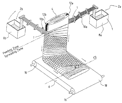
Referring to Figure 1, according to the first embodiment of the present
invention,
a machine and process for producing a cross-lapped flat-tube structure of
crimped continuous filaments includes two separate feeding devices 2a and 2b
located 180 degrees apart from one another; a spreading, extending, and cross-
lapping device 4, which will be called the batt-forming device 4; and a
conveying device 6. A tow 1 of crimped continuous filaments is fed from each
of the feeding devices 2a and 2b to the batt-forming device 4, where the tow 1
is
spread, extended, and cross-lapped. From the batt-forming device 4, a cross-
lapped flat-tube structure of crimped continuous filaments is delivered to the
conveying device 6 and subsequently to the windup equipment.
The feeding devices 2a and 2b each consist of a container 8a and 8b
respectively
in which the tow is stored and a series of rolls 10a and lOb respectively for
spreading and feeding the tow 1 from the containers 8a and 8b to the batt-
forming device 4. Although not shown, a mechanism is used to carry and drive
the feeding devices 2a and 2b wrapping around the batt-forming device 4
continuously either in a clockwise or counter-clockwise direction for
producing
-6-
CA 02454973 2004-01-07
a continuous cross-lapped flat-tube structure of crimped continuous filaments.
Such a mechanism is not shown since it is not the spirit or an essential part
of the
present invention.
Referring to Figures 2 to 5, the batt-forming device 4 includes two groups of
pin-covered conveyors 12a and 12b, and two curved plates 14a and 14b between
which the two groups of conveyors are arranged. The first group 12a is
arranged
near one edge of each of the plates 14a and 14b, and the second group 12b is
arranged on the opposite edge of each of the plates 14a and 14b. Each group of
the conveyors 12a and 12b extend a portion beyond the edges of plates 14a and
14b for engagement with the tows 1 of crimped continuous filaments, which are
wrapped around the batt-forming device 4. As shown in Figures 3 and 4, 12a and
12b each consist of two groups of conveyors. A slower-moving conveyor is in
the feeding zone located in the upper section of the batt-forming device 4,
and a
faster-moving conveyor in the spreading zone is located in the lower section
of
the batt-forming device 4. As shown in Figures 3 and 4, the conveyors in the
upper section of the batt-forming device 4 within the feeding zone, indicated
as
Fca and Fcb, which comprise two separate but identical conveyors, are driven
by
rolls of slower but identical rotating speed in both 12a and 12b. Therefore,
the
surface speeds of conveyors in the feeding zone are identical at 12a and 12b.
The advantage of the two separate conveyors in the feeding zone is to provide
additional anchor points and supports of the engaged tow band in the feeding
zone so that they can prevent a potential filament entanglement problem within
the tow band during the engaging and transferring processes within the feeding
zone. These two conveyors identified in each of Fca and Feb respectively as
shown have identical construction and surface speed, and the conveyors are
parallel to each other. The conveyor belt surfaces are covered with coarse
pins
extended on the surfaces to provide enough friction to hold filaments of the
tow 1
in place and transport them to the spreading zone. Because there are two
conveyors for each side of the feeding zone, there are also two corresponding
pin-wheels for each of La and Lb respectively at the bottom of each conveyor
Fca and Fcb in the feeding zone in 12a and 12b having fine pins on the surface
with surface speed faster than that of the conveyors in the feeding zone to
pick up
filaments from the respective conveyors as shown in Figures 3 and 4.
As the tow 1 of crimped continuous filaments is engaged by coarse pins on the
conveyors Fca and Fcb in the feeding zone and moved downward at slow speed,
filaments maintain their positions parallel to each other in the tow 1 without
separation or spreading. When the leading edge of the tow 1 reaches the
joining
line between the bottom of Fca and Fcb and the pin-wheels La and Lb, the
filaments in the leading edge of the tow 1 are caught by fine pins on the
surface
of the fast-rotating pin-wheels La and Lb.
Figure 5 shows that, because the surface speed of the pin-wheel La is faster
than
that of the conveyor Fca in the feeding zone, the filaments are caught and
picked
up from the tow band and are separated from the majority of the filaments in
the
-7-
CA 02454973 2004-01-07
tow 1, which is still being held by coarse pins on the conveyors in the
feeding
zone. In a continuous operation, the rest of the tow band is moved downward
continuously by conveyors in the feeding zone toward the fast-moving pin-
wheel La until all filaments are picked up. Since the pin-wheel La picks up
filaments in sequence and at a faster speed, the filaments on pin-wheel La are
also parallel to each other but are further apart. The resulting spread batt
on
pin-wheel La's surface is much thinner than the thickness of the original tow
1
fed onto the conveyors in the feeding zone. As the leading edge of the spread
batt moving downward reaches the joining line between the pin-wheels La and
Lb and the top of the conveyors Sca and Scb in the spreading zone, the
filaments
in the leading edge of the spread batt on pin-wheels La and Lb are caught by
the
finer pins on the surface of the even faster-moving conveyors Sca and Scb in
the
spreading zone. The conveyors Sea and Scb are different from the conveyors
Fca and Feb in the feeding zone, and each forms only a single wider conveyor.
Once again, because the surface speed of the conveyors Sca and Scb in the
spreading zone is faster than that of the pin-wheels La and Lb, the filaments
are
caught and picked up by finer pins on conveyors Sca and Seb in the spreading
zone from the leading edge of the spread batt and are separated from the
majority
of the filaments in the spread batt which are still being held by fine pins on
the
pin-wheels La and Lb. In a continuous operation, the rest of the spread batt
is
moved downward continuously by pin-wheels La and Lb toward the faster-
moving conveyors Sea and Scb in the spreading zone until all filaments are
picked up by finer pins in conveyors Sca and Scb in the spreading zone. The
resulting spread structure on conveyors Sca and Scb in the spreading zone is a
uniform, thin batt of spread crimped continuous filaments which are parallel
to
each other.
The ratio of the surface speed of the conveyors Sca and Scb in the spreading
zone
to that in the feeding zone is defined as the spread ratio. The spread ratio
determines the filament orientation angle and the cross-lapped layer angle, as
will be described later. The surface speed of the pin-wheels La and Lb is
faster
than that of the conveyors Fca and Fcb in the feeding zone, but is slower than
that
of the conveyors Sca and Scb in the spreading zone. Since the pin-wheels La
and
Lb act as a separating wheel to separate filaments from the tow bundle and to
transfer the resulting thinner batt to the conveyors Sca and Scb in the
spreading
zone for further spreading, the speed of the pin-wheels La and Lb does not
change the spread ratio of the final product. However, the pin-wheel speed is
adjusted based on the tow denier, crimp level, and cohesiveness of the
filaments
so that the filaments can be separated from the tow bundle without
entanglement
or damage for the uniform spreading operation.
In another aspect of the present invention, referring to Figure 6, the batt-
forming
device 4 consists of four groups of conveyors 12a, 12a-1, 12b, and 12b-1
instead
of the two described above; each group has two conveyors in the feeding zone
and one conveyor in the spreading zone. The composition of each group of
conveyors in Figure 6 is identical to that described in Figure 2 identified as
12a
-8-
CA 02454973 2004-01-07
and 12b. The components of these two additional groups of conveyors 12a-1 and
12b-1 are the same as those of 12a and 12b described in Figures 3 to 5 with
the
exception that 12a-1 and 12b-1 are opposite to each other but are located 90
degrees away from 12a and 12b respectively. Identical to that of 12a and 12b
shown in Figure 3, 12a-1 and 12b-1 each has a group of pin-wheels La-1 and
Lb-1 respectively in between the feeding zone and spreading zone. With these
two additional groups of conveyors and wheels, the principle operation of the
batt-forming device 4 is identical to that described above, but a wider flat-
tube
structure can be made evenly from a wider batt-forming device 4. Because the
tow of crimped continuous filaments has very good cohesion between the
filaments, it is difficult to separate the individual filaments from each
other if the
distance between the two conveyors in which the tow 1 is engaged is large. By
reducing the distance between the two adjacent conveyors as illustrated in
Figure
6, the filament cohesive force between the two supporting conveyors can be
overcome by the spreading force asserted on the filaments. And as the filament
cohesive force is overcome, the crimped continuous filaments can be spread
evenly and smoothly, instead of sporadically, when cohesive force is
overridden
to form a uniform flat-tube structure. More detailed illustrations will be
given
below.
As the width of the batt-forming device 4 increases, further additional groups
of
conveyors can be installed evenly around the surfaces of the two curved plates
14a and 14b, to a total of 6, 8, 10, etc., groups of conveyors. There is no
limitation to the number of groups of conveyors that can be used in the batt-
forming device 4.
Referring to Figure 1, the conveying device 6 includes two rolls 16 and an
endless belt 18 mounted on and driven by the rolls 16 for delivering the cross-
lapped flat-tube structure produced by the batt-forming device 4.
The operation of the first embodiment of the present invention is described in
Figure 1 in the following sequences.
(1) There are two separate feeding devices 2a and 2b located opposite to each
other relative to the batt-forming device 4. In a continuous operation, a
first portion of the tow 1 of crimped continuous filaments is delivered from
the container 8a through feeding and spreading rolls l Oa to conveyor 12a in
the feeding zone. Soon after the first portion of the tow 1 is engaged with
the moving conveyor 12a, it is transported downward at a speed slower
than that of the tow 1 delivery speed from 10a. In an identical operation,
and travelling in the same clockwise direction around the batt-forming
device 4 simultaneously, a first portion of the tow 1 of crimped continuous
filaments is delivered from container 8b through feeding and spreading
rolls I Ob to conveyor 12b in the feeding zone. Soon after the first portion
of the tow 1 is engaged with moving conveyor 12b, it is transported
downward at a speed slower than that of the tow 1 delivery speed from l Ob.
-9-
CA 02454973 2004-01-07
When the feeding device 2a is rotated 180 degrees clockwise in front of the
batt-forming device 4, a second portion of the tow 1 of crimped continuous
filaments is delivered from container 8a through feeding and spreading
rolls l0a and is engaged with conveyor 12b in the feeding zone. In the
meantime, the feeding device 2b is also rotated 180 degrees clockwise
around the back of the batt-forming device 4, and a second portion of the
tow 1 of crimped continuous filaments is delivered from container 8b
through feeding and spreading rolls 10b to conveyor 12a in the feeding
zone.
(2) The leading edge of the tow 1 of crimped continuous filaments at the
bottom of the conveyors in the feeding zone is picked up by pin-wheels La
and Lb respectively at faster surface speed. Therefore, filaments are being
spread under tension and deposited onto conveyors in the spreading zone
on both 12a and 12b having an even faster surface speed than La and Lb.
As the tows 1 of crimped continuous filaments are delivered continuously
from conveyors in the feeding zone of 12a and 12b, a continuous spread
flat tube of continuous filaments is formed in conveyors in the spreading
zone of 12a and 12b. By adjusting the ratio of the surface speed of the
conveyors in the spreading zone to that in the feeding zone, which is
expressed as the spread ratio, and adjusting the width of tow bands and the
delivery speed of the tows 1 to the batt-forming device 4, one can change
the basis weight of the flat-tube structure and the inclined angle A of the
filaments relative to the CD direction as shown in Figure 1. Ideally, a 45-
degree angle will provide equal tensile strength in MD and CD directions at
a ratio close to 1:1 for best balance of tensile strength. The present
invention can achieve such an ideal angle of 45 degrees. To meet the
specific requirements of the end product, one can adjust the angle A
between approximately 10 and 70 degrees to provide the desired tensile
strength, stretchability, and loft.
(3) In a continuous rotating motion, the feeding device 2a is moving to the
back of the batt-forming device 4 in Figure 1 or facing the curved plate 14b
in Figure 2; while the feeding device 2b is moving to the front of the batt-
forming device 4 in Figure 1 or facing the curved plate 14a in Figure 2. A
third portion of the tow 1 of crimped continuous filaments is delivered
from container 8a through feeding and spreading rolls l0a and is engaged
with moving conveyor 12a in the feeding zone. Simultaneously, in an
identical operation, a third portion of the tow 1 of crimped continuous
filaments is delivered from container 8b through feeding and spreading
rolls lOb and is engaged with moving conveyor 12b in the feeding zone.
This process is repeated many times exactly as described in sequences (1),
(2), and (3) above; therefore, a continuous flat-tube structure of spread
crimped continuous filaments is formed in the batt-forming device 4 and
subsequently delivered to conveyor device 6.
-10-
CA 02454973 2004-01-07
Referring to Figures 7 to 10 as the illustrations of one aspect of the present
invention, two 0.25-meter-wide tows of crimped continuous filaments are
delivered from 8a and 8b respectively, wrapping around a 2-meter-wide batt-
forming device 4 at a speed of 0.25 meter per second, which is identical to
that of
the conveyor speed in the spreading zone. The conveyor speed in the feeding
zone is 1/8 of that of the conveyors in the spreading zone, or 0.03125 meter
per
second, resulting in a spread ratio of 8. As shown in Figures 7 to 10, in
every
eight seconds, tows 1 delivered from containers 8a and 8b have traveled the
distance of 2 meters between conveyors 12a and 12b, with Figure 7 showing the
first 0 second of traveling, Figure 8 showing the 8th second of traveling,
Figure 9
showing the 16" second of traveling, and Figure 10 showing the 24t' second of
traveling. During this period, the first portions of the engaged tows 1 have
been
spread from 0.25 meter to 2 meters in the spreading zone. Because 8a and 8b
are
traveling in the same direction but are 180 degrees apart, each spread tow
pattern
is also the opposite and mirror image of the other. However, when the two
spread tow patterns are super-imposed on each other as in the continuous
operation involving two separate feeding devices in the present invention, a
continuous flat tube of spread crimped continuous filaments, as shown in
Figure
1, is formed continuously.
Referring to Figure 6 as another illustration of other aspects of the present
invention using four groups of conveyors instead of two as described above,
two
0.25-meter-wide tows I of crimped continuous filaments are delivered from 8a
and 8b respectively, wrapping around a 2-meter-wide batt-forming device 4 at a
speed of 0.25 meter per second, which is identical to that of the conveyor
speed
in the spreading zone. Since all four pin conveyors in the feeding zone are
moving at the same speed and all four pin conveyors in the spreading zone are
moving at the same but faster speed, the operation is the same as in the above
illustration. For example, after 8 seconds, the first portion of tow 1 engaged
with
12a in Figures 7 to 10 having a 2-meter-wide batt-forming device 4 has been
spread from 0.25 meter to 2 meters in the spreading zone, forming a 45 degree
filament orientation angle between 12a and 12b. But adding two more groups of
pin conveyors 12a-1 and 12b-1 as in Figure 6, after 8 seconds, the engaged tow
at
12a also has been spread from 0.25 meter to 2 meters in the spreading zone,
and
the engaged tow at 12b-1 is only spread from 0.25 meter to 1 meter in the
spreading zone because tow 1 engaged with 12b-1 is 4 seconds late after
engaging with 12a. Therefore, the filament orientation is still maintaining 45
degrees, the same as the above, as is shown in Figure 11. Because of this time
delay to reach 12b-1, the spread tow formation is the same whether 12b-1 is
installed in the batt-forming device 4 or not. The same situation can be
applied
with 12a-1 relative to the spread tow formation. The advantage of the
additional
two groups of conveyors 12a-1 and 12b-1 as described previously is reducing
the
distance between engaging conveyors to override the cohesive force exhibited
in
the tow 1 of crimped continuous filaments so that uniform and smooth spreading
can be achieved to form a uniform flat-tube structure. With a much wider batt-
forming device to make a wider flat-tube structure, additional groups of
-11-
CA 02454973 2004-01-07
conveyors in the feeding zone and the spreading zone are beneficial to
overcome
the cohesive force of the crimped continuous filaments for a successful
spreading operation.
In yet another aspect of the present invention, referring to Figure 12, the
two
separate tows I being fed from containers 8a and 8b respectively have a
different
configuration compared to that shown in Figure 1. The tows 1 shown in Figure 1
and described in this embodiment are very uniform tow bands which can be
characterized as having essentially the same thickness, density, and
continuity
across the width of the tow band. The resulting cross-lapped flat-tube
structure
is a homogeneous, uniform structure in appearance and in properties, having
balanced tensile strength in all directions and providing structural stability
and
stretch recovery properties. However, the tow bands shown in Figure 12 are
separated into many small bundles of filaments by an additional special
device,
such as separating guide pins or guide rolls in 10a and l Ob respectively,
before
feeding them to the batt-forming device 4. The resulting bundles of filaments
within the tow band are separated from each other with a definite gap between
them, with the distance depending on the design of the separating device.
These
heterogeneous tow bands consisting of many small bundles of filaments and
space in between them can form a heterogeneous cross-lapped flat-tube
structure
of crimped continuous filaments using the same machine and process of the
present invention. The resulting heterogeneous cross-lapped flat-tube
structure
has essentially the same structure and characteristics, mainly having a
balance of
tensile strength in all directions and providing structural stability and
stretch
recovery properties with some exceptions. There are many empty spaces
without filaments formed along each layer of the batt and many holes created
within the cross-lapped structure, as shown in Figure 12. The resulting cross-
lapped flat-tube structure has the appearance of a.loosely woven structure in
the
form of mesh wire or fishing net, with many holes between filament cross-over
points. This structure provides unique attributes, such as high air
permeability
through open holes for good breathability with low density, resiliency, and
good
support, which can be used as components to satisfy important requirements in
mattress and furniture applications. This further demonstrates the flexibility
and
versatility of the present invention. This aspect of the present invention can
be
used singularly or in combination with other aspects of the present invention
as
described in all embodiments of the present invention.
In yet another aspect of the present invention, referring to Figures 13 and
14,
there are no limitations on the denier, homogeneity, and width of the tow
bands
to be used with the present invention. Contrary to the aspect described above
as
illustrated in Figure 12, the present invention can also provide a very
uniform
flat-tube structure with very little or no cross-lapped marks as normally
appear in
a conventional cross-lapped structure described in prior art. Instead of using
the
usual thick and narrow tow band, a thin but wider tow band can be used to
achieve a much more uniform flat-tube structure with essentially no cross-
lapped
marks between layers. For example, by using a tow band width of 75 cm (H) (as
-12-
CA 02454973 2004-01-07
shown in Figure 13) instead of the usual 25 cm (h) (as shown in Figure 14) as
described above for the feeding tow for the batt-forming device 4, one can
minimize or eliminate the cross-lapped marks on the flat-tube structure.
Because
the feeding tow as shown in Figure 13 is three times wider, it will overlap
three
times in the feeding zone of the batt-forming device before reaching the
spreading zone; hence, the marks on the over-lapped layers in the feeding zone
are virtually eliminated compared to the obvious heavy marks appearing on the
two adjacent thick and narrow tow bands. The resulting flat-tube structure
from
this wide tow band has essentially no cross-lapped marks. This further
demonstrates the flexibility and versatility of the present invention.
The cross-lapped angle between the two cross-lapped layers is ideally 90
degrees
for equal strength in MD and CD directions. Other cross-lapped layer angles
can
be achieved by this invention by adjusting the traveling speed of feeding
devices
2a and 2b wrapping around the batt-forming device 4 and the spread ratio of
the
conveyor speeds between spreading zone and feeding zone. To meet the specific
requirements of the end use, one can achieve the cross-lapped layer angles
between about 20 and 140 degrees for specific desired tensile strength,
stretchability, and loft. It is desirable that the spread tow leaves the batt-
forming
device 4 for the conveying device 6 when the section of the tow 1 between the
first and second portions is at an appropriate angle from the section of the
tow 1
between the second and third portions. The angle will determine the tensile
strength ratio between MD and CD directions of the cross-lapped flat-tube
structure.
There is a very important distinction between the spread cross-lapped flat-
tube
structure of the present invention compared to conventional cross-lapping
batting by the process described in the prior art mentioned earlier. The flat
tube
of the present invention is an endless tube structure with very good
uniformity
throughout the entire structure, including edges and center, with dimensional
stability, good stretchability, and high loft as shown in Figure 15, whereas
the
batt created by a conventional cross-lapping method is a folding-layer
structure
which has the appearance of fish scales which can be peeled off layer by layer
as
shown in Figure 16, with deficiencies of uniformity, poor cohesion between
layers, poor balance of MD and CD tensile strength, and inadequate dimensional
stability.
As shown in Figure 1, the feeding devices 2a and 2b are located at identical
height in the feeding zone relative to the batt-forming device 4, and they are
separated by 180 degrees and rotate around the batt-forming device 4 in a
clockwise direction. However, the feeding devices 2a and 2b can be at
different
heights in the feeding zone relative to the batt-forming device 4, be
different
degrees apart, and rotate in different directions around the batt-foiming
device 4.
As long as both feeding devices are located above the dividing line between
the
feeding zone and spreading zone, a flat-tube structure from spread tow 1 of
crimped continuous filaments can be produced by the present invention.
- 13 -
CA 02454973 2004-01-07
Referring to Figure 17, according to a second embodiment of the present
invention, a machine and process for producing a cross-lapped flat-tube
structure
of crimped continuous filaments includes a single feeding device 2; a
spreading,
extending, and cross-lapping device 4, which will be called the batt-forming
device 4; and a conveying device 6. A tow 1 of crimped continuous filaments is
fed from the feeding device 2 to the batt-forming device 4, where the tow 1 is
spread, extended, and cross-lapped. From the batt-forming device 4, a cross-
lapped flat-tube structure of crimped continuous filaments is delivered to the
conveying device 6.
The feeding device 2 consists of a container 8 in which the tow 1 is stored
and a
series of rolls 10 for spreading and feeding the tow 1 from the container 8 to
the
batt-forming device 4. Although not shown, a mechanism is used to carry and
drive the feeding device 2 wrapping around the batt-forming device 4
continuously, either in a clockwise or counterclockwise direction for
producing
a continuous cross-lapped flat-tube structure of crimped continuous filaments.
The batt-forming device consists of two groups of pin-covered conveyors 12a
and 12b and two curved plates as shown in Figures 2 to 4. The description of
the
composition and operation of the batt-forming device 4 is identical to that in
the
first embodiment of the present invention and is shown in Figures 2 to 4.
The operation of the second embodiment of the present invention is similar to
that of the first embodiment of the present invention except a single
container is
needed as described as container 8a in the first embodiment of the present
invention. The other exception is that the conveyor speed of 12a and 12b in
the
feeding zone is even slower than that of the tow delivery speed from the
series of
rolls 10, for example, 1/16 instead of 1/8, as in the case of the first
embodiment.
Because of the speed difference, a single feeding device can cover the total
area
needed for two feeding devices as shown in Figures 7 to 10. In order to keep a
spread ratio of 8, the conveyor speed in the spreading zone is eight times
faster
than that of the conveyor speed in the feeding zone. As result, unlike the
illustration in Figures 7 to 10, the tow 1 speed from container 8 wrapping
around
the batt-forming device 4 is actually twice (2x) that of the conveyor speed in
the
spreading zone. In other words, in eight seconds, container 8 has made one
complete circle (360 degrees) around the batt-forming device 4 and engaged a
third portion of the tow 1 with 12a instead of just traveling half a circle
(or 180
degrees) or engaging a second portion of tow 1 with 12b. This illustrates the
flexibility and versatility of this machine and process to make flat-tube
structures
with various basis weights, filaments and cross-lapped angles, and
productivity
by adjusting various combinations of the tow 1 denier, the feeding speed from
container 8, and the spread ratio of the batt-forming device 4.
Referring to Figure 18, according to a third embodiment of the present
invention,
a machine and process for producing a cross-lapped flat-tube structure of
-14-
CA 02454973 2004-01-07
crimped continuous filaments includes four separate feeding devices 2a and 2b
located at the same height relative to the batt-forming device 4, both
rotating in
the same direction as shown in Figure 1, and 2c and 2d located at the same
height
but higher than that of 2a and 2b relative to the batt-forming device 4, both
rotating in the same direction, which could be the same as or different from
the
direction of 2a and 2b.
As shown in Figure 18, 2a and 2b rotate clockwise around the batt-forming
device 4 and both are located just above the dividing line between the feeding
zone and the spreading zone. The other two feeding devices 2c and 2d rotate
counter-clockwise around the batt-forming device 4 and are located higher
above both 2a and 2b and also further away from the dividing line between the
feeding zone and the spreading zone.
The procedure of engaging and spreading the tows 1 of crimped continuous
filaments from containers 8a and 8b is identical to that of the three
sequences (1),
(2), and (3) described previously in the first embodiment of the present
invention
shown in Figure 1. The other two feeding devices 2c and 2d are located
opposite
to each other but above 2a and 2b relative to the batt-forming device 4. In a
continuous operation, a first portion of the tow 1 of crimped continuous
filaments is delivered from the container 8c through feeding and spreading
rolls
l Oc to conveyor 12a in the feeding zone. Soon after the first portion of the
tow 1
is engaged with the moving conveyor in the feeding zone 12a, the engaged
portion of the tow 1 is being transported downward at a slower speed than that
of
the tow 1 delivery speed from l Oc. Simultaneously in an identical operation,
and
traveling in the same counter-clockwise direction around the batt-forming
device
4, a first portion of the tow 1 of crimped continuous filaments is delivered
from
container 8d through feeding and spreading rolls lOd to conveyor 12b in the
feeding zone. Soon after the first portion of the tow 1 is engaged with the
moving conveyor 12b in the feeding zone, the engaged portion of the tow 1 is
being transported downward in similar fashion as the engaged tow 1 from
container 8c. When feeding device 2c is rotated 180 degrees counterclockwise
around the back of the batt-forming device 4, or facing the curved plate 14b
in
Figure 2, a second portion of the tow 1 of crimped continuous filaments is
delivered from container 8c through feeding and spreading rolls 10c and is
engaged with conveyor 12b in the feeding zone. In the meantime, the feeding
device 2d is also rotated 180 degrees counterclockwise around the front of the
batt-forming device 4 or facing the curved plate 14a in Figure 2, and a second
portion of the tow 1 of crimped continuous filaments is delivered from
container
8d through feeding and spreading rolls 10d and engaged with conveyor 12a in
the feeding zone. The process is repeated with the third and fourth portions
of
tows 1 of crirnped continuous filaments from feeding devices 2c and 2d and the
process is repeated continuously.
The engaged tows 1 in the feeding zone delivered from containers 8c and 8d are
transferred along the downward moving conveyors 12a and 12b in the feeding
- 15 -
CA 02454973 2004-01-07
zone for a distance until they reach close to the dividing line of the feeding
zone
and spreading zone and are laid over and combined with tows I from feeding
devices 2a and 2b.
The leading edges of the combined tows 1 of crimped continuous filaments at
the
bottom of the conveyors in the feeding zone are picked up by pin-wheels La and
Lb, as shown in Figures 3 to 5, at faster surface speed. Therefore, filaments
are
being spread under tension and deposited onto conveyors 12a and 12b in the
spreading zone, with both having faster surface speed than that of La and Lb.
As
the tows 1 of crimped continuous filaments are delivered continuously from
conveyors 12a and 12b in the feeding zone, a continuous cross-lapped flat-tube
of spread crimped continuous filaments is formed in conveyors in the spreading
zone of 12a and 12b of the batt-forming device 4, and subsequently delivered
to
conveying device 6. This part of the spreading, extending, and cross-lapping
process is identical to that described in the first embodiment of the present
invention.
The locations of the feeding devices 2a and 2b can be at the same or different
heights above the dividing line between the feeding zone and the spreading
zone.
They may rotate in the same or different direction either clockwise or
counterclockwise around the batt-forming device 4. The locations of feeding
devices 2c and 2d are higher than those of 2a and 2b but each can be at the
same
or different heights and rotate in the same or different directions around the
batt-forming device 4. Once again, the ratio of surface speed of the conveyors
in
the spreading zone to that in the feeding zone is expressed as the spread
ratio.
The spread ratio determines the filament orientation angle vs. the CD
direction
and the cross-lapped angle between layers of the flat-tube structure.
Referring to Figure 19, according to a fourth embodiment of the present
invention, a machine and process for producing a flat-tube structure of spread
crimped continuous filaments includes two separate feeding devices 22a and
22b.
Each consists of multiple containers 9a, 10a, and 11 a in 22a, and 9b, l Ob,
and
l lb in 22b; a spreading, extending and cross-lapping device 4, now called the
batt-forming device 4 comprising a feeding zone and spreading zone, with
composition identical to that in Figures 2 to 4, and a conveying device 6. The
number of containers in feeding devices 22a and 22b varies from 2 to 100,
depending on the denier and the width of the tow I in each container. A tow 1
of
crimped continuous filaments is fed from each of the containers in feeding
devices 22a and 22b to the batt-forming device 4 where the tow 1 is spread,
extended and cross-lapped into a flat-tube structure and is finally delivered
to
conveying device 6. The batt-forming device 4 and conveying device 6 in Figure
19 are identical to that in Figures 1 and 18. The mechanism of spreading,
extending and cross-lapping according to this embodiment of the present
invention is the same as described in Figure 1, except multiple numbers of
tows 1
are fed to the batt-forming device 4 from each of the feeding devices 22a and
22b.
-16-
CA 02454973 2004-01-07
More than two additional feeding devices as described as 22a and 22b in Figure
18 can be used with the present invention to make various basis weights and
compositions of the flat-tube structure.
To illustrate the flexibility and versatility of the present invention,
referring to
Figure 20, a feeding mechanism can consist of a track circle around the batt-
forming device 4, which is fed by feeding devices 2 moving around the track at
a
pre-determined speed. If desired, for convenience, as shown in Figure 20, the
conveyors in the batt-forming device 4 can move upward instead of downward
as shown in Figure 1, so that the conveyors in the feeding zone are at the
lower
level and the conveyors in the spreading zone are at the upper level. As a
result,
the conveying device 6 and windup rolls 61 are also located at the higher
level of
the machine. The composition of the batt-forming device 4 is identical to that
in
Figure 1 with the same components as in Figures 2 to 4, except the conveyors
in
the feeding zone and the spreading zone are moving upward instead of
downward. The principle of spreading, extending, and cross-lapping is exactly
the same as that of the first embodiment of the present invention.
Referring to Figure 21, according to a fifth embodiment of the present
invention,
a commercially feasible and economically viable machine and process for
producing a flat-tube structure of spread tow 1 of crimped continuous
filaments
includes a system composed of a batt-forming device 4, a conveying device 6,
and a windup device 61, all connected to a rotating platform, and two or more
stationary feeding devices 2. The composition of the batt-forming device 4 is
identical to that in Figure 1, with the same components as in Figures 2 to 4,
except the conveyors in the feeding zone and spreading zone are moving upward
instead of moving downward. The principle of spreading, extending, and
cross-lapping is exactly the same as that of the first embodiment of the
present
invention. As the platform rotates in either a clockwise or counterclockwise
direction at a pre-determined speed, tows 1 of crimped continuous filaments
are
fed from stationary feeding devices 2 wrapping around the conveyors in the
feeding zone at the lower level of the rotating batt-forming device 4. These
engaged tows I are then spread in the spreading zone on the upper level and
subsequently delivered to conveying device 6, followed by windup device 61.
The ratio of the surface speed of the conveyors in the spread zone to that in
the
feeding zone is expressed as the spread ratio. Once again, the basis weight of
the
flat-tube structure, the angle between the filaments and the CD direction of
the
flat tube, and the cross-lapped angle between layers are determined by the
combinations of the feeding speed of the tows, the width of the tow 1, and the
spread ratio. The feeding devices 2 can be at the same level as shown in
Figure
21, or in different platforms with various heights so that each tow 1 can be
fed in
different heights in the feeding zone of the batt-forming device 4. The number
of
containers in each feeding device 2 can vary from 2 to 100, depending on the
denier and the width of the tow 1 in each container.
- 17-
CA 02454973 2004-01-07
The rotating batt-forming device in Figure 21 can be driven by some other
means
other than the rotating platform as shown. The batt-forrning device 4 also can
be
arranged in the same configuration as in Figure 1, where the conveyors in both
the feeding zone and the spreading zone are moving downward, so that tows can
be fed from the stationary feeding devices 2 to the feeding zone and
transferred
to the spreading zone one floor below. Subsequently, the spread flat tube is
delivered to the conveying device 6 and windup unit 61 at the lower floor.
Definition of terms:
A. Stretch recovery: A batting or nonwoven fabric is stretched to 150% to
length L2 from the original length, Lo, and the stress is
released. The recovery length, L1, is measured after 10
minutes' relaxation.
The percent recovery, R, is calculated as:
R={ 1-(L 1-Lo)/(L2-Lo)} x 100
When Ll = L2, there is 0% recovery.
When L1 = Lo, there is 100% recovery.
The measurement is determined in both MD and CD
directions of the sample. The higher the percent recovery.
the better the stretchability.
B. Loft: Loft is defined as thickness per unit weight. For example, inch per
oz.
per square yard, or mm. per gram per square meter.
C. Dimensional stability: The ability to maintain the size, i.e., width,
length
and height, during processing and in use.
D. Tensile strength: The ability to withstand the stress applied on a sample
without breaking.
Examples
Example 1
Referring to Figure 1, a tow 1 of crimped continuous filaments with 100,000
filaments and total denier of 600,000 having a width of 0.125 meter is fed
from
container 8a through a series of feeding and spreading rolls l0a which widen
it to
a 0.25-meter tow band, then wrap it clockwise around a 2-meter-wide batt-
forming device 4 and engage it with conveyor 2a in the feeding zone at a speed
equal to 0.25 meter per second. The feeding zone conveyor surface speed is
about 0.03125 meter per second, which is about 1/8 of the feeding speed of the
- 18-
CA 02454973 2004-01-07
tow I wrapping around the batt-forming device 4. The tow 1 is spread by
conveyor 12a in the spreading zone at a surface speed of 0.25 meter per
second,
resulting in a spread ratio of 8, which is equal to the conveyor surface speed
in
the spreading zone divided by the conveyor surface speed in the feeding zone.
By the time the tow band travels 2 meters to reach and engage with conveyor
12b
in the feeding zone, the first portion of the tow 1 at 12a has already been
spread
from 0.25 meters to 2 meters wide to form a batt with a 45-degree angle
relative
to the CD direction. Therefore, the original crimp in the continuous filaments
is
being extended, and the individual filaments in the tow 1 are spread and
separated from each other. The first portion of the original 0.25-meter-wide
tow
band becomes a 2-meter spread and extended batt. Simultaneously, a second
tow band of crimped continuous filaments with 100,000 filaments and total
denier of 600,000 having a width of 0.25 meters is fed from container 8b
through
a series of feeding and spreading rolls 10b wrapping from the opposite
position
around the same 2-meter-wide batt-forming device 4 and engaged with conveyor
12b in the feeding zone at a speed equal to that of container 8a. A second
spread,
extended batt is formed similar to that of the first spread, extended batt.
The two
spread, extended batts form a cross-lapped structure with a cross-lapped angle
about 90 degrees between the two batts. At this 90-degree angle, the cross-
lapped structure has equal strength in both MD and CD directions, good stretch
recovery properties, and high loft. In a continuous operation, these two tow
bands from two separate feeding devices 8a and 8b make a continuous flat-tube
structure as shown in Figure 13, with basis weight of about 100 grams per
square
meter. This flat-tube structure has layers wrapping around in continuous
tubular
form which cannot be peeled off, in contrast to the case of the conventional
cross-lapped structure.
Example 2
Referring to Figure 1, a tow 1 of crimped continuous filaments with 100,000
filaments and total denier of 600,000 as in Example 1 is fed to the batt-
forming
device 4 at the same speed as in Example 1. A second tow 1 is also identical
to
that of Example 1 and is fed to the batt-forming device 4 as described in
Example
1. The only exception is that the spread ratio is 4 instead of 8 as in Example
1.
The resulting spread flat-tube structure has filament orientation of about a
27-
degree angle relative to the CD direction. The flat-tube structure has a cross-
lapped angle between layers of about 54 degrees.
Example 3
Referring to Figure 1, a tow 1 of crimped continuous filaments with 100,000
filaments and total denier of 600,000 as in Example 1 is fed to the batt-
forming
device at speed as in Example 1. A second tow I identical to that of Example 1
is
fed to batt-forming device 4 as described in Example 1. The only exception is
that the spread ratio is 12 instead of 8 as in Example 1. The resulting spread
flat-tube structure has a filament orientation of about a 56-degree angle
relative
-19-
CA 02454973 2004-01-07
to the CD direction, and a cross-lapped angle between layers of about 112
degrees.