Note: Descriptions are shown in the official language in which they were submitted.
CA 02455011 2004-01-09
BITUMINOUS FROTH INLINE STEAM INJECTION PROCESSING
FIELD OF THE INVENTION
This invention relates to bitumen processing and more particularly is related
to
heating bituminous froth using inline steam injection.
BACKGROUND TO THE INVENTION
In extracting bitumen hydrocarbons from tar sands, one extraction process
separates bitumen from the sand ore in which it is found using an ore washing
process generally referred to as the Clark hot water flotation method. In this
process, a bitumen froth is typically recovered at about 150 F and contains
residual air from the flotation process. Consequently, the froth produced from
the
Clark hot water flotation method is usually described as aerated bitumen
froth.
Aerated bitumen froth at 150 F is difficult to work with. It has similar
properties to
roofing tar. It is very viscous and does not readily accept heat.
Traditionally,
processing of aerated bitumen froth requires the froth to be heated to 1900 to
200 F and deaerated before it can move to the next stage of the process.
Heretofore, the aerated bitumen froth is heated and de-aerated in large
atmospheric tanks with the bitumen fed in near the top of the vessel and
discharged onto a shed deck. The steam is injected below the shed deck and
migrates upward, transferring heat and stripping air from the bitumen as they
contact. The method works but much of the steam is wasted and bitumen
droplets are often carried by the exiting steam and deposited on nearby
vehicles,
facilities and equipment.
SUMMARY OF THE INVENTION
The invention provides an inline steam heater to supply heated steam to a
bitumen froth by direct contact of the steam to the bitumen froth resulting in
superior in efficiency and environmental friendliness than processes
heretofore
employed.
CA 02455011 2009-10-06
-2-
In one of its aspects, the invention provides an inline bitumen froth steam
heater system including at least one steam injection stage, each steam
injection stage followed by a mixing stage. Preferably, the mixing stage
obtains a mixing action using static mixing devices, for example, using baffle
partitions in a pipe. In operation, the invention heats the bitumen froth and
facilitates froth deaeration by elevating the froth temperature. In operation
the
bitumen froth heating is preferably obtained without creating downstream
problems such as emulsification or live steam entrainment. The froth heater is
a multistage unit that injects and thoroughly mixes the steam with bitumen
io resulting in solution at homogenous temperature. Steam heated to 300
degrees Fahrenheit is injected directly into a bitumen froth flowing in a
pipeline where initial contact takes place. The two incompatible substances
are then forced through a series of static mixers, causing the steam to
contact
the froth. The mixer surface area and rotating action of the material flowing
through the static mixer breaks the components up into smaller particles,
increasing contact area and allowing the steam to condense and transfer its
heat to the froth. The reduction in bitumen viscosity also allows the release
of
entrapped air.
CA 02455011 2010-08-03
-2a-
In another aspect, there is provided an apparatus for heating a bitumen froth
by steam, the apparatus comprising: a heater body comprising a bitumen froth
inlet for receiving the bitumen froth, a steam inlet for receiving the steam,
and
a mixture outlet; and a static mixer body having first and second spaced ends
and forming an enclosed passageway extending between the first and second
ends, wherein the first end is in communication with the mixture outlet, the
static mixer body supporting a plurality of baffles disposed within the
enclosed
passageway to effect a mixing action of the bitumen froth and the steam
flowing through the enclosed passageway thereof to form a heated feed,
to wherein the steam inlet is disposed to inject the steam into the heater
body
towards the enclosed passageway in a direction generally parallel to a
longitudinal axis of the enclosed passageway, and wherein the apparatus is
operably configured to: (a) force the bitumen froth and the steam through the
mixture outlet into the enclosed passageway, (b) force the bitumen froth and
the steam through the enclosed passageway from the first end to the second
end so as to cause the steam to contact the bitumen froth so as to form the
heated feed, and (c) force all of the heated feed to exit through the second
end of the static mixer body.
In another aspect, the apparatus may have the baffles are disposed within the
static mixer body to impart a lateral, radial, tangential or circumferential
directional component to the bitumen froth and the steam, the directional
component changing repeatedly along a length of the enclosed passageway.
In various aspects, the apparatus may further comprise a steam flow control
valve to control a rate of supplying the steam to the steam inlet from a steam
source.
In various aspects, the apparatus may further comprise a first temperature
transmitter disposed to measure a temperature of the heated feed exiting the
enclosed passageway of the static mixer, wherein the steam flow control
valve is responsive to the measured temperature of the heated feed.
CA 02455011 2010-08-03
-2b-
In various aspects, the apparatus may further comprise a steam flow pressure
control valve to control a pressure of the steam supplied to the steam inlet
from a steam source.
In further various aspects, the apparatus may further comprise a pressure
transmitter disposed to measure the pressure of the steam supplied from the
steam flow pressure control valve, wherein the steam flow pressure control
valve is operative to maintain the steam supplied to the steam inlet at a
predetermined pressure in response to the measured pressure of the steam
io supplied from the steam flow pressure control valve.
The apparatus may further comprise (a) a condensate source and a steam
source; (b) a condensate mixer operably configured to mix a condensate from
the condensate source with the steam from the steam source for modulating a
temperature of the steam supplied to the steam inlet; and (c) a condensate
flow control valve to control a supply of the condensate to the condensate
mixer.
In various aspects, the apparatus may yet further comprise a second
temperature transmitter disposed to measure the temperature of the steam
supplied to the steam inlet and relay a representation of the measured
temperature of the steam to the condensate flow control valve, wherein the
condensate flow control valve is operative to control the supply of the
condensate to the steam supplied to the steam inlet.
In various aspects, the steam supplied to the steam inlet comprises saturated
steam. In various aspects, the steam supplied to the steam inlet has a
temperature of about 300 F and a pressure of about 90 psi.
In various aspects, the heated feed has a substantially uniform temperature,
which may be about 190 F.
CA 02455011 2010-08-03
-2c-
In another aspect, there is provided an apparatus for heating a bitumen froth
by steam, the apparatus comprising: a heater body comprising walls defining
a chamber of the heater body, a first inlet for introducing the bitumen froth
having a bitumen froth flow into the chamber, and injector inlet for
introducing
the steam having a steam flow into the chamber, and a heater outlet; and a
static mixer body comprising: a mixer inlet and a mixer outlet, the static
mixer
body forming an enclosed passageway extending between the mixer inlet and
the mixer outlet, the mixer inlet being in fluid communication with the heater
to outlet for receiving the bitumen froth and the steam; and mixing means for
mixing the bitumen froth and the steam flowing through the enclosed
passageway of the static mixer body to form a heated feed, wherein the
heater body and the static mixer body are operably configured to: (a) force
the
bitumen froth and the steam through the enclosed passageway from the mixer
inlet to the mixer outlet so as to cause the steam to contact the bitumen
froth
and form the heated feed, and (b) force all of the heated feed to exit through
the mixer outlet.
In various aspects, the mixing means impart a lateral, radial, tangential or
circumferential directional component to the bitumen froth and the steam, the
directional component changing repeatedly along a length of the enclosed
passageway. In various aspects, the mixing means comprises a plurality of
static mixer barriers forming partial walls disposed within the enclosed
passageway.
In various aspects, the steam injected by the injector inlet has a temperature
of about 300 F to about 500 F and a pressure of about 90 to 150 psi, and the
heated feed produced by the static mixer body has a temperature of about
190 F.
In various aspects, the apparatus further comprises a steam flow control valve
to control a rate of the steam flow into the chamber and a first temperature
CA 02455011 2010-08-03
-2d-
transmitter disposed to measure a temperature of the heated feed exiting the
static mixer body, wherein the heater body, the static mixer body, the steam
flow control valve and the first temperature transmitter form a first closed
loop
control system, the steam flow control valve being responsive to the
measured temperature of the heated feed by the first temperature transmitter.
In various aspects, the apparatus further comprises a steam flow pressure
control valve to control a pressure of the steam flow into the chamber and a
pressure transmitter disposed to measure the pressure of the steam flow from
1o the pressure control valve, wherein the heater body, the static mixer body,
the
steam flow control valve, the temperature transmitter, the steam flow pressure
control valve and the pressure transmitter form a second closed loop control
system, the steam flow pressure control valve being responsive to the
measured pressure.
In various aspects, the apparatus further comprises a condensate flow control
valve to control the supply of a condensate to the steam for modulating the
temperature of the steam for injecting by the injector inlet and a second
temperature transmitter disposed to measure the temperature of the steam
supplied to the injector inlet, wherein the heater body, the static mixer
body,
the steam flow control valve, the first temperature transmitter, the steam
flow
pressure control valve, the pressure transmitter, the condensate flow control
valve, and the second temperature transmitter form a third closed loop control
system, the condensate flow control valve being responsive to the
temperature of the steam measured by the second temperature transmitter.
The mixing means may comprise a baffle disposed across the enclosed
passageway, and the steam supplied to the injector inlet comprises saturated
steam.
In another aspect, there is provided a method to heat a bitumen froth by
steam. In this aspect, the method comprises (a) providing a source of steam;
CA 02455011 2010-08-03
-2e-
(b) contacting the steam with a bitumen froth flow within an enclosed
passageway of an inline body; (c) forcing the bitumen froth flow and the steam
through the enclosed passageway so as to cause the steam to mix with the
bitumen froth flow to form a heated feed having a generally uniform
temperature; and (d) forcing all of the heated feed to exit through an outlet
of
the enclosed passageway.
In various aspects, the method may further comprise controlling the rate of
steam supply of the steam contacting the bitumen froth flow to control the
io generally uniform temperature of the heated feed.
In other aspects, the method may also comprise (a) measuring the generally
uniform temperature of the heated feed; and (b) varying the rate of steam
supply of the steam contacting the bitumen froth flow to obtain a target
uniform temperature of the heated feed. In other aspects, the method may
further comprise controlling the pressure of the steam supply of the steam
contacting the bitumen froth flow. In yet other aspects, the method may
further
comprise (a) measuring the controlled pressure of the steam supply; and (b)
varying the rate of the steam supply to obtain a target pressure of the steam
contacting the bitumen froth flow.
In various other aspects, the method may further comprise providing a
condensate to the steam supply to control the temperature of the steam
contacting the bitumen froth flow, measuring the controlled temperature of the
steam supply; and varying the rate of providing condensate to the steam
supply to obtain a target temperature of the steam contacting the bitumen
froth flow.
In yet another aspect there is provided a method to heat a bitumen froth by
steam. In this aspect, the method comprises (i) providing a source of steam;
(ii) controlling the pressure of the steam; (iii) controlling the temperature
of the
steam; (iv) controlling the rate of supply of the steam; (v) contacting the
steam
CA 02455011 2010-08-03
-2f-
with a bitumen froth flow within an enclosed passageway of an inline heater
body; (vi) forcing the bitumen froth flow and the steam through the enclosed
passageway so as to cause the steam to mix with the bitumen froth flow to
form a heated feed having a generally uniform temperature; and (vii) forcing
all of the heated feed to exit through an outlet of the enclosed passageway.
Step (vii) may also further comprise forcing all of the heated feed to exit
through the outlet when the enclosed passageway is disposed generally
parallel to the horizontal axis.
io The method may further comprise imparting a generally lateral, radial,
tangential or circumferential directional component to the bitumen froth flow
and the steam within the enclosed passageway, the directional component
changing repeatedly along a length of the enclosed passageway.
The steam contacting the bitumen froth flow has a temperature of about
300 F to about 500 F and a pressure of about 90 to 150 psi, and the heated
feed has a temperature of about 190 F. The steam contacting the bitumen
froth flow may consist of saturated steam.
In yet another aspect, there is provided a method of heating a bitumen froth
using steam, the method comprising: (a) introducing bitumen froth and the
steam into a chamber of an heater body, the steam having a steam flow; (b)
causing the bitumen froth and the steam to pass from the chamber into an
enclosed passageway of a static mixing body; (c) forcing the bitumen froth
and the steam through the enclosed passageway so as to cause the steam
to mix with the bitumen froth and form a heated feed; and (d) forcing
substantially all of the heated feed to exit through an outlet of the enclosed
passageway.
In this aspect, the method may further comprise forcing all of the heated feed
to exit through the outlet when the enclosed passageway is disposed
generally parallel to the horizontal axis, imparting a generally lateral,
radial,
tangential or circumferential directional component to the bitumen froth and
CA 02455011 2010-08-03
-2g-
the steam within the enclosed passageway, the directional component
changing repeatedly along a length of the enclosed passageway, blocking a
portion of a flow of the bitumen froth and the steam within the enclosed
passageway using a plurality of static mixer barriers forming partial walls
disposed within the enclosed passageway or a combination thereof.
The steam introduced into the chamber may have a temperature of about
300 F to about 500 F and a pressure of about 90 to 150 psi, and the heated
feed produced by the static mixer body may have a temperature of about
io 190 F. The steam introduced into the chamber may consist of saturated
steam.
Other aspects, features and advantages of the present invention will be
apparent from the accompanying drawings, and from the detailed description
that follows below. As will be appreciated, the invention is capable of other
and different embodiments, and its several details are capable of
modifications
in various respects, all without departing from the invention. Accordingly,
the
drawings and description of the preferred embodiments are illustrative in
nature and not restrictive.
CA 02455011 2007-12-18
-2h-
BRIEF DESCRIPTION OF THE DRAWINGS
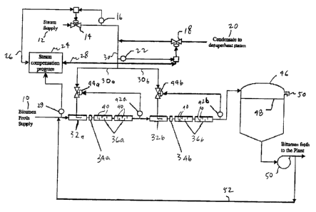
Figure 1 is a functional block diagram of a preferred embodiment of a
bitumen froth heating process arrangement of the invention.
Figure 2 is a cross section elevation view of an inline steam heater and
mixer stage of Figure 1.
CA 02455011 2004-01-09
-3-
Figure 2a is an elevation view of a baffle plate of Figure 2.
DETAILED DESCRIPTION OF THE INVENTION
In accordance with a preferred embodiment of the process two inputs
components, namely, bitumen froth and steam, are contacted to produce an
output homogenous bitumen product heated to a temperature of 190 F. The
input bitumen froth component 10 is supplied at about 150 F. In a pilot plant
implementation the input bitumen froth component is supplied via a 28 inch
pipeline at a rate of about 10,000 barrels per hour. The input steam component
12 is supplied as a superheated steam at about 500 F and at 150 psi.
Figure 1 shows a functional block diagram of a preferred embodiment of a
bitumen froth heating apparatus arranged in accordance with the invention. The
input steam component 12 is supplied to a pressure control valve 14 which
reduces the pressure to a set point pressure, which is typically about 90 psi.
A
pressure transmitter 16 is provided to monitor the pressure of the steam
downstream from the pressure control valve 14 to provide a closed loop control
mechanism to control the pressure of the steam at the set point pressure. The
pressure controlled steam is supplied to a temperature control valve 18 that
is
used to control the supply of condensate 20 to cool the steam to its
saturation
point, which is about 300 F at the controlled pressure of 90 psi. A
temperature
sensor 22 monitors the steam temperature downstream from the temperature
control valve to provide a closed loop control mechanism to control the
temperature of the steam at the temperature set point setting.
The optimum parameters for steam injection vary so a computer 24 executes a
compensation program to review the instantaneously supplied instrumentation
pressure 26 and temperature 28 measurements and adjusts inlet steam pressure
and temperature set point settings as required. A pressure sensor 29 measures
the pressure of the input bitumen component 10 to provide the compensation
program executing on computer 24 with this parameter to facilitate optimum
control of the parameters for steam injection.
40198815.2
CA 02455011 2009-10-06
-4-
To provide a greater capacity for supply or transfer of heat to the bitumen
froth component, the pressure and temperature controlled steam 30 is split
into two steam sub-streams 30a, 30b. Each steam sub-stream is supplied to a
respective steam injector 32a, 32b and the steam injectors 32a and 32b are
arranged in series to supply heat to the bitumen froth component stream 10.
While two steam injectors arranged in series are shown in the figure, it will
be
understood that the bitumen froth component stream 10 could equally well be
split into two sub-streams and each bitumen froth component sub-stream
supplied to a respective steam injector arranged in parallel. Moreover, it
will
be understood that more than two sub-streams of either the steam component
or the bitumen component streams could be provided if process flow rates
require. A suitable inline steam injector 32a, 32b is manufactured by Komax
Systems Inc. located in California, USA.
An inline steam injection heater works well in heating water compatible fluids
but bitumen is not water compatible so additional mixing is advantageous to
achieve uniform fluid temperature. Consequently, in the preferred
embodiment depicted in Figure 1, the bitumen and steam material flow
mixture is passed through an inlet baffle 34a, 34b downstream from the
respective steam injector 32a, 32b. The inlet baffle, which is shown more
clearly in Figure 2a, directs the material flow mixture downward to initiate
the
mixing action of the steam component with the bitumen froth component.
As is indicated by the arrows in Fig. 2, following the initial contact of the
steam
with the bitumen flowing in a pipeline, the two incompatible substances are
then forced through the baffle 34 and through the series of static mixers 36
causing the steam to contact the froth.
Mixing of the material flow continues by passing the material flow through
static mixers 36a and 36b respectively.
CA 02455011 2009-10-06
-4a-
As seen most clearly in Figure 2, the static mixers provide baffles 40
arranged
along the interior volume of each static mixer to effect a mixing action of
the
material flowing through the static mixer. The mixing action of the material
flow through the static mixer is provided by arranging the baffles 40 within
the
static mixer to impart a lateral, radial, tangential and/or circumferential
directional component to the material flow that changes repeatedly along the
length of the static mixer. Different static mixer designs and baffle
arrangements may be used to advantage in mixing the steam component with
the bitumen froth component.
CA 02455011 2004-01-09
-5-
A temperature transmitter 42 is located downstream of the mixers 36. The
temperature of the material flow exiting the static mixer is measured by the
temperature transmitter 42 and is used to control the rate of supply of steam
to
the inline steam injector 32 by the associated flow control valve 44. In this
manner, a closed loop control system is provided to control the supply of the
steam component to the bitumen froth component to obtain a set point or target
output temperature of the material flow leaving the static mixer 36.
Referring again to Figure 1, the heating system shown in Figure 2 is arranged
with a temperature transmitter 42a, 42b located downstream of each respective
mixer 36a, 36b. The temperature of the material exiting each static mixer is
measured by the temperature transmitter and is used to control the rate of
supply
of steam to the inline steam injectors 32a, 32b by the associated flow control
valve 44a, 44b respectively. In this manner, a closed loop control system is
provided to control the supply of the steam component to the bitumen froth
component to obtain a set point or target output temperature of the material
flow
leaving each static mixer stage 36a, 36b.
The water content of the bitumen froth component 10 can range form 30% to
50%. In a pilot plant implementation of the preferred embodiment, each inline
steam heater 32a, 32b was found to be capable of heating about 10,000 barrels
per hour of bitumen froth by about 30 F utilizing about 80,000 pounds per hour
of
steam. By way of comparison to conventional process apparatus, the
atmospheric tank method would use about 125,000 pounds of steam to achieve a
similar heat transfer.
After heating, the heated bitumen froth is delivered to a plant for
processing. To
facilitate material flow rate co-ordination with the processing plant, the
heated
bitumen froth may be discharged to a downstream holding tank 46, preferably
above the liquid level 48. The heated, mixed bitumen froth releases entrained
air,
preferably, therefore, the holding tank is provided with a vent 50 to disperse
the
entrapped air released from the bitumen froth. To maintain the temperature of
the
heated bitumen froth in the holding tank 46, a pump 50 and recycle line 52 are
40198815.2
CA 02455011 2004-01-09
-6-
provided, which operate to recycle the hot bitumen froth from the holding tank
to
the process inlet of the heaters.
The invention has been described with reference to preferred embodiments.
Those skilled in the art will perceive improvements, changes, and
modifications.
The scope of the invention including such improvements, changes and
modifications is defined by the appended claims.
40198815.2