Language selection

Search

Patent 2455133 Summary

Third-party information liability

Some of the information on this Web page has been provided by external sources. The Government of Canada is not responsible for the accuracy, reliability or currency of the information supplied by external sources. Users wishing to rely upon this information should consult directly with the source of the information. Content provided by external sources is not subject to official languages, privacy and accessibility requirements.

Claims and Abstract availability

Any discrepancies in the text and image of the Claims and Abstract are due to differing posting times. Text of the Claims and Abstract are posted:

  • At the time the application is open to public inspection;
  • At the time of issue of the patent (grant).
(12) Patent: (11) CA 2455133
(54) English Title: AUTOMATIC GARAGE DOOR CLOSING SYSTEM
(54) French Title: SYSTEME DE FERMETURE AUTOMATIQUE DE PORTE DE GARAGE
Status: Deemed expired
Bibliographic Data
(51) International Patent Classification (IPC):
  • E05F 15/70 (2015.01)
  • E05F 15/60 (2015.01)
  • H02P 1/00 (2006.01)
  • H02P 3/00 (2006.01)
  • H02P 5/00 (2006.01)
(72) Inventors :
  • GRAHAM, KENNETH B. (Canada)
  • CHAPPLE, LAWRENCE (Canada)
(73) Owners :
  • 1138668 ALBERTA LTD. (Canada)
(71) Applicants :
  • MIND-EASE GARAGE DOOR SYSTEMS LTD. (Canada)
(74) Agent: NA
(74) Associate agent: NA
(45) Issued: 2007-03-27
(22) Filed Date: 2003-05-14
(41) Open to Public Inspection: 2004-07-15
Examination requested: 2003-05-14
Availability of licence: N/A
(25) Language of filing: English

Patent Cooperation Treaty (PCT): No

(30) Application Priority Data:
Application No. Country/Territory Date
10/248,376 United States of America 2003-01-15

Abstracts

English Abstract

12 An automatic garage door closing system to be used in combination with a garage door opener. The automatic garage door closing system includes a control box, a power source and a door sensor switch. The control box includes a timer. The timer has a first predetermined time period which is set by a user and activates the garage door opener to close a garage door. The timer has a second predetermined time period which is fixed and which shuts down and resets the automatic garage door closing system. The power source is connected to the control box to activate and power the control box, including the timer of the control box. The door sensor switch senses opening of the garage door and activates the power source to activate the control box.


French Abstract

12 Un système de fermeture automatique de porte de garage pour être utilisé en combinaison avec un ouvre-porte de porte de garage. Le système de fermeture automatique de porte de garage comprend un boîtier de commande, une source d'alimentation et un interrupteur de capteur de porte. Le boîtier de commande comporte une minuterie. La minuterie comporte une première période prédéterminée qui est définie par un utilisateur et active l'ouvre-porte de la porte de garage pour fermer une porte de garage. La minuterie a une deuxième durée prédéterminée qui est fixe et qui arrête et réinitialise le système de fermeture automatique de la porte de garage. La source d'alimentation est connectée au boîtier de commande pour activer et alimenter le boîtier de commande, y compris la minuterie du boîtier de commande. L'interrupteur de capteurs de porte capte l'ouverture de la porte de garage et active la source d'alimentation pour activer le boîtier de commande.

Claims

Note: Claims are shown in the official language in which they were submitted.


page 6
CLAIMS

I Claim:

1. An automatic garage door closing system to be used in combination with a
garage
door opener, comprising:
a control box, said control box including a timer, said timer having a first
predetermined time period which is set by a user and activates said garage
door
opener to close a garage door after said first predetermined time period has
ended,
said timer having a second predetermined time period which is fixed, and said
timer discontinues activation of said garage door opener and resets said
automatic
garage door closing system after said second predetermined time period has
ended;
a power source connected to said control box to activate and power said
control
box including said timer of said control box;
a light as part of said control box and connected to components of said
control
box to indicate power source status and that said control box is functioning
during
said first and second predetermined time periods; and
a door sensor switch, said door sensor sensing opening of said garage door and
activates said power source to activate said control box and said door sensor


page 7

sensing closing of said garage door and deactivates said power source to
deactivate said control box.

2. The automatic garage door closing system of claim 1, wherein said power
source
is a battery located in said control box.

3. The automatic garage door closing system of claim 1, wherein the light is
an LED
light.

4. The automatic garage door closing system of claim 1, further including an
external ON/OFF switch to activate and deactivate said power source from said
control box.

5. The automatic garage door closing system of claim 1, wherein said timer is
a
combination of a microprocessor and a potentiometer connected together,
wherein
microprocessor is programmed to countdown said first and second predetermined
time periods; wherein said microprocessor is programmed to activate and
deactivate said garage door opener; and wherein said potentiometer is
connected
to said microprocessor to be set be said user to determine said first
predetermined
time period.

6. The automatic garage door closing system of claim 5, wherein said
potentiometer
includes an external moving control along a time indication scale, said moving


page 8


control connected to said potentiometer to control amount of time of said
first
predetermined time period.

7. The automatic garage door closing system of claim 1, wherein said first
predetermined time period is between five minutes and one hour.

8. The automatic garage door closing system of claim 1, wherein said second
predetermined time period is five-hundred milliseconds.

9. The automatic garage door closing system of claim 7, wherein said second
predetermined time period is five-hundred milliseconds.

10. The automatic garage door closing system of claim 1, wherein said control
box
includes a relay; wherein said relay is activated by said timer after said
first
predetermined time period has ended; wherein said relay activates a push
button
box in response to activation by said timer; wherein said push button is
connected
to said garage door opener and commands said garage door opener to close said
garage door in response to activation by said relay; and wherein said timer
deactivates said relay after said second predetermined time period has ended
which also deactivates said push button box.

11. The automatic garage door closing system of claim 5, wherein said control
box
includes relay switching device and a relay; wherein said relay switching
device is


page 9


activated at an end of said first predetermined time period by said
microprocessor;
wherein activation of said relay switching device activates said relay;
wherein
activation of said relay activates a push button box which is connected to
said
garage door opener and which commands said garage door opener to close said
garage door, and wherein said microprocessor deactivates said relay switching
device after said second predetermined time period has ended which also
deactivates said relay and said push button box.

12. The automatic garage door closing system of claim 1, wherein said power
source
is a battery located in said control box; wherein said timer is a combination
of a
microprocessor and a potentiometer connected together; wherein said
microprocessor is programmed to countdown said first and second predetermined
time periods; wherein said microprocessor is programmed to activate and
deactivate said garage door opener, and wherein said potentiometer is
connected
to said microprocessor to be set by said user to determine said first
predetermined
tine period; and wherein said potentiometer includes an external moving
control
along a time indication scale, said moving control connected to said
potentiometer
to control amount of time of said first predetermined time period.

13. The automatic garage door closing system of claim 12, further including an
external ON/OFF switch to activate and deactivate said power source from said
control box.


page 10


14. The automatic garage door closing system of claim 12, further including an
external ON/OFF switch to activate and deactivate said power source from said
control box and wherein the light is an LED light.

15. The automatic garage door closing system of claim 12, wherein said first
predetermined time period is between five minutes and one hour; and wherein
said second predetermined time period is five-hundred milliseconds.

16. The automatic garage door closing system of claim 14, wherein said first
predetermined time period is between five minutes and one hour, and wherein
said second predetermined time period is five-hundred milliseconds.

17. The automatic garage door closing system of claim 16, wherein said door
sensor
switch is a micro switch.

18. The automatic garage door closing system of claim 16, wherein said door
sensor
switch is a magnetic switch.

19. The automatic garage door closing system of claim 15, wherein said control
box
includes a relay switching device and a relay; wherein said relay switching
device
is activated at an end of said first predetermined time period by said
microprocessor; wherein activation of said relay switching device activates
said
relay; wherein activation of said relay activates a push button box which is


page 11


connected to said garage door opener and which commands said garage door
opener to close said garage door; and wherein said microprocessor deactivates
said relay switching device after said second predetermined time period has
ended
which also deactivates said relay and said push button box.

20. An automatic garage door closing system kit to be added to a garage door
opener,
comprising:
a control box, said control box including a timer, said timer having a first
predetermined time period which is set by a user and activates said garage
door
opener to close a garage door after said first predetermined time period has
ended,
said timer having a second predetermined time period which is fixed, and said
timer discontinues activation of said garage door opener and resets said
automatic
garage door closing system after said second predetermined time period has
ended;
a power source connected to said control box to activate and power said
control
box, including said timer of said control box;
a light as part of said control box and connected to components of said
control
box to indicate power source status and that said control box is functioning
during
said first and second predetermined time periods;


page 12


a door sensor switch, said door sensor sensing opening of said garage door and
activates said power source to activate said control box and said door sensor
sensing closing of said garage door and deactivates said power source to
deactivate said control box; and
a replacement pushbutton box to replace an existing pushbutton box of said
garage door opener, said replacement pushbutton box connected to said control
box and connected to said garage door opener, such that said control box
commands said garage door opener to close said garage door after said first
predetermined time period has ended.

21. The automatic garage door closing system kit of claim 20, wherein said
power
source is a battery located in said control box; wherein said timer is a
combination
of a microprocessor and a potentiometer connected together, wherein said
microprocessor is programmed to countdown said first and second predetermined
time periods; wherein said microprocessor is programmed to activate and
deactivate said garage door opener; wherein said potentiometer is connected to
said microprocessor to be set be said user to determine said first
predetermined
time period; wherein said potentiometer includes an external moving control
along a time indication scale, said moving control connected to said
potentiometer
to control amount of time of said first predetermined time period; wherein
said
control box includes a relay; wherein said relay is activated by said
microprocessor after said first predetermined time period has ended; wherein
said


page 13

relay activates said replacement push button box in response to activation by
said
microprocessor; wherein said replacement push button is connected to said
garage
door opener and commands said garage door opener to close said garage door in
response to activation by said relay; and wherein said microprocessor
deactivates
said relay after said second predetermined time period has ended which also
deactivates said replacement push button box.

22. The automatic garage door closing system kit of claim 21, further
including an
external ON/OFF switch to activate and deactivate said power source from said
control box.

23. The automatic garage door closing system kit of claim 20, wherein the
light is an
LED light.


Description

Note: Descriptions are shown in the official language in which they were submitted.


CA 02455133 2003-05-14
1
AUTOMATIC GARAGE DOOR CLOSING SYSTEM
BACKGROUND
S
The present invention generally relates to garage door systems. More
specifically, the present invention relates to an automatic garage door
closing system
which can be added t.o an existing garage door system.
There are garage door systems available with an automatic closing feature.
Unfortunately. most of these systems do zzot appear to be systen as which can
be easily
added to an existing garage door system of the common variety. The current
systems can
prove difficult for the average home owner to install. Those systems ~.vhich
caza be
installed by home owner, lack simplicity of use.
1S
It is an object of the present invention to provide an automatic garage door
closing
system which can be added to an existing garage door systerza.
2U
SUMMARY OF 1'H)E TN'VENTION
An automatic garage door closing system to be used in combination with a
garage
door opener. The automatic garage door closing system includes a control box,
a power
source and a di)Ur sensor switch. The control box includes a timer. The
tiixz.er has a first
25 predetem~ined time period which is set by a user and activates the garage
door opener to
close a garage door. Tf~e timer has a second predetermined time period which
is fixed
and which shuts down arzd resets the automatic garage door closing system. The
power
source is cozmeeted to the control box to activate and power the control box.
including,
the timer of the control box. The door sensor switch senses opening of the
garage door
30 and activates the power source to activate tlLC control box.

CA 02455133 2003-05-14
2
BRIEF DESCRIPx'XON QE DItAWINCS
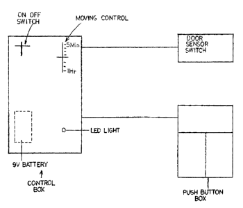
Fig. 1 is a schematic view of componexwts of an automatic garage door closing
system according to the present invention; and
Fig. 2 is a schematic vices of an example of cizcuitry that can be used with
the
automatic garage door closing systezxx according to the present invention.
DETAILED DESC~1:~~''.TQN
The present invention is an automatic garage door closing system, as shown in
Figs. 1-2. Fig. 1 shows a schematic of the components that make up the
automatic garage
door closing system. Fig. 2 shows a schematic of an example of the circuitry
that can be
used with the automatic garage door closing systezxa. The automatic garage
door closing
system is shown wired to an existixag push button box that is part of an
existing garage
door switch in a garage door opener. The automatic garage door closing system
includes
a power source, door sensor switch and a control box. The power source is
linked to the
control box to power the automatic garage door closing system. The door sensor
switch
is connected to the control box and mounted near the garage door to sense the
opening
and closing movement of the garage dour. The door sensor switch can be a
magnetic
switch, micro-switch or other similar device. Part of the door sensor switch
can actually
mounted on the garage door, as such would be the case with a magnetic switch.
The
control box is mounted in a convenient location in the garage, where it can be
easily
accessed by a user.
The control box is the brains of the automatic garage door closinb system. The
power source is shown within the control box as a nine Volt (9V) battery. The
control
box includes an ONIOFF switch, timer, hhla light, relay sw:itchin~~ device and
relay. The

CA 02455133 2003-05-14
3
ONIOFF switch interrupts the power source in order to turn the automatic
garage door
closing system on and off. The ON/OFF switch includes a toggle lever external
to the
control box. The timer is comprised of a microprocessor azxd a
potentiozxxeter. The
potentiometer includes a moving control e.~cternal to the control box. The
microprocessor
is programmed to countdown a first predetermined time period, depending on the
position of the moving control of the potentiometer. The microprocessor
includes an
output to power the LED light. The microprocessor is connected to the door
sensor
switch. The microprocessor is also programmed to perform a countdown of a
second
predetermined time period. The relay switching device is shown as Metal Dxide
Semiconductor Field Effect Transistor (MOSFET). The switching device is used
to
switch the relay on and off when cozrzmmanded by the microprocessor. The relay
is
connected to the existing garage door switch of a garage door opener, where in
the case
of Figs. 1-2, the relay is shown connected to a push button box.
The operation of the automatic garage door closing system is as follows. The
garage door is opened by activating the existing garage door switch of the
garage door
opener by using the push button box wired to tlxe garage door opener or a
wireless push
button device (not shown). During opening movement of the garage door, the
door
sensor switch will be activated and be switched to a closed position. When the
door
sensor switch closes, the microprocessor is powered by the power source. The
ONIOFF
switch of the control box anust be in the ON position to allow the
microprocessor to be
powered by the power source. If the ONIOFF switch is in the OFF, position the
microprocessor will not be powered and the garage door will remain open. The
control
box includes an time indication scale of time next to the movinfi control of
the
2~ potentiometer. Typical tizxxe settings are between five minutes to one
hour. Whereby, the
position of tlxc moving control along the time indication scale is also a
position of the
moving control along a wiper of the potentiometer. The moving control can be a
sliding
lever or a rotating knob. When the zxxicroprocessar is powered, the
mic,~roprocessar reads
the voltage level on the wipv~r of the potentiometer and izzterprets this
voltage level as a
time period, as indicated by the sliding lever along the time indication
scale. This

CA 02455133 2003-05-14
4
interpretation of a time period in relation to voltage level is due to the
programming of
the microprocessor. The microprocessor then begins a countdown of the first
predetermined time period, as set by the moving control. At the erzd of the
first
predetez-zztizted tizxze period, tb.e z"icroprocessor outputs a logic T~xgh
~xve volt (5V) to a
gate of the relay switching device, which tuxrzs on the relay by closing the
relay.
Activation of the relay shorts together the terminals of the existing push
button box that is
wired to the garage door opezier_ The shortiztg of the terzxzinals of the
existing push
button box activates a cozTtntand it, the garage door opener to close the
garage door.
When the relay is turned on, the n,ieroprocessor begins a countdown of the
second
predetermined time period of five-hundred milliseconds. After the countdown
ot~ the
second predetermined time period, the microprocessor turns off the relay by
opening the
relay, which removes the short from the terminals of the existing push button
box. As the
garage door passes the door sensor switch while closing, the door sensor
switch is again
activated due to door movement and opens the door sensor switch. Opening of
tlc door
sensor switch rerztoves the power front the ztticroprocessor, ceases
operation. of the
microprocessor and resets the automatic garage doox closing System_ The
z,ticroprocessor
will only be restarted by the opening of' the garage door. Between the period
of powering
of the microprocessor and removal of power to the microprocessor, the output
to power
the LED light causes the LED light to blink periodically to indicate the
battery for the
power source is adequate and the automatic garage door closing systc.~rz is
functioning.
The blinking of the LED light aJtd moztitoring of the power source and the
system are all
part of the progarnming of the microprocessor.
Tlzc fO110~V1IIg are alternatives which can be added to the above-mentioned
embodiment. Instead of cozutecting the relay to the existing push button box
of the
garage door opener, the relay could be directly connected to the garage door
opener to
close the garage door. The connecting of the relay to the existing push button
bo:c of the
garage door opener provides a simpler installation for tlla home owner.
Whereby, a
replacement push button box with the proper cozzn.ections to the control box
aztd existing
garage door opener could be provided as part of a kit to replace the existing
push button

CA 02455133 2003-05-14
box. Finally, the power source could be a direct .A,C electrical power source,
possibly
from the garage door opener itself.
'VVh.ile different embodiments of the invention have been described in detail
5 herein, it will be appreciated by those slcillcd in the art that various
modifications and
alternatives to the embodiments could be developed in light of the overall
teachings of
the disclosure. Accordingly, the particular arrangements are illustrative only
and are not
limiting as to the scope of the invention that is to be given the full breadth
of any and all
equivalents thereof.

Representative Drawing
A single figure which represents the drawing illustrating the invention.
Administrative Status

For a clearer understanding of the status of the application/patent presented on this page, the site Disclaimer , as well as the definitions for Patent , Administrative Status , Maintenance Fee  and Payment History  should be consulted.

Administrative Status

Title Date
Forecasted Issue Date 2007-03-27
(22) Filed 2003-05-14
Examination Requested 2003-05-14
(41) Open to Public Inspection 2004-07-15
(45) Issued 2007-03-27
Deemed Expired 2017-05-15

Abandonment History

There is no abandonment history.

Payment History

Fee Type Anniversary Year Due Date Amount Paid Paid Date
Request for Examination $200.00 2003-05-14
Registration of a document - section 124 $100.00 2003-05-14
Application Fee $150.00 2003-05-14
Maintenance Fee - Application - New Act 2 2005-05-16 $50.00 2005-04-13
Registration of a document - section 124 $100.00 2006-01-06
Maintenance Fee - Application - New Act 3 2006-05-15 $50.00 2006-03-17
Final Fee $150.00 2007-01-05
Maintenance Fee - Patent - New Act 4 2007-05-14 $50.00 2007-03-29
Maintenance Fee - Patent - New Act 5 2008-05-14 $100.00 2008-04-18
Maintenance Fee - Patent - New Act 6 2009-05-14 $100.00 2009-04-14
Maintenance Fee - Patent - New Act 7 2010-05-14 $100.00 2010-04-06
Maintenance Fee - Patent - New Act 8 2011-05-16 $100.00 2011-04-06
Maintenance Fee - Patent - New Act 9 2012-05-14 $100.00 2012-04-11
Maintenance Fee - Patent - New Act 10 2013-05-14 $125.00 2013-04-04
Maintenance Fee - Patent - New Act 11 2014-05-14 $125.00 2014-04-11
Maintenance Fee - Patent - New Act 12 2015-05-14 $125.00 2015-03-27
Owners on Record

Note: Records showing the ownership history in alphabetical order.

Current Owners on Record
1138668 ALBERTA LTD.
Past Owners on Record
CHAPPLE, LAWRENCE
GRAHAM, KENNETH B.
MIND-EASE GARAGE DOOR SYSTEMS LTD.
Past Owners that do not appear in the "Owners on Record" listing will appear in other documentation within the application.
Documents

To view selected files, please enter reCAPTCHA code :


To view images, click a link in the Document Description column. To download the documents, select one or more checkboxes in the first column and then click the "Download Selected in PDF format (Zip Archive)" or the "Download Selected as Single PDF" button.

List of published and non-published patent-specific documents on the CPD .

If you have any difficulty accessing content, you can call the Client Service Centre at 1-866-997-1936 or send them an e-mail at CIPO Client Service Centre.


Document
Description 
Date
(yyyy-mm-dd) 
Number of pages   Size of Image (KB) 
Description 2003-05-14 5 199
Abstract 2003-05-14 1 18
Claims 2003-05-14 6 228
Drawings 2003-05-14 2 31
Representative Drawing 2004-04-16 1 6
Cover Page 2004-06-21 1 36
Claims 2006-02-06 8 220
Cover Page 2007-03-08 1 38
Assignment 2003-05-14 9 240
Fees 2005-04-13 3 66
Prosecution-Amendment 2006-02-06 12 397
Prosecution-Amendment 2005-08-15 2 87
Assignment 2006-01-06 7 135
Assignment 2006-01-06 7 131
Fees 2006-03-17 3 70
Correspondence 2007-01-05 2 66
Fees 2007-03-29 4 118
Fees 2008-04-18 1 26
Fees 2009-04-14 1 32
Fees 2010-04-06 1 26
Fees 2011-04-06 1 24
Fees 2012-04-11 1 24
Fees 2013-04-04 1 24
Fees 2014-04-11 1 24
Fees 2015-03-27 1 25
Office Letter 2016-06-10 1 33