Language selection

Search

Patent 2455239 Summary

Third-party information liability

Some of the information on this Web page has been provided by external sources. The Government of Canada is not responsible for the accuracy, reliability or currency of the information supplied by external sources. Users wishing to rely upon this information should consult directly with the source of the information. Content provided by external sources is not subject to official languages, privacy and accessibility requirements.

Claims and Abstract availability

Any discrepancies in the text and image of the Claims and Abstract are due to differing posting times. Text of the Claims and Abstract are posted:

  • At the time the application is open to public inspection;
  • At the time of issue of the patent (grant).
(12) Patent: (11) CA 2455239
(54) English Title: SAND SEPARATION VESSEL
(54) French Title: RECIPIENT POUR LA SEPARATION DU SABLE
Status: Term Expired - Post Grant Beyond Limit
Bibliographic Data
(51) International Patent Classification (IPC):
  • B03B 9/02 (2006.01)
  • B01D 21/00 (2006.01)
(72) Inventors :
  • PAGE, PAT (Canada)
  • PAGE, COLIN (Canada)
(73) Owners :
  • PAT PAGE
  • JACK MONKMAN
(71) Applicants :
  • PAT PAGE (Canada)
  • JACK MONKMAN (Canada)
(74) Agent: BENNETT JONES LLP
(74) Associate agent:
(45) Issued: 2011-04-12
(22) Filed Date: 2004-01-15
(41) Open to Public Inspection: 2005-07-15
Examination requested: 2008-01-22
Availability of licence: N/A
Dedicated to the Public: N/A
(25) Language of filing: English

Patent Cooperation Treaty (PCT): No

(30) Application Priority Data: None

Abstracts

English Abstract

A vessel for separating sand and other solid particulate matter from heavy oil and other hydrocarbons includes a horizontally disposed vessel having a plurality of internal weirs. There are gaps below the weirs along the bottom of the vessel where wash jets provide fluid force to move the sand along the bottom of the vessel and provide agitation. The wash fluid may comprise known surfactants or solvents. The solids may be introduced into the vessel at a first end and collected from a solids outlet at a second end. Oil may be skimmed from the top of the vessel with an oil outlet or skimmer.


French Abstract

Un récipient permettant de séparer du sable et d'autres matières particulaires solides de pétrole lourd et d'autres hydrocarbures comprenant un récipient disposé horizontalement muni de plusieurs déversoirs. Des espaces sont placés sous les déversoirs le long de la partie inférieure du récipient où des jets de lavage fournissent une force de fluide pour déplacer le sable le long de la partie inférieure du récipient et fournir un brassage. Le fluide de lavage peut comprendre un solvant ou des agents de surface connus. Les solides peuvent être introduits dans le récipient à une première extrémité et rassemblés d'une sortie de solides à une deuxième extrémité. Le pétrole peut être écumé à partir de l'extrémité supérieure du récipient avec une sortie de pétrole ou une écumoire.

Claims

Note: Claims are shown in the official language in which they were submitted.

WHAT IS CLAIMED IS:
1. A separation vessel comprising:
(a) an elongate vessel having a first end and a second end, a bottom portion,
and a
longitudinal axis passing through the first and second ends;
(b) at least one internal weir transversely disposed within the vessel and
having a top
edge and a bottom edge, wherein a gap is maintained between the bottom edge of
the weir and the vessel;
(c) a plurality of jets disposed along the bottom portion of the vessel and
aimed
substantially towards the second end of the vessel;
(d) means for pressurizing a wash fluid and directing the fluid through the
jets into
the vessel;
(d) a feedstock inlet associated with the first end of the vessel; and
(e) a fluid outlet defined by the vessel, substantially level with or higher
than the
height of the top edge of an internal weir, and
(f) a solids outlet defined by the vessel towards the second end of the
vessel.
2. The vessel of claim 1 wherein the fluid outlet is located at the first end
of the vessel.
3. The vessel of claim 1 wherein the plurality of jets are arranged such that
a plurality of jet
arrays are provided along the length of the vessel, wherein each jet array
comprises at least two
jets aligned transverse to the longitudinal axis.
4. The vessel of claim 3 wherein the solids outlet is located at the second
end of the vessel.
5. The vessel of claim 1 wherein the at least one internal weir comprises a
plurality of
internal weirs.
-7-

6. The vessel of claim 1 wherein the at least one internal weir is adjustable
to vary the height
of the internal weir within the vessel.
-8-

Description

Note: Descriptions are shown in the official language in which they were submitted.


CA 02455239 2004-01-15
CA PATENT
File No. 49919.3
SAND SEPARATION VESSEL
FIELD OF THE INVENTION
The present invention relates to a vessel for separating particulate matter
and
hydrocarbons. In particular, the vessel may be used for separating sand
contaminated with heavy
oil or bitumen.
BACKGROUND OF THE INVENTION
Heavy oil is often produced along with large amounts of sand and water.
Primary
separation of the oil, sand and water mixture takes place in field storage
tanks, where the sand
and other solid particulate matter sinks to the bottom, while the oil floats
to the top. The oil is
removed periodically while the sand and water are also periodically cleaned
from the tank. As
may be appreciated, there is usually a significant amount of oil contaminating
the solids removed
from storage tanks. This contamination complicates the disposal of such
produced solids.
The separation and disposal of produced sand from heavy oil well production is
a major
production and environmental problem in the heavy oil producing areas, such as
certain areas of
Western Canada. Currently, the two most common means of handling produced sand
involves
the trucking and injection of produced solids into specialized disposal wells,
or by landfarming
the product. An alternative method for dealing with the produced sand involves
using the
product in road construction. However, there are environmental and regulatory
issues involved
with both landfarming and reuse in road construction.
Therefore, there is a need in the art for an economical and environmentally
sound method
of treating sand which is contaminated with oil.

CA 02455239 2004-01-15
SUMMARY OF THE INVENTION
The present invention provides a separation vessel for treating sand and other
particulate
matter contaminated with heavy oil and other hydrocarbons. In one aspect, the
invention may
comprise a separation vessel comprising:
(a) an elongate vessel having a first end and a second end, a bottom portion,
and a
longitudinal axis passing through the first and second ends;
(b) at least one internal weir transversely disposed within the vessel and
having a top
edge and a bottom edge, wherein a gap is maintained between the bottom edge of
the weir and the vessel;
(c) a plurality of j ets disposed along the bottom portion of the vessel wall
and aimed
substantially towards the second end of the vessel;
(d) means for pressurizing a wash fluid and directing the fluid through the
jets into
the vessel;
(d) a feedstock inlet associated with the first end of the vessel; and
(e) a fluid outlet defined by the vessel, substantially level with or higher
than the
height of the top edge of an internal weir, and
(f) a solids outlet defined by the vessel towards the second end of the
vessel.
BRIEF DESCRIPTION OF THE DRAWINGS
The invention will now be described by way of an exemplary embodiment with
reference
to the accompanying simplified, diagrammatic, not-to-scale drawings. In the
drawings:
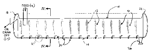
Figure 1 is a side view of one embodiment of the present invention.
Figure 2 is a top plan view of the embodiment of Figure 1.
Figure 3 is a cross-sectional view along line III in Figure 2.
-2-

CA 02455239 2004-01-15
Figure 4 is a cross-sectional view along line IV in Figure 1.
Figure 5 is a detailed view of one embodiment of a jet used in the present
invention.
Figure 6 is a schematic representation of the sand/liquid separation cyclone
and wash
fluid recovery system.
DETAILED DESCRIPTION OF THE INVENTION
The present invention provides for a separation vessel. When describing the
present
invention, all terms not defined herein have their common art-recognized
meanings. The vessel
is intended to receive sand, or other solid particulate material, which is
contaminated with heavy
oil, or other hydrocarbons. Through the use of a wash fluid which may comprise
a solvent or
surfactant, or combinations thereof, the oil is separated from the sand and
removed. The sand is
cleaned and recovered.
One embodiment of a vessel of the present invention is shown in Figure 1. The
vessel is
an elongated vessel (10) which may be, but not necessarily, cylindrical. The
interior of the vessel
is divided by a plurality of transverse weirs (12) which are attached to the
interior sidewall of the
vessel (10) as shown in Figures 2 and 4. The weirs (12) have a defined height,
which may be
adjustable, and may leave a gap between the bottom of the weir, and the bottom
(14) of the
vessel. The bottom gap maybe adjustable.
Contaminated sand is introduced into the vessel through the feedstock intake
(16), which
is provided at a first end (18) of the vessel. A plurality of wash jets (20)
are provided along the
bottom (14) of the vessel, below the bottom level of the weirs (12), as is
shown in Figure 1 and 4.
The wash jets (20) introduce a wash fluid into the vessel, agitate the sand
which has settled to
the bottom of the vessel, and push the sand towards the second end (22) of the
vessel.
The vessel may be closed or it may have a top portion removed for easy
physical and
visual access to the vessel interior, as is shown in Figures 1 and 2.
-3-

CA 02455239 2004-01-15
As shown in Figure 3, the feedstock intake (16) may be a hopper or trough
which delivers
the contaminated sand to the vessel. The feedstock may preferably be an
aqueous slurry of
contaminated sand.
As may be seen in Figure 4, in one embodiment, each internal weir (12) may be
comprised of a plurality of plates, to permit height adjustability. Clip
plates (12A) may be
welded to the sidewall of the vessel. An intermediate plate (12B) may be
bolted to the clip plates
and movable in vertical direction to control the top edge height of the weir
(12). A third plate
(12C) may be provided and bolted to the intermediate plate (12B), or the clip
plates (12A), and
movable in a vertical direction to control the clearance height of the bottom
edge of the weir.
Also shown in Figure 4, the wash jets (20) may be arrayed in rows along the
bottom
portion of the vessel. In one embodiment, a number of jets are provided along
a line which is
transverse to the longitudinal axis of the vessel. The spacing between
adjacent jets maybe
variable. In one embodiment, one jet is provided every 15 of arc along the
bottom of the vessel,
with a total of 5 jets in one row. The rows of wash jets maybe substantially
aligned with the
internal weirs and therefore, there may be as many rows of wash jets as there
are internal weirs.
Upon activation of the wash jets, some circulation will likely occur within
each cell created
between two weirs (12). Accordingly, the length of the vessel and the number
of weirs are
important factors in determining the efficacy of the washing action. At a bare
minimum, a single
weir would create two compartments. The maximum number of weirs is limited
only by the
length of the vessel and complexity of fabrication. It is preferable to
provide enough spacing
between the weirs that some recirculation of the solids and wash fluids takes
place.
In one embodiment, as shown in the Figures, 15 weirs are provided and spaced
such that
the distance between adjacent weirs is approximately one-third the diameter of
the vessel.
Each wash jet (20) may be conveniently fabricated from conventional pipe
fittings as
shown in Figure 5 where a wash jet fabricated from standard 90 elbow fittings
is shown. The jet
outlet (13) maybe restricted to increase the velocity of the fluid flowing
from the wash jet.
-4-

CA 02455239 2010-09-07
The wash fluid may be a surfactant or a solvent, or mixtures thereof, known to
remove oil
from sand. Preferably, the wash fluid is a surfactant mixed in water. In one
embodiment, the
wash fluid comprises the surfactant described in Applicant's co-pending U.S.
Patent Application
No. 10/604,076 filed on June 25, 2003 (corresponding to Canadian Patent
Application
2,433,522).
The action of the wash fluid jetted into the vessel (10) scrubs the sand,
lifts the oil and
pushes the sand towards the second end (22) of the vessel. If the vessel is of
sufficient length, by
the time the sand has reached the solids outlet, which is located at the
second end, it is relatively
free of oil. The oil which has separated from the sand will float to the top
of the vessel, between
the weirs (12). Provided that the fluid level in the vessel is high enough,
the oil will float on the
surface, above the level of the weirs. The weirs (12) act to substantially
prevent recirculation of
solids and fluids within the vessel from the second end (22) to the first
(feed intake) end (18).
When sufficient oil has been separated, it may be removed by skimming the oil
with an oil
skimmer or draw off (24). Preferably, the oil draw off (24) is substantially
level with or above
the top of the weirs (12).
As shown in Figure 6, clean sand may be removed from the vessel from the
solids outlet
(26) by conventional means. The sand will be contained in a fluid slurry. The
slurry may be
transported to a hydrocyclone (28), or other separating device, to separate
the liquids and the
solids. The liquids may be returned to a wash fluid makeup tank (30) where it
may be reused by
returning to the vessel through the wash jets.
In one embodiment, the vessel (10) is intended to be used in a partial batch
mode. The
vessel may be partially filled with the desired wash fluid and the oil-
contaminated sand deposited
through the feed inlet (16). The wash jets (20) may then be activated to wash
and agitate the
sand as it is being fed into the vessel and to push the sand towards the
second end of the vessel.
It is preferable to limit the addition of wash fluid through the wash jets so
that the level of the
wash fluid does not rise above the level of the oil draw off (24). Once clean
sand has
-5-

CA 02455239 2004-01-15
accumulated at the second end, they may be removed in a wash fluid slurry. New
feedstock and
additional wash fluid may then be added and the agitation process continued.
The oil recovered from the oil draw off (24) may be treated in a hydrocyclone
(not
shown) to assist in the removal of any entrained wash fluid or water and solid
fine material.
As will be apparent to those skilled in the art, various modifications,
adaptations and
variations of the foregoing specific disclosure can be made without departing
from the scope of
the invention claimed herein. The various features and elements of the
described invention may
be combined in a manner different from the combinations described or claimed
herein, without
departing from the scope of the invention.
-6-

Representative Drawing
A single figure which represents the drawing illustrating the invention.
Administrative Status

2024-08-01:As part of the Next Generation Patents (NGP) transition, the Canadian Patents Database (CPD) now contains a more detailed Event History, which replicates the Event Log of our new back-office solution.

Please note that "Inactive:" events refers to events no longer in use in our new back-office solution.

For a clearer understanding of the status of the application/patent presented on this page, the site Disclaimer , as well as the definitions for Patent , Event History , Maintenance Fee  and Payment History  should be consulted.

Event History

Description Date
Inactive: Expired (new Act pat) 2024-01-15
Letter Sent 2023-07-17
Letter Sent 2023-01-16
Common Representative Appointed 2019-10-30
Grant by Issuance 2011-04-12
Inactive: Cover page published 2011-04-11
Pre-grant 2011-01-31
Inactive: Final fee received 2011-01-31
Notice of Allowance is Issued 2010-12-22
Letter Sent 2010-12-22
Notice of Allowance is Issued 2010-12-22
Inactive: Approved for allowance (AFA) 2010-12-10
Amendment Received - Voluntary Amendment 2010-09-07
Inactive: S.30(2) Rules - Examiner requisition 2010-03-04
Inactive: S.29 Rules - Examiner requisition 2010-03-04
Letter Sent 2008-03-19
Request for Examination Received 2008-01-22
Request for Examination Requirements Determined Compliant 2008-01-22
All Requirements for Examination Determined Compliant 2008-01-22
Inactive: Office letter 2006-10-11
Inactive: Corrective payment - s.78.6 Act 2006-09-29
Inactive: Entity size changed 2005-11-01
Application Published (Open to Public Inspection) 2005-07-15
Inactive: Cover page published 2005-07-14
Letter Sent 2004-04-16
Inactive: IPC assigned 2004-04-07
Inactive: First IPC assigned 2004-04-07
Inactive: Single transfer 2004-03-15
Inactive: Courtesy letter - Evidence 2004-03-02
Inactive: Filing certificate - No RFE (English) 2004-02-25
Filing Requirements Determined Compliant 2004-02-25
Application Received - Regular National 2004-02-25

Abandonment History

There is no abandonment history.

Maintenance Fee

The last payment was received on 2010-11-15

Note : If the full payment has not been received on or before the date indicated, a further fee may be required which may be one of the following

  • the reinstatement fee;
  • the late payment fee; or
  • additional fee to reverse deemed expiry.

Please refer to the CIPO Patent Fees web page to see all current fee amounts.

Owners on Record

Note: Records showing the ownership history in alphabetical order.

Current Owners on Record
PAT PAGE
JACK MONKMAN
Past Owners on Record
COLIN PAGE
Past Owners that do not appear in the "Owners on Record" listing will appear in other documentation within the application.
Documents

To view selected files, please enter reCAPTCHA code :


To view images, click a link in the Document Description column. To download the documents, select one or more checkboxes in the first column and then click the "Download Selected in PDF format (Zip Archive)" or the "Download Selected as Single PDF" button.

List of published and non-published patent-specific documents on the CPD .

If you have any difficulty accessing content, you can call the Client Service Centre at 1-866-997-1936 or send them an e-mail at CIPO Client Service Centre.


Document
Description 
Date
(yyyy-mm-dd) 
Number of pages   Size of Image (KB) 
Description 2004-01-15 6 238
Abstract 2004-01-15 1 15
Claims 2004-01-15 2 37
Drawings 2004-01-15 3 39
Representative drawing 2005-06-17 1 10
Cover Page 2005-06-29 1 36
Description 2010-09-07 6 239
Claims 2010-09-07 2 38
Cover Page 2011-03-11 1 36
Filing Certificate (English) 2004-02-25 1 160
Courtesy - Certificate of registration (related document(s)) 2004-04-16 1 105
Reminder of maintenance fee due 2005-09-19 1 110
Acknowledgement of Request for Examination 2008-03-19 1 177
Commissioner's Notice - Application Found Allowable 2010-12-22 1 164
Commissioner's Notice - Maintenance Fee for a Patent Not Paid 2023-02-27 1 541
Courtesy - Patent Term Deemed Expired 2023-08-28 1 536
Fees 2011-12-22 1 155
Fees 2013-01-04 1 155
Correspondence 2004-02-25 1 25
Fees 2005-11-01 2 54
Correspondence 2006-10-11 1 15
Fees 2006-09-28 1 27
Fees 2007-12-11 1 27
Fees 2008-11-14 1 32
Fees 2009-11-19 1 199
Fees 2010-11-15 1 199
Correspondence 2011-01-31 1 24
Fees 2014-01-14 1 23
Fees 2015-01-09 1 24
Fees 2017-01-09 1 24
Maintenance fee payment 2018-01-04 1 24
Maintenance fee payment 2019-01-15 1 24