Note: Descriptions are shown in the official language in which they were submitted.
CA 02455263 2003-12-16
EPC~-~cs~"-c~..l~l
W0218W0 ~ 2 '0~3- ~~Q
7.
CQNTAINER AND CLOSURE CAP
The present invention relates to a container and
closure cap and in particular to a container having a
child resistant closure cap.
Child resistant container caps for disinfectant
containers and the like are often of the well known
squeeze-and-turn type in which the cap has a skirt which
must be squeezed at two diametrically opposite points to
disengage stops which are formed on the skirt and the
container to permit rotation of the cap for removal.
This type of cap can be manufactured simply and cheaply
because they can be moulded as a one-piece construction.
Child resistant caps for pharmaceuticals often use
an arrangement in which a cap must be pushed downwardly
to permit removal.. These arrangements are generally
rather complicated and consequently expensive to
manufacture. Caps which can be operated by pushing down
rather than by being squeezed are preferred by the
elderly, however, who find the squeezing action more
awkward.
Many push-and-turn caps use an inner cap which
closes the container~and an outer cap which must be
pushed down to engage the inner cap before the caps are
then unscrewed together. However, the use of two caps
necessitates an assembly step in production and generally
increases the complexity of the design.
Document US 3,830,391 describes a one--piece closure
and a container, in which the closure has inner and outer
walls joined by a resilient bridge. The outer wall ha,s
locking lugs which engage stop members on the container.
In order for the lugs to pass the stop members the outer
.""Y_,.,.::::>>_::.:>::,:::;,,:>:A:::.:: ~<::.. u:,..:,:~, ~,...>.,
<::;
:~:~:;.':,.:::::'.~.;".:':'..."'::.,::..,::>.~~,.~~,:::,_;.:~::i';:":x~:::F.:'.
z:
~:~:_ ;
..... . ..:::.. ~.:«a'......::.""'..:~: ~,.;;::;;";~:: w,;~ w~~';z:
...,.::....:..:....::......... .. -~..,.:::....~,,:u;.;-:. ~~ ;~.:w::::::::.
CA 02455263 2003-12-16
2
wall must be pushed down and then held down whilst the
closure is unscrewed to the point at which the inner wall
has moved axially enough for the lugs to spring above the
stop members when the outer wall is released.
The present invention seeks to provide a child
resistant container and closure cap which can be operated
by pushing down on the cap but which is nevertheless of
simple and inexpensive construction.
Accordingly there is provided a container and a
closure cap therefor, the container having a screw--
threaded neck, the cap having an end panel for closing
the neck, an inner skirt depending from the end panel and
having a screw thread for co-operation with the neck
thread, and an outer skirt surrounding the inner skirt
and being resiliently connected thereto, one of the
container and the closure having a locking ring with at
least one slot therein, the other having at least one lug
which engages in a slot when the cap is fully screwed on
to the container and the outer skirt is in a first, rest
position, thereby preventing the cap from being
unscrewed, the outer skirt is movable to a second
position in which the resilient connection is stressed
and in which the lug is disengaged from the slot to allow
the closure to be partially unscrewed until the lug is
aligned with the slot, characterised in that the locking
ring is adapted to prevent movement of the outer skirt
back to the first position during partial unscrewing such
that when the lug is aligned with the slat the resilient
connection urges the outer skirt back to the first
position and the lug passes through the slot due to axial .
:>.>~~><,:>:::::::.>:~:...;,.:~:,.,<...:n.::::::: ;....-.::...:.,~.:..>:w...."
.::.: ::.:...~.:.; _~:..:. ;:~.,: :.;....::<.::::.~;::>...: ~,...::: <::
<;;I~~~~I:~:;:
,..:.: ~....:.: .:,: ~.::.:...:.. .:,...::::..:::..:..,,..
..;.,,.,.. ~.,, .::,:.... ..,.. ~ ;,a::;::.~~.;.x,.~;;::.'~~:;:::.>.::~.:'.';
....>.,..",..." ...,...... ,
CA 02455263 2003-12-16
2a
movement of the inner skirt during the partial
unscrewing, thereafter the cap can be fully unscrewed
from the container.
The resilient connection may comprise a bridge
portion which extends between the inner and outer skirts.
By arranging the bridge to join the skirts at the closed
end of the Cap the bridge can form part of the end panel
and movement between the skirts involves a simple flexing
of the bridge.
A plurality of slots and lugs may be provided; in a
preferred embodiment the locking ring has two slots and
_ , . __~_ _"._
CA 02455263 2003-12-16
WO 03/006334 PCT/EP02/07463
3
diametrically opposed to each other. This arrangement
balances the stresses placed on either side of the cap
during use. The number of slots and lugs does not have
to be equal.
In the first position the outer skirt may be axially
displaced of the inner skirt at their point of connection
to the end panel, the bridge portion thereby being
inclined. By having an inclined bridge portion in the
first, rest position this presents a raised area on which
to press. This allows for pressing on the cap using the
palm of the hand, making applying the required pressure
easier.
The resilience of the bridge portion may be provided
by the material of the portion itself. For example the
portion may be formed from an elastomeric material such
as polypropylene. The bridge portion does not have to be
formed from the same material as the rest of the cap,
although for simplicity of manufacture this may be the
case. The closure cap may therefore be a one-piece
construction.
The slots may be longer than the lugs whereby to
allow a smooth, continuous unscrewing action as described
in more detail below.
The present invention will now be more particularly
described, by way of example, with reference to the
accompanying drawings in which:-
Fig.1 is a perspective view of a closure cap;
Fig.2 is a perspective view of a container for use
in conjunction with the cap of Fig. l;
CA 02455263 2003-12-16
WO 03/006334 PCT/EP02/07463
4
Fig.3 is a perspective sectional view through the
container of Fig.2 shown with the cap of Fig.1 fully
screwed on;
Figs. 4A to 4D are schematic vertical sections
through the container and closure cap shown in Fig.3
illustrating the operation of the cap; and
Fig.5 is a diagrammatic side view of a container
according to an alternative embodiment.
Referring first to Fig.1 there is shown a child
resistant closure cap generally indicated 1 and having a
circular end panel 2. An inner skirt 3 depends from the
end panel 2 and is formed with an internal screw thread
4. An outer skirt 5 also depends from the end panel 2,
radially outwardly of the inner skirt 3 and this creates
a hollow interspace between the two skirts 3, 5. At the
open end of the outer skirt 5 two diametrically opposed
lugs 7, 8 project towards the interior of the cap. The
outer skirt is resiliently connected to the end panel by
an annular bridge portion 20 (shown most clearly in
Fig.3) .
A container for use with the cap of Fig.1 is shown
in Fig.2 and is generally indicated 10. The container 10
has a cylindrical neck 11 formed with an open end and an
external screw thread 12 for cooperation with the screw
thread 4 on the closure cap 1. The neck 11 is joined to
the main body 13 of the container by a shoulder 14. At
the base of the neck 11 in the region it joins the
shoulder 14 an annular locking ring 15 extends
perpendicular to the main axis of the container 10. The
locking ring 15 is provided with two diametrically
CA 02455263 2003-12-16
WO 03/006334 PCT/EP02/07463
opposed elongate slots 16, 17 which correspond to the
lugs 7, 8 of the closure cap 1.
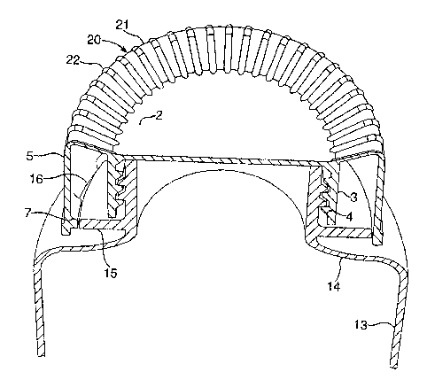
The interaction of the closure cap 1 and the
container 10 is shown more clearly in Fig.3. When the
5 closure cap 1 is fully screwed on to the container 10 the
lugs 7, 8 are engaged in the slots 16, 17 which prevents
the cap 1 from being unscrewed.
The annular bridge portion 20 is shown to comprise a
base 21 formed from material which is relatively thin
compared to the inner 3 and outer 5 skirts and a
plurality of radially extending mutually spaced ribs 22
which extend from the panel 2 to the outer skirt 5. The
localised thinning increases the relative elasticity of
the bridge portion 20 and reduces stress during use. The
bridge portion 20 acts as a spring to provide a sprung
outer skirt 5 as described below.
Whilst the knurling provided by the ribs 22 is
undesirable from the point of the yield of the outer
skirt spring, it provides gripping friction to allow
opening of the closure using the palm of the hand, with
no squeeze force required.
The operation of the closure cap 1 and container 10
will now be more particularly described with reference to
Figs. 4A to 4D. In Fig. 4A the closure cap is shown
fully screwed on to the container as illustrated in
Fig.3. The bridge portion 20 is shown to be upwardly
inclined and the lugs 7, 8 are shown to be engaged in
their respective slots 16, 17. In this position the
closure cap 1 cannot be rotated with respect to the
CA 02455263 2003-12-16
WO 03/006334 PCT/EP02/07463
6
container because of the engagement of the lugs 7, 8 in
the slots 16, 17.
Referring now to Fig.4B, the outer skirt 5 has been
moved to a second position in which the lugs 7, 8 have
been disengaged from their slots 16, 17 and are now below
the level of the locking ring 15. In this position it
will be seen that the bridge portion 20 has moved and is
now in a stressed condition.
With the lugs 7, 8 disengaged from the slots 16, 17
the closure cap 1 can now be partially unscrewed, as the
lugs 7, 8 can pass under the locking ring 15. The bridge
portion is resiliently biassed to the first position but
is unable to urge the outer skirt upwardly due to the
engagement of the lugs 7, 8 under the locking ring 15.
As the closure cap 1 is unscrewed the inner skirt 3
begins to move axially as a result of the screw thread
arrangement. The position of the outer skirt 5 is
unchanged (because of the engagement of the lugs under
the locking ring) but the bridge portion 20 becomes
further stressed as shown in Fig.4C.
The partial unscrewing of the closure cap 1
continues until the lugs 7, 8 are rotated approximately
180-° and they begin to align with the opposite slot 17,
16. When the lugs 7, 8 are fully aligned with the slots
17, 16 the resilience of the bridge portion 20 urges the
outer skirt 5 back to the first position and the lugs 7,
8 pass through the slots 17, 16 due to the axial movement
of the inner skirt during the partial unscrewing. Once
the lugs 7, 8 have passed through the locking ring 15 the
CA 02455263 2003-12-16
WO 03/006334 PCT/EP02/07463
7
closure cap 1 can be fully unscrewed from the container
10.
It will be appreciated that if the slots 16, 17 were
substantially the same size as the lugs the unscrewing
action could not be continuous. Because the slots 16, 17
are considerably longer (in this embodiment approximately
twice as long) than the lugs 7, 8 the unscrewing action
can be continuous; the additional length of the slots
allows the closure cap to be rotated as the lugs 7, 8
move axially through the slots 16, 17. If the slots are
the same size as the lugs the unscrewing action would
have to be in several stages; the user would have to
gently unscrew the closure to the point at which the lugs
flicked fully through the slots, during which time no
rotation would be possible.
When the cap is screwed back onto the closure the
lugs snap back into the slots; the slots prevent over
tightening and serve as an end stop for capping machines.
In other embodiments (not shown) the locking ring is
located on the closure cap and the lugs are located on
the container. The principle behind the operation of
such a closure is exactly the same as previously
described.
In this embodiment the closure cap is injection
moulded in a single piece.
The container may be made by extrusion blowing using
materials such as HDPE or by injection stretch blowing
using materials such as PET. The closure cap may be made
from HPPE, polypropylene or other elastomeric material.
CA 02455263 2003-12-16
WO 03/006334 PCT/EP02/07463
8
Referring now to Fig.5 there is shown a container
110 according to an alternative embodiment. The basic
design and function of the container 110 is the same as
the container 10 of Figs. 1 to 4. In this embodiment the
locking ring 115 is slightly upwardly inclined between
the slots 116, 117. The inclination makes it easier to
unscrew a closure cap (not shown) during the time its
lugs pass under the locking ring 115. Without
inclination, turning of the cap becomes more difficult as
the inner and outer skirts move relative to each other
against the resilience of the bridge portion. The
inclination of the ring 115 reduces the relative movement
of the skirts.
In addition, the locking ring 115 has a stop 118
adjacent each of the Slots 116, 117. The stops 118 have
a ramped surface 119 inclined away from the direction of
unscrewing, and a sheer face 125 which defines the start
of the slot.
The function of the stops 118 is twofold. First,
the face 125 increases the local width of the locking
ring 115 which makes it more difficult for the closure
cap to be forced open, bypassing the push-and-turn
mechanism. Secondly, the ramped surface 119 causes a
change in the force required to screw the closure back
onto the container just before the lugs engage the slots;
the lugs will also pass into the slots with a more
definite clicking noise. This informs the user that the
container is fully closed.