Note: Descriptions are shown in the official language in which they were submitted.
CA 02455480 2004-O1-27
WO 03/016893 PCT/US02/24557
1
TITLE
ELECTROCHEMICAL SENSOR
Cross-Reference to Related Application
This application claims benefit of U.S. Provisional Patent Application
60/311,309 filed August 13, 2001, the contents of which is incorporated herein
by reference.
Background of the Invention
The present invention relates to an electrochemical sensor, and particularly,
to
an electrochemical sensor having improved response time.
In a typical electrochemical gas sensor, the gas to be measured typically
passes from the atmosphere into the sensor housing through a gas porous or gas
permeable
membrane to a working electrode (sometimes called a sensing electrode) where a
chemical
reaction occurs. A complementary chemical reaction occurs at a second
electrode known as a
counter electrode (or an auxiliary electrode). The electrochemical sensor
produces an
analytical signal via the generation of a current arising directly from the
oxidation or
reduction of the analyte gas (that is, the gas to be detected) at the working
and counter
electrodes. A comprehensive discussion of electrochemical gas sensors is also
provided in
Cao, Z. and Stetter, J.R., "The Properties and Applications of Amperometric
Gas Sensors,"
Electroanalysis, 4(3), 253 (1992), the disclosure of which is incorporated
herein by reference.
To be useful as an electrochemical sensor, a working and counter electrode
combination must be capable of producing an electrical signal that is (1)
related to the
concentration of the analyte and (2) su~ciently strong to provide a signal-to-
noise ratio
suitable to distinguish between concentration levels of the analyte over the
entire range of
interest. In other words, the current flow between the working electrode and
the ' counter
electrode must be measurably proportional to the concentration of the analyte
gas over the
concentration range of interest.
CA 02455480 2004-O1-27
WO 03/016893 PCT/US02/24557
2
In addition to a working electrode and a counter electrode, an electrochemical
sensor can include a third electrode, commonly referred to as a reference
electrode. A
reference electrode is used to maintain the working electrode at a known
voltage or potential.
The reference electrode should be physically and chemically stable in the
electrolyte and
carry the lowest possible current to maintain a constant potential.
Electrical connection between the working electrode and the counter electrode
is maintained through an electrolyte. The primary functions of the electrolyte
are: (1) to
efficiently carry the ionic current; (2) to solubilize the analyte gas; (3) to
support both the
counter and the working electrode reactions; and (4) to form a stable
reference potential with
the reference electrode. The primary criteria for an electrolyte include the
following:
(1) electrochemical inertness; (2) ionic conductivity; (3) chemical inertness;
(4) temperature
stability; (5) low cost; (6) low toxicity; (7) low flammability; and (8)
appropriate viscosity.
In general, the electrodes of an electrochemical cell provide a surface at
which
an oxidation or a reduction reaction occurs to provide a pathway whereby the
ionic
conduction of the electrolyte is coupled with the electron conduction of the
electrode to
provide a complete circuit for a current.
The measurable current arising from the cell reactions of the electrochemical
cell is directly proportional to the rate of reaction. Preferably, therefore,
a high reaction rate
is maintained in the electrochemical cell. For this reason, the counter
electrode and/or the
working electrode of the electrochemical cell generally comprise an
appropriate
electrocatalyst on the surface thereof to enhance the reaction rate. If the
reaction rate of
either half cell reaction is impeded, resulting in a low exchange current
density, the
equilibrium current of the electrochemical cell may be changed or perturbed
during
measurement. Such change can result in undesirable side reactions and/or
nonlinear behavior
over the range of analyte concentrations desired to be detected.
CA 02455480 2004-O1-27
WO 03/016893 PCT/US02/24557
3
The type, rate, and efficiency of the chemical reactions within an
electrochemical gas sensor are controlled, in significant part, by the
materials) used to make
the working electrode and counter electrode. Indeed, extensive research
efforts are expended
to develop improved working electrodes, counter electrodes and electrochemical
systems
generally. See Cao, supra.
As illustrated in Figure l, electrodes 110 in electrochemical gas sensors 100
typically include a hydrophobic catalyst layer 120 adhered to a micro-porous,
hydrophobic
membrane 130 such as a Gore-tex~ membrane. Membrane 130 is porous to gases
from the
exterior of sensor 100 but is not porous to the electrolyte 140 contained
within the interior of
sensor 100. Catalyst layer 120 is three-dimensional and hydrophobic. Catalyst
layer 120
thus resists ingress of electrolyte 140 into its internal structure,
especially if a quasi-solid
state electrolyte is used. However, to be detected, the analyte gas
(represented by arrows in
Figure 1) must reach a point where catalyst 120 and electrolyte 140 are in
very close
proximity with one another. The gas must first diffuse through membrane 130,
then into
catalyst layer 120 and then through catalyst layer 120 until it reaches a
catalyst/electrolyte
interface 150. At interface 150, the gas'is oxidized or reduced as described
above. The time
required for the gas to diffuse from the outside environment to such an
interface 150 has a
substantial effect upon the sensor response time.
It is desirable, therefore, to develop new electrochemical sensors and
electrodes for
use in such electrochemical sensors for the detection of analyte gases
exhibiting improved°
response time.
CA 02455480 2004-O1-27
WO 03/016893 PCT/US02/24557
4
Summary of the Invention
In one aspect, the present invention provides an electrode for use in an
electrochemical sensor including a catalyst dispersed within an electrolyte.
Preferably, the
catalyst is immobilized within a matrix of the electrolyte.
In current electrochemical sensors in which a liquid electrolyte is used, the
liquid
electrolyte can penetrate a solid catalyst layer formed on an electrode of the
sensor to provide
conductive contact. In a number of electrochemical sensors (for example,
electrochemical
sensors with metallic housings) it is desirable, however, to immobilize the
electrolyte. In
current sensors with immobilized electrolytes, there is generally no
penetration of a catalyst
layer of an electrode thereof by the immobilized electrolyte. Interfacial
contact between the
electrolyte and the catalyst can thus be diminished as compared to sensors in
which a liquid
electrolyte is used. The present inventors have discovered that good contact
between a
catalyst and an immobilized electrolyte can be achieved, while maintaining
catalyst activity,
by dispersing/immobilizing the catalyst within the electrolyte.
In one embodiment, the electrode of the present invention includes at least
one
catalyst/electrolyte layer having a mixture of a powdered catalyst, a
powdered, quasi-solid
electrolyte and a binder material compressed together. The quasi-solid
electrolyte can
include a liquid electrolyte immobilized by a high-surface-area, high-pore-
volume solid. The
solid can, for example, be Si02. The liquid electrolyte can, for example, be
HZS04. An
example of a suitable binder material is polytetrafluoroethylene.
The electrode can further include at least one electrolyte layer adjacent to
the
catalyst/electrolyte layer. The electrolyte layer can include a mixture of a
powdered, quasi-
solid electrolyte and a binder material compressed together. The electrolyte
layer can be
bound to the catalyst/electrolyte layer. As described above, the quasi-solid
electrolyte of the
CA 02455480 2004-O1-27
WO 03/016893 PCT/US02/24557
electrolyte layer can include a liquid electrolyte immobilized by a high-
surface area, high-
pore volume solid.
In another aspect, the present invention provides an electrochemical sensor
for the
detection of an analyte gas including a housing with at least one working
electrode and at
least one counter electrode disposed therein. The working electrode includes a
catalyst
dispersed within an electrolyte as described above. The catalyst is preferably
immobilized
within a matrix of the electrolyte.
In one embodiment, the working electrode includes at least one
catalyst/electrolyte
layer having a mixture of powdered catalyst, powdered, quasi-solid electrolyte
and binder
material compressed together as described above. The working electrode can
further include
at least one electrolyte layer adjacent to the catalyst/electrolyte layer. The
electrolyte layer
preferably includes a mixture of a powdered, quasi-solid electrolyte and a
binder material
compressed together.
The counter electrode can also include at least one catalyst/electrolyte layer
having a
mixture of powdered catalyst, powdered, quasi-solid electrolyte and binder
material
compressed together. The catalysts of the working electrode and/or the counter
electrode
can, for example, independently be iridium, platinum, carbon, silver or gold.
In one
embodiment, the catalyst of the working electrode is iridium and the catalyst
of the counter
electrode is iridium. Such a sensor is, for example, operable to sense
hydrogen sulfide.
The sensor can further include a reference electrode having at least one
catalyst/electrolyte layer including a mixture of a powdered catalyst, a
powdered, quasi-solid
electrolyte and a binder material compressed together.
In still another aspect, the present invention provides a method of
fabricating an
electrode for use in an electrochemical sensor comprising the step of
dispersing a catalyst
CA 02455480 2004-O1-27
WO 03/016893 PCT/US02/24557
6
within an electrolyte. The catalyst is preferably . immobilized within a
matrix of the
electrolyte.
The step of dispersing a catalyst within an electrolyte can include the step
of forming
a catalyst/electrolyte layer by mixing a powdered catalyst, a powdered, quasi-
solid electrolyte
and a binder material and compressing the mixture. The method can further
include the steps
of: forming an electrolyte layer by mixing a powdered, quasi-solid electrolyte
and a binder
material; and compressing the mixture together. The step of compressing the
mixture of a
powdered, quasi-solid electrolyte and a binder material of the electrolyte
layer can, for
example, be done over the compressed mixture of powdered catalyst, powdered,
quasi-solid
electrolyte and binder material of the catalyst/electrolyte layer to form an
electrolyte layer
bound to the catalyst/electrolyte layer.
The electrodes, sensors and methods of the present invention improve catalyst
electrolyte contact and improve sensor response time as compared to sensors
incorporating
electrodes in which a hydrophobic catalyst layer is deposited upon a porous
membrane.
Moreover, the electrodes of the present invention are relatively easy and
inexpensive to
manufacture in various sizes and, particularly, in reduced size as compared to
currently
available electrodes. The reduced size of the electrodes of the present
invention facilitate the
manufacture of compact sensors. Additionally, the electrodes of the present
invention are
easily formed as, for example, stacks of multiple electrodes or multiple-layer
electrodes for
manufacture of compact sensors suitable for detection of multiple analytes.
The electrodes of
the present invention are also suitable for use with generally any
electrolyte, including
aqueous, inorganic andlor organic electrolytes. The electrolytes used with the
electrodes of
the present invention can also be acidic, basic or neutral. Still further, the
electrodes of the
present invention have been found to provide improved response signals,
particularly with
catalyst materials of intrinsically low surface area (for example, gold).
CA 02455480 2004-O1-27
WO 03/016893 PCT/US02/24557
7
Brief Description of the Drawings
Figure 1 illustrates a side cross-sectional view of a portion of a sensor
incorporating an electrode in which a catalyst is deposited upon a porous
membrane.
Figure 2A illustrates a side cross-sectional view of a sensor incorporating a
bi-
layer, composite electrode of the present invention.
Figure 2B illustrates a top plan view of the electrode of Figure 2A.
Figure 3A illustrates a disassembled or exploded view of a two-electrode
sensor including two bi-layer electrodes of the present invention.
Figure 3B illustrates a side view of the sensor of Figure 3A in an assembled
state.
Figure 4A illustrates a side, cross sectional view of a portion of a sensor
including a plurality of bi-layer electrodes of the present invention.
Figure 4B illustrates a top perspective view of the sensor portion of
Figure 4A.
Figure 4C illustrates a top perspective view of another sensor including a
plurality of bi-layer electrodes of the present invention.
Figure 5 illustrates an embodiment of a tri-layer composite electrode of the
present invention.
Figure 6 illustrates a graph of the output of several two-electrode HZS
sensors
of the present invention.
CA 02455480 2004-O1-27
WO 03/016893 PCT/US02/24557
8
Figure 7 illustrates a graph of the output of several two-electrode CO sensors
of the present invention.
Figure 8 illustrates a graph of the output of several two-electrode NOZ
sensors
of the present invention. .
Figure 9 illustrates a graph of the output of several two-electrode SOZ
sensors
of the present invention.
Figure 10 illustrates a graph of the output of several two-electrode NO
sensors
of the present invention.
Figure 11 illustrates a graph of a comparison of the output of a two-electrode
NO sensor of the present invention and two three-electrode NO sensors of the
present
invention.
Detailed Description of the Invention
It is believed that the electrodes of the present invention improve response
time of sensors incorporating the electrodes by making regions where catalyst
and electrolyte
form an interface favorable to reaction more available to the analyte gas. The
electrodes of
the present invention can be formed as mufti-layer pellets. The pellet has at
least one layer
including a mixture of catalyst powder and a powdered'quasi-solid state
electrolyte. Mixing
the catalyst and the electrolyte together results in intimate contact between
the catalyst and
the electrolyte. The relatively thick, hydrophobic catalyst layer
characteristic of currently
available electrodes is eliminated. The analyte gas has direct access to
catalyst/electrolyte
interfaces immediately, for example, after passing through a membrane,
resulting in faster
response times.
CA 02455480 2004-O1-27
WO 03/016893 PCT/US02/24557
9
Figures 2A and 2B illustrate a bi-layer pellet electrode 210 of the present
invention. As illustrated in Figure 2B, bi-layer pellet electrode 210 is of
generally circular
shape. Bi-layer pellet electrode 210 includes an electrolyte layer 220 and a
catalystlelectrolyte layer 230. Electrolyte layer 220 is made from a composite
powder
containing a mixture an electrolyte material, a powder having a relatively
high surface area
and a relatively high pore volume and a binder material. In general, the
powder is a porous
powder such as a porous ceramic or a porous polymer.
Binder materials used in the present invention can be polymeric materials that
are suitable to form a three-dimensional matrix around and thus bind together
the electrolyte
material. The binder material is preferably generally inert to the electrolyte
material, to the
catalyst and to substances to which the sensor will be exposed during use. An
example of a
suitable binder material is a polymer such as TEFLON (polyfluorotetraethylene
or PTFE) and
like materials that are generally inert and have glass transitions temperature
above which the
polymer softens and can flow (for example, during pressing) to form a three-
dimensional
matrix or support, binding the electrolyte material together. A binder
material for use in the
present invention can also be a powder having a particle size different from
the particle size
of the electrolyte material that is suitable to form an interlocking matrix
with the electrolyte
material.
In several electrodes studied in the present invention, the electrolyte was
HZSOd, the high-surface-area, high-pore-volume powder was Si02 and the binder
was PTFE
(TEFLON). An example of a suitable Si02 powder is SIPERNAT~ 22 (a synthetic
amorphous precipitated silica powder) available from Degussa AG of Frankfurt,
Germany.
That silica powder was indicated by the manufacturer to have a BET surface
area of
approximately 190 m2/g. Catalyst/electrolyte layer 230 was made from the same
mixture of
materials used in the electrolyte layer 220 with the addition of an
appropriate catalyst
powder.
CA 02455480 2004-O1-27
WO 03/016893 PCT/US02/24557
In several studies of the present invention, electrolyte layer 220 was first
made
by compressing a volumetrically measured sample of the above-described mixture
in a die
cavity. A second volumetrically measured sample of catalyst/electrolyte layer
mixture is
then pressed on top of electrolyte layer 220 to produce one, bi-layer pellet
electrode 210. Of
course, the order of formation of the layers can be reversed.
To produce a two-electrode sensor, two bi-layer pellets 210 can, for example,
be placed back to back in the sensor assembly with their electrolyte layers
220 touching.
This assembly provides ionic contact for sensor operation. The bi-layer pellet
that is placed
closest to the inlet hole in the sensor can function as the sensing (working)
electrode. The bi-
layer pellet that is placed farthest away from the inlet hole can function as
the
counter/reference electrode. Selectivity for a specific target gas is obtained
by choosing the
appropriate catalyst combination for the sensing pellet electrode and the
counter/reference
pellet electrode. Three-electrode sensors can be made by adding an additional
bi-layer pellet
electrode to serve exclusively as a reference electrode, as opposed to a
counter/reference
electrode. The reference pellet electrode can, for example, be placed between
the sensing and
counter pellet electrodes.
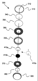
Figures 3A and 3B illustrate an assembly of one embodiment of a two-
electrode sensor 300 of the present invention. Sensor 300 is housed within a
metallic cell or
case as described, for example, in U.S. Patent No. 5,906,726 and U.S. Patent
No. 5,667,653,
the contents of which are incorporated herein by reference. In that regard,
sensor 300
includes a first case member 310 in which an inlet 312 is formed to allow
analyte gas to enter
sensor 300 from the surrounding environment. Sensor 300 also includes a second
case
member 320 which can be crimped under first case member 310 to form the outer
housing of
sensor 300 as illustrated in Figure 3B.
A gasket 330 can be placed within sensor 300 to assist in forming an adequate
connection/seal between case members 310 and 320, to provide electrical
insulation between
CA 02455480 2004-O1-27
WO 03/016893 PCT/US02/24557
11
case members 310 and 320, and to assist in positioning the other components of
sensor 300
within the sensor housing. One or more filters 340 and 350 can be placed
adjacent first case
member 310 within sensor 300. Filter 340 can, for example be a spun mat glass
filter
suitable, for example, to diffuse gas entering sensor 300 and/or to remove
interferants.
Filter 350 can, for example, be a porous GORE-TEX~ membrane available from
W.L. Gore
& Associates and suitable to filter solids and liquids, but porous to gases.
In the embodiment
of Figures 3A and 3B, a screen contact member 360 is placed in electrical
contact with the
electrolyte/catalyst layer of bi-layer pellet working electrode 410a and with
first case
member 310. A second screen contact member 370 is placed in electrical contact
with the
electrolyte/catalyst layer of bi-layer pellet counter electrode 410b and with
second case
member 320. A buffer or spacer 380 is placed between pellet counter electrode
410b and
second case member 320.
As illustrated in Figures 4A and 4B, several pellet electrodes S 10a, S l Ob,
S l Oc
~~~ can be incorporated into a sensor 500 for the detection of multiple
analyte gases. Each of
bi-layer pellet electrodes S 10a, S l Ob, S l Oc ~~~ can, for example, be
fabricated as described
above. However, each of electrolytelcatalyst layers 520a, 520b, 520c ~~~ can
include a
different catalyst (for example, platinum (Pt), iridium (Ir), gold (Au) etc.)
as desired to
catalyze a reaction of and thereby sense the presence of different analyte
gases. Electrical
contact members 540a, 540b, 540c ~~~ are placed in contact with
electrolyte/catalyst layers
520a, 520b, 520c ~~~ to carry a signal to, for example, a measurement circuit
as known in the
art. In the embodiment of Figures 4A and 4B, electrodes S 10a, S l Ob, S l Oc
~~~ are, for
example, formed in, the shape of a cylindrical rings with passages SSOa, SSOb,
SSOc ~~~
formed generally centrally therein. Passages SSOa, SSOb, SSOc ~~~ form a
composite passage
generally through the center of sensor 500 when electrodes S 10a, S l Ob, S l
Oc ~~~ are stacked
in general alignment through which analyte gasses can pass to contact
catalyst/electrolyte
layers 520a, 520b, 520c ~~~.
CA 02455480 2004-O1-27
WO 03/016893 PCT/US02/24557
12
Figure 4C .illustrates another embodiment of a sensor 600 in which several
pellet electrodes 610a, 610b, 610c ~~~ can be incorporated into a sensor 600
for the detection
of multiple analyte gases. Each of bi-layer pellet electrodes 610a, 610b, 610c
~~~ can, for
example, be fabricated as described above. Each of electrolyte/catalyst layers
620a, 620b,
620c ~~~ can include a different catalyst as described above. In the
embodiment of
Figure 4C, sensor 600 can be formed by first forming a generally circular or
generally oval
composite sensor, which is subsequently sliced/bisected to form two generally
semicircular
sensors 600 in which electrodes 610a, 610b, 610c ~~~ are stacked in general
alignment and
wherein analyte gasses can contact catalyst/electrolyte layers 620a, 620b,
620c ~~~ at the
open face of electrode 600 created during bisection.
Moreover, the electrodes of the present invention can also be formed as multi-
layer pellets other than bi-layer electrode. For example, Figure 5 illustrates
a tri-layer pellet
electrode 710 including a first electrolyte/catalyst layer 720a, an
intermediate electrolyte
layer 730 and a second electrolyte/catalyst layer 720b. The catalysts of first
electrolyte/catalyst layer 720a and second electrolyte/catalyst layer 720b can
be different.
Electrolyte/catalyst layers 720a and 720b, electrolyte layer 730 and any other
electrolyte or
electrolyte/catalyst layers can be formed generally as described above. -
EXPERIMENTAL EXAMPLES
A number of electrodes as illustrated in Figures 3A and 3B were tested for
various analyte gases using various electrode catalysts in a two-electrode
sensor
configuration as summarized in Table 1. The catalysts used in the studies of
the present
invention are fiu~ther characterized in Table 2.
CA 02455480 2004-O1-27
WO 03/016893 PCT/US02/24557
13
Table 1
AnalyteActive Catalyst Active Catalyst Bias
Gas Working ElectrodeCounter ElectrodePotential
HZS Iridium Iridium 0 mV
CO Platinum Platinum 0 mV
NOZ Activated Carbon Activated Carbon0 mV
S02 Gold Platinum 0 mV
NO Carbon Platinum +300 mV
NH3 Iridium Iridium +235 mV
Table 2
Catalyst Manufacturer Surface Area, Sensor
m2lg
Iridium Englehard 15.5-21.5 HZS
Platinum Englehard >25 CO, SOz, NO
Activated CarbonJohnson MattheyNot Available NOZ (75%)
Carbon Black Cabot 94 NOZ (25%)
(Regal 330R)
Gold Technic Inc. 0.4-1.0 SOZ
Graphite Sigri Great Not Available NO
(EG-31) Lakes
Carbon Co.
Each of the sensors studied included a working and counter electrode as
described above. In
forming the bi-layer electrodes, the electrolyte was HzSO4, the high-surface-
area, high-pore-
volume powder was SiO2 and the binder was PTFE (TEFLON). As set forth in Table
1, in
the case of HZS (hydrogen sulfide), CO (carbon monoxide) and NOZ (nitrogen
dioxide)
analyte gases, the catalyst on the working and counter electrodes was the
same. In the case of
SO2 (sulfur dioxide) and NO (nitric oxide) analyte gases , the catalyst on the
working and
counter electrodes was different. The NO sensor was operated at a positive
bias potential
(approximately +300mV), whereas the other sensors were operated at a zero bias
potential.
CA 02455480 2004-O1-27
WO 03/016893 PCT/US02/24557
14
Studies were also performed upon NO sensors having a three-electrode
configuration (working electrode, counter electrode and reference electrode).
As with the
two-electrode NO sensors, the three-electrode NO sensors were operated at a
positive bias
potential of approximately +300mV.
In general, the present studies were performed under computer control in
which twenty (20) sensors could be tested simultaneously. A baseline current
reading for
each sensor was established as the sensor output after an exposure to air (0
ppm analyte gas).
In testing for analyte gas concentration, air was first applied to the sensors
for a period of
time followed by application of air having a known concentration of analyte
gas for a period
of time. A purge with air followed exposure to analyte gas in some
experiments.
In general, the response time of the sensors of the present invention are
substantially improved as compared to sensors in which currently available
electrodes are
used. Response time is a measure of the speed of response of a sensor and can
be dependent
on the manner in which the test is performed (for example, the length of time
the experiment
lasts and/or the time at which the sensor reaches 100% of its final output).
In the present
studies, response times were based on exposure to test gas for a known amount
of time.
Response time was generally tabulated as the 90% response time (t9°)
unless otherwise
indicated. The t9° response time is the time, in seconds, required for
the sensor to reach 90%
of a generally stable response or output. The sensitivity (in units of wAlppm
analyte) was
established as the sensor output after exposure to analyte gas for a
sufficient period of time to
reach a stable output.
Hydrogen Sulfide~Sensors
As described in Table 1, HZS sensors of the present invention included a bi-
layer working electrode having an iridium catalyst and a bi-layer counter
electrode having an
iridium catalyst. The electrodes and the sensors were formed generally as
described above in
CA 02455480 2004-O1-27
WO 03/016893 PCT/US02/24557
connection with Figures 2A through 3B and as further described below. Figure 6
illustrates
the measured output for several such sensors over time during operation with a
potentiostat at
0 mV bias potential. The experiments of Figure 6 included 2 minutes of
baseline in which
the sensor was exposed to air without analyte gas, followed by 5 minutes of
analyte gas
exposure (50 ppm HzS), followed by 2 minutes of air purge.
Table 2 summarizes results for 200 sensors using bi-layer electrodes of the
present invention and 200 sensors using currently available electrodes in
which catalyst is
deposited upon a porous membrane. Errors reported in Table 3 represent one
standard
deviation.
Table 3.
Electrode Type Sensitivity . Response Time, T9o
(Microamps/ppm) (Seconds)
Catalyst deposited on 0.194 ~ 0.023 149 ~ 36
membrane
Bi-layer composite electrode0.189 ~ 0.034 15 ~ 4
Carbon Monoxide Sensors
As described in Table 1, CO sensors of the present invention included a bi-
layer working electrode having an platinum catalyst and a bi-layer counter
electrode having
an platinum catalyst. The electrodes and the sensors were formed generally as
described
above in connection with Figures 2A through 3B. Figure 7 illustrates the
measured output ,
for several such sensors over time during galvanic operation using a 500 ohm
resistor. The
experiments of Figure 7 included 1 minute of baseline in which the sensor was
exposed to air
without analyte gas (100 ppm CO), followed by 15 minutes of analyte gas
exposure.
CA 02455480 2004-O1-27
WO 03/016893 PCT/US02/24557
16
Nitrogen Dioxide Sensors
As described in Table l, NOZ sensors of the present invention included a bi-
layer working electrode having an activated carbon catalyst and a bi-layer
counter electrode
having an activated carbon catalyst. The activated carbon in each electrode
was 75%
activated carbon and 25% carbon black. The electrodes and the sensors were
formed
generally as described above in connection with Figures 2A through 3B. Figure
8 illustrates
the measured output for several such sensors over time during operation with a
potentiostat at
0 mV bias potential. The experiments of Figure 8 included 2 minutes of
baseline in which
the sensor was exposed to air without analyte gas, followed by 10 minutes of
analyte gas
exposure (44 ppm NOZ), followed by 2, minutes of air purge.
Sulfur Dioxide Sensors
As described in Table l, SOZ sensors of the present invention included a bi-
layer working electrode having a gold catalyst and a bi-layer counter
electrode having a
platinum catalyst. The electrodes and the sensors were formed generally as
described above
in connection with Figures 2A through 3B. Figure 9 illustrates the measured
output for
several such sensors over time during operation with a potentiostat at 0 mV
bias potential.
The experiments of Figure 9 included 2 minutes of baseline in which the sensor
was exposed
to air without analyte gas, followed by 10 minutes of analyte gas exposure (12
ppm SOa),
followed by 2 minutes of air purge.
Nitric Oxide Sensors (two electrode configuration)
As described in Table l, NO sensors of the present invention included bi-layer
working electrode having a carbon catalyst and a bi-layer counter electrode
having a platinum
catalyst. The electrodes and the sensors were formed generally as described
above in
connection with Figures ZA through 3B. Figure 10 illustrates the measured
output for several
CA 02455480 2004-O1-27
WO 03/016893 PCT/US02/24557
17
such sensors over time during operation with a potentiostat at +300 mV bias
potential. The
experiments of Figure 9 included 2 minutes of baseline in which the sensor was
exposed to
air without analyte gas, followed by 5 minutes of analyte gas exposure (49 ppm
NO),
followed by 2 minutes of air purge. Data including response times for several
NO sensors
are also set forth in Table 4.
Table 4.
Base Current Output Response Response Time
Sensor (uAmps) (uA/PPlVn (Secs)
1 3.326 0.870 45
2 2.338 0.763 14
3 3.920 0.836 45
4 2.360 0.781 17
Often, electrochemical sensors are subjected to a "cook-down" or
"equilibration" period before use thereof to provide an adequately stable and
low baseline
current. During the cook-down or equilibration period, the electrochemical
sensor is stored
at ambient conditions and maintained at operating potential for a defined
period of time. A
cook-down period of approximately 4 hours was used in the studies of Figure 9
and Table 4.
Nitric Oxide Sensors (three electrode configuration)
Three-electrode NO, sensors of the present invention included a bi-layer
working electrode having a carbon catalyst, a bi-layer counter electrode
having a platinum
catalyst and a bi-layer reference electrode having a platinum catalyst. The
electrodes and the
sensors were formed generally as described above in connection with Figures 2A
through 3B.
However, a reference electrode was included in sensor 2 and 3 of Figure 1 l
and Table 5. The
three-electrode sensor was prepared generally in the manner described in U.S.
Patent
No. 5,906,726 and U.S. Patent No. 5,667,653. Sensor 1 included only a working
electrode
and a counter electrode as described above. Figure 11 illustrates the measured
output for
CA 02455480 2004-O1-27
WO 03/016893 PCT/US02/24557
18
several such sensors over time during operation with a potentiostat at +300 mV
bias
potential. The experiments of Figure 11 included 2 minutes of baseline in
which the sensor
was exposed to air without analyte gas, followed by 5 minutes of analyte gas
exposure
(49 ppm NO), followed by 2 minutes of air purge. An overnight cook-down period
was use
in the studies. Data including response times for the two-electrode NO sensor
and the two
three-electrode NO sensors are set forth in Table S.
Table 5.
Base Current Output Response Response Time
Sensor (uAmps) (uAIPPM) (Sees)
1 1.528 0.709 113
2 3.013 0.754 172
3 1.450 0.918 45
Ammonia Sensors (neutral or basic electrolyte)
Ammonia sensors were fabricated similarly to other bi-layer sensors described
above. The electrolyte used was 5 M LiCI solution, absorbed onto an SiOz
support in a
0.75:1 weight ratio (I,iCl:Si02). The catalyst was Ir powder. The electrodes
and the sensors
were formed generally as described above in connection with Figures 2A through
3B. The
ammonia sensors were operated in the electrolytic mode at approximately +235
mV in
sensing ammonia gas.
Preparation of Electrolyte Powder
In preparation of typical preparation, approximately 190 grams of precipitated
silica (DeGussa SIPERNAT 22) was placed into a round, 1/2 gal. Nalgene mixing
container
under a ventilated hood. Approximately 165 grams of PTFE powder (Dupont Teflon
850A)
was then added to the mixing container. The mixing container was then closed
and lightly
shaken to pre-mix the components.
CA 02455480 2004-O1-27
WO 03/016893 PCT/US02/24557
19
Approximately 145 grams of 6.7N sulfuric acid was then poured into the pre-
mixed
powder. The cap was then closed and the container gently shaken for a few
seconds to
disperse the liquid. The mixing container was then tumbled for 15-20 minutes
at
approximately 40 rpm using a LorTone rock tumbler.
Preparation of Electrolyte/Catalyst Powder
In a typical ease of an iridium catalyst as described above, each pellet of a
sensor included approximately 0.06 grams of electrolyte/catalyst powder per
pellet. The
electrolyte/catalyst powder was approximately 50 % electrolyte powder as
described above
and approximately 50 % catalyst blend powder as described below.
In one example, 2.4 grams PTFE (DuPont Teflon 850A), 0.8 grams graphite,
0.8 grams precipitated silica (DeGussa SIPERNAT were added to a mixing
container. After
addition of these components, the container was lightly shaken for about 5
minutes. Then the
electrolyte powder was added. Approximately, 8 grams of Iridium powder were
added to the
mixing container. The mixing container was then place in a rubber sleeve and
tumbled using
a LorTone rock tumbler for about 15 minutes at approximately 40 rpm.
Preparation of Pellets
In forming a bilayer pellet, the cavity of a die having a fill depth of
approximately 0.117 inches and a diameter of approximately 0.5 in. was first
filled with
electrolyte powder as descried above flush with the top of the die. A metal
rod was used to
gently tamp the powder down. A first stop was then slid over the die; causing
a small
depression. This depression defined the fill depth for the
electrolyte/catalyst powder as
describe above. The resulting cavity or depression was then filled with a
small amount of
catalystlelectrolyte powder. Excess powder was scraped off so that the powder
was flush
with the top of the die. The top platen was place on the top of the cavity,
and the die was slid
CA 02455480 2004-O1-27
WO 03/016893 PCT/US02/24557
under a ram. The pellet was then pressed with a dwell time at the bottom of
the stroke of
approximately 3-5 seconds. The ram was in operative connection to a 6 inch air
cylinder to
which compressed air was supplied at a pressure of approximately 90 to
approximately 110
psi. After retraction of the die, the pellet was removed. In general, the
bilayer pellet
electrodes used in the studies of the present invention had a thickness in the
range of
approximately .044 to approximately .047 inches. The electrolyte layer of the
bilayer pellet
electrodes was in the range of approximately 0.037 to approximately .040
inches thick.
Although the present invention has been described in detail in connection with
the above examples, it is to be understood that such detail is solely for that
purpose and that
0 variations can be made by those skilled in the art without departing from
the spirit of the
invention except as it may be~limited by the following claims.