Note: Descriptions are shown in the official language in which they were submitted.
CA 02455652 2006-09-07
SHINGLE PANEL
FIELD OF THE INVENTION
This invention relates generally to exterior residential or commercial siding.
BACKGROUND OF THE INVENTION
Traditional residential or commercial siding is made of various materials in a
variety of shapes and is installed in different ways. A classic siding
includes wood-based
shingles affixed independently to the side of a building. To improve
installation
efficiency, multiple shingles can be joined together to form pre-made shingle
panels, for
example 3-course shingle panels. 3-course shingle panels provide three pre-
made rows of
shingle panels, allowing an installer to affix multiple shingles in much less
time.
However, 3-course shingle panels result in significant waste during
installation.
SUMMARY OF THE INVENTION
Illustrative embodiments of the invention include a shingle panel and method
for
making the same. The shingle panel includes at least one shingle having a
first edge, a
second edge, a third edge and a fourth edge, wherein the first edge is
substantially
opposite the second edge and the third edge is substantially opposite the
fourth edge and
at least one backing affixed to the shingle, the backing having a first edge,
a second edge,
a third edge and a fourth edge, wherein the first edge is substantially
opposite the second
edge and the third edge is substantially opposite the fourth edge. The first
edge of the
backing is substantially aligned with the first edge of the shingle, the
second edge of the
backing is offset the second edge of the shingle, the third edge of the
backing is offset the
third edge of the shingle and the fourth edge of the backing is offset the
fourth edge of the
shingle.
In an alternative embodiment, the shingle of the shingle panel has a thickness
and
the thickness is tapered from the second edge to the first edge of the
shingle.
In yet an alternative embodiment, the shingle of the shingle panel has at
least one
groove extending substantially between the first and second edges of the
shingle.
-1-
CA 02455652 2006-09-07
In an alternative embodiment, the backing of the shingle panel includes at
least
one breathing groove substantially parallel with the third and fourth edges of
the backing
and extending from the first edge of the backing.
In accordance with another illustrative embodiment of the present invention,
there
is provided a method for manufacturing a shingle panel. The method includes
affixing a
first backing to a first side of at least one shingle board having first and
second sides,
wherein the first side of the shingle board is substantially opposite the
second side of the
shingle board. A second backing is affixed to the second side of the shingle
board. The
shingle board affixed between the first and second backings is separated to
produce at
least one shingle panel. The resultant shingle panel includes at least one
shingle
associated with the first or second backing, the shingle having a first edge,
a second edge,
a third edge and a fourth edge, wherein the first edge is substantially
opposite the second
edge and the third edge is substantially opposite the fourth edge. The
associated first or
second backing has a first edge, a second edge, a third edge and a fourth
edge, wherein
the first edge is substantially opposite the second edge and the third edge is
substantially
opposite the fourth edge. The first edge of the associated first or second
backing is
substantially aligned with the first edge of the shingle. An offset is
produced in the second
edge of the associated first or second backing relative to the second edge of
the shingle.
Additional offsets are produced in at least one of the third and fourth edges
of the
associated first or second backing.
In an alternative embodiment, the first and second backings are compression
pressed to the shingle and allowed to cure for a predetermined period of time.
In yet an alternative embodiment, the shingle has a thickness and the shingle
board is separated between the affixed first and second backings at an angle
relative to the
first and second backings to produce a taper from the second to the first
edges of the
shingle.
In an alternative embodiment, a breathing groove is produced substantially
parallel with the third and fourth edges of the backing in at least one of the
first and
second backings, and the breathing groove extends from the first edge of the
backing.
-2-
CA 02455652 2006-09-07
An illustrative embodiment of the invention is also directed to a method for
installing a shingle panel system on a building exterior. A first shingle
panel is affixed to
the building exterior. The first shingle panel includes at least one shingle
having a first
edge, a second edge, a third edge and a fourth edge, wherein the first edge is
substantially
opposite the second edge and the third edge is substantially opposite the
fourth edge, a
backing affixed to the shingle, the backing having a first edge, a second
edge, a third edge
and a fourth edge, wherein the first edge is substantially opposite the second
edge and the
third edge is substantially opposite the fourth edge, and wherein the first
edge of the
backing is substantially aligned with the first edge of the shingle, the
second edge of the
backing is offset the second edge of the shingle, the third edge of the
backing is offset the
third edge of the shingle and the fourth edge of the backing is offset the
fourth edge of the
shingle.
A second shingle panel is then affixed to the building exterior, the second
shingle
panel including at least one shingle having a first edge, a second edge, a
third edge and a
fourth edge, wherein the first edge is substantially opposite the second edge
and the third
edge is substantially opposite the fourth edge, a backing affixed to the
shingle, the
backing having a first edge, a second edge, a third edge and a fourth edge,
wherein the
first edge is substantially opposite the second edge and the third edge is
substantially
opposite the fourth edge, and wherein the first edge of the backing is
substantially aligned
with the first edge of the shingle, the second edge of the backing is offset
the second edge
of the shingle, the third edge of the backing is offset the third edge of the
shingle and the
fourth edge of the backing is offset the fourth edge of the shingle.
The first shingle panel is affixed to the building exterior along the first
edge of the
shingle of the first shingle panel. The second shingle panel is affixed to the
building
exterior along the first edge of the shingle of the second shingle panel. The
second shingle
panel is positioned relative the first shingle panel such that the first edge
of the first and
second shingle panels are substantially aligned, the third edge of a second
shingle panel
substantially abuts the fourth edge of the first shingle panel, and the offset
of the third
-3-
CA 02455652 2004-01-22
edge of the second shingle panel interlocks with the offset of the fourth edge
of the first
shingle panel.
In an alternative embodiment, a third shingle panel is affixed to the building
exterior, the third shingle panel including at least one shingle having a
first edge, a second
edge, a third edge and a fourth edge, wherein the first edge is substantially
opposite the
second edge and the third edge is substantially opposite the fourth edge, a
backing affixed
to the shingle, the backing having a first edge, a second edge, a third edge
and a fourth
edge, wherein the first edge is substantially opposite the second edge and the
third edge is
substantially opposite the fourth edge, and wherein the first edge of the
backing is
substantially aligned with the first edge of the shingle, the second edge of
the backing is
offset the second edge of the shingle, the third edge of the backing is offset
the third edge
of the shingle and the fourth edge of the backing is offset the fourth edge of
the shingle.
The third shingle panel is affixed to the building exterior along the first
edge of the
shingle of the third shingle panel. The third shingle panel is positioned
relative the first
and second shingle panels such that the second edge of the third shingle panel
is aligned
with the first edge of the first and second shingle panels such that the
second edge of the
third shingle panel overlaps the first edge of the first and second shingle
panels
substantially to the offset of the backing along the second edge of the third
shingle panel.
As will be readily appreciated from the foregoing summary, the invention
provides a more efficient and cost-effective shingle siding system.
BRIEF DESCRIPTION OF THE DRAWINGS
The preferred and alternative embodiments of the present invention are
described
in detail below with reference to the following drawings.
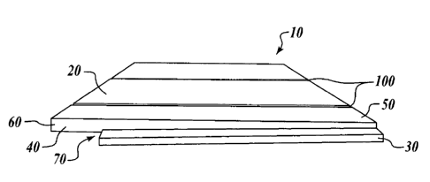
FIGURE 1 is an illustration showing a front view of the preferred embodiment
of
the present invention;
FIGURE 2 is an illustration showing a back view of the preferred embodiment of
the present invention;
-4-
CA 02455652 2004-01-22
FIGURE 3 is an illustration showing a side view of the preferred embodiment of
the present invention;
FIGURE 4 is an illustration showing multiple shingle panels of the present
invention in interlocking fashion;
FIGURE 5 is an illustration showing a front view of the preferred embodiment
of
the present invention including keyway joints;
FIGURE 6 is an illustration showing a back view of the preferred embodiment of
the present invention including keyway joints;
FIGURE 7 is an illustration showing a perspective side view of the preferred
embodiment of the present invention including keyway joints;
FIGURE 8 is an illustration showing a front view of the preferred embodiment
of
the present invention having an even-butt line together with a tight
contemporary joint;
FIGURE 9 is an illustration showing a front view of the preferred embodiment
of
the present invention having a staggered-butt line together with keyway
joints;
FIGURE 10 is an illustration showing a perspective side view of a shingle
board
having a keyway joint notch;
FIGURE 11 is an illustration showing a side view of a shingle panel "sandwich"
made in accordance with a preferred embodiment of the present invention prior
to being
cut into shingle panels; and
FIGURE 12 is a flowchart describing a preferred method of manufacturing a
shingle panel in accordance with the present invention.
DESCRIPTION OF THE PRESENT INVENTION
As shown with reference to the accompanying drawings and photographs, the
present invention is directed to an improved shingle panel and method for
creating the
same that provides superior benefits over traditional shingle panels. As shown
in
FIGURES 1-3, and with further reference to FIGURES 5-7, the preferred
embodiment of
the present shingle panel 10 consists of one or more Western Red cedar
shingles 20 held
together by a 3-layer plywood backing 30 that is glued or otherwise affixed to
each
-5-
CA 02455652 2004-01-22
shingle 20. The backing 30 preferably extends fully from a first edge 50 of
the shingle 20
the majority of the way to a second edge 60 of the shingle, thereby providing
support for
the shingle. The backing 30 preferably terminates short of the second edge 60
of the
shingle to provide an alignment line 70. This alignment line is used during
installation to
vertically align shingle panels. The alignment line also facilitates the
overlap of vertically
adjacent shingle panels, which in turn allows blind/concealed nailing of the
shingle
panels.
In the preferred embodiment, the backing 30 is staggered to provide
overlocking
end joints 80 and corresponding recessed end joints 90. This allowed multiple
horizontally adjacent shingle panels to be seamlessly interconnected to
provide closely
abutting shingles. This also avoids exposed portions of the paper normally
applied behind
the siding.
In the preferred embodiment, each shingle is cut in a tapered fashion (see
FIGURE 3) to provide for a thick butt 40 at the second end 60 of each shingle
20. This
provides an enhanced visual depth to the installed shingle panel, creating an
improved
"shadow-line." Alternatively, each shingle may be cut in a non-tapered fashion
(not
shown). As illustrated with reference to FIGURES 1, 5 and 7, the shingle panel
may be
formed using shingles having keyway joints 100. Keyway joints are grooves cut
along the
surface of the shingle facing away from the house or other exterior to which
the shingle
panel is applied. The keyway joints provide texturing for the shingle to
further enhance
the appearance of the building surface, as well as a way to hide or reduce
visibility of
manufacture seam lines between adjoined shingles. The keyway joints are
preferably cut
along the vertical line of the shingle, The keyway joint may be cut to a
uniform depth
along the shingle. Alternatively, the keyway joint may be cut unevenly so as
to produce a
tapered depth of the joint between edge 50 and edge 60 of the shingle.
In an alternative embodiment, the shingle panel may be formed without a keyway
joint, instead having a tight contemporary joint between shingles (FIGURE 8).
Likewise,
the preferred embodiment is shown using shingles arranged with an even-butt
-6-
CA 02455652 2004-01-22
configuration. Alternatively, the shingle panel may be formed with shingles of
varying
lengths, creating a staggered-butt line configuration (FIGURE 9).
In an alternative embodiment, as shown with reference to FIGURES 2 and 6,
breathing grooves 110 are notched into one or more locations along the backing
30 of the
shingle panel, preferably along first edge 50 of one or more shingles 20. When
the shingle
panels are installed on the exterior of a building, breathing grooves allow
moisture and air
to flow vertically behind the shingle panels down the side of the building.
This facilitates
removing moisture from behind the siding, thereby reducing the possibility of
accelerated
weathering and deterioration of the shingle panels, the siding paper typically
applied
between the shingle panels and the exterior of the building, and the building
surface.
Various material alternatives to cedar for the shingles 20 and plywood for the
backing 30 may be used. Examples of alternative shingle material include
Eastern White
Cedar, Alaskan Yellow Cedar (Cyprus), Southern Yellow Pine, Fir, Spruce, or
any other
wood or other material suitable for exterior siding. The shingles can be
unfinished,
primed or finished. Shingles may be finished using any one of a number of
finishes, for
example, semi-transparent oil stain in colors such as Pasadena Green, Beach
Grey,
Redwood and Natural Beige. The shingles are preferably finished with an
application
useful to reduce or eliminate UV rays. Examples of alternative backing
material include
plywood of different layers, particle board, or any other wood or other
material suitable
for supporting shingles in the context of exterior siding.
As shown with reference to FIGURES 1 and 4, multiple shingle panels 10 are
preferably installed in an interlocking and overlapping fashion. Specifically,
in the
horizontal direction, the recessed end joint 90 of a shingle panel 10
interlocks with the
overlapping end joint 80 of an adjacent shingle panel. In the vertical
direction, shingle
panels are preferably nailed, stapled or otherwise affixed to the building
side by placing
nails (or their equivalent) through the shingle and backing near the first
edge 50 of the
shingles. The alignment line 70 of a subsequently installed vertically
adjacent shingle
panel is positioned to abut the first edge 50 of the previously installed
shingle panel such
-7-
CA 02455652 2004-01-22
that the thick butt 40 at the second end 60 of the shingle overlaps the first
end 50 of the
previously installed shingle, thereby hiding the affixation nail.
The preferred method of manufacturing shingle panels 10 of the present
invention
is described with reference to FIGURES 10 and 11 and the flowchart shown in
FIGURE 12. A shingle panel 10 is preferably manufactured by sandwiching a
finished
shingle board 120 between two plywood backings 140. A shingle board is
finished
through a trimming, sanding and cutting process to produce a shingle board of
the desired
size and shape. If a keyway joint configuration is desired, each shingle board
is notched
along one edge. In this example, the shingle board 120 includes a keyway joint
notch 130
so that the finished shingle panel 10 will include a keyway joint 100.
The preferred method of manufacturing a shingle panel is more fully described
with reference to FIGURE 12, At block 200, a plurality of finished shingle
boards are
placed adjacent to each other. At blocks 202 and 204, glue or other bonding
material,
preferable PVA (poly vinyl acetate), is placed along the side 150 of the two
plywood
backing pieces facing the shingle board 120. A full gluing process is
preferably used
rather than a beading or combination beading and staple process. In the
preferred
embodiment, at blocks 206 and 208, the configuration is compression pressed
together for
twenty minutes and allowed to cure 24 hours at 55 degrees.
After the combination of shingle boards and two backing pieces is cured, one
of
several additional steps may occur, in varying order depending on
manufacturing
preference. At decision block 210, a determination is made whether one or more
overlocking end joints 80 or corresponding recessed end joints 90 are desired.
If
overlocking end joints or recessed end joints are desired, the logic proceeds
to block 212,
where desired overlocking end joints 80 or corresponding recessed end joints
90 are cut
into the shingle panel 10, preferably using a router. If overlocking end
joints or recessed
end joints are not desired, the logic proceeds from decision block 210 to
decision
block 214.
-8-
CA 02455652 2004-01-22
At decision block 214, a determination is made whether breathing grooves 110
are
desired. If breathing grooves are desired, the logic proceeds to block 216,
where breathing
grooves are cut into the backings 140. If breathing grooves are not desired,
the logic
proceeds from decision block 214 to decision block 218.
At decision block 218, a determination is made whether tapered shingles are
desired. If tapered shingles are desired, the logic proceeds to block 220,
where the
combination of shingle boards and two backing pieces is cut into two separate
panels
along the direction of arrow 160 of FIGURE 11 at an angle to produce two
separate
panels having tapered shingles. This is preferably accomplished using a band
saw. If
tapered shingles are not desired, the logic proceeds from decision block 218
to block 222.
At block 222, the combination of shingle boards and two backing pieces is cut
into two
separate panels along the direction of arrow 160 of FIGURE 11 along an even
line, with
no angel, to produce two separate shingle panels that are not tapered.
The shingle panels may be sized to predetermined lengths at various stages
during
the manufacturing process by cutting the shingle panels, preferably using a
band saw.
While the preferred embodiment of the invention has been illustrated and
described, as
noted above, many changes can be made without departing from the spirit and
scope of
the invention. Shingle panels of various widths (having different reveals) and
lengths are
contemplated. As noted above, various materials may be used for the components
without
departing from the scope of the invention. Also, while the preferred method of
manufacturing the shingle panels has been described, variations of this method
may be
employed to produce the same or similar results. For example, a different
bonding agent
may be used, provided it is workable to bond the materials chosen for the
shingles and
backing. The precise length of compression pressing or curing time and
temperature may
be varied, particularly if a different bonding agent is used. Different types
of saws may be
used to make the noted cuts for the shingle panel, and the steps of cutting
the edges and
other notches in the shingle panel may be performed in different order. For
example, the
order in which decision blocks 210, 214 and 218 occur may be varied.
Accordingly, the
-9-
CA 02455652 2004-01-22
scope of the invention is not limited by the disclosure of the preferred
embodiment.
Instead, the invention should be determined entirely by reference to the
claims that
follow.
-10-