Note: Descriptions are shown in the official language in which they were submitted.
CA 02455682 2004-O1-23
WO 03/012524 PCT/GB02/03382
SCANNING APPARATUS FOR FORMING IMAGES IN THE MICROWAVE, MM-WAVE OR INFRARED
SPECTRAL RANGE
THE PRESENT INVENTION relates to a scanning apparatus operable in the
infrared, mm-wave or microwave ranges of electromagnetic radiation. It is an
object of the present invention to provide an improved scanning apparatus
operable with radiation of the wavelengths indicated, having a large effective
aperture and which is able to repeatedly scan, at a high rate, a two-
dimensional
(e.g. altitude and azimuth) field of view, and which yet can be constructed at
reasonably low expense.
In infra-red imaging systems use is frequently made of flapping mirrors and
rotary polygons with reflective surfaces to scan the scene. In these infra red
systems the pupil in the scanner is typically l0mm in diameter. In mm-wave or
microwave systems however the apertures to be scanned are frequently lm or
larger in diameter and the use of large flapping mirrors at high scan rates
(e.g.
such as to provide 10 field scans or "frames" per second or more) is not
practical in these systems. It is known that tilted rotary disks may be used
to
scan large apertures but these produce a conical scan pattern or a linear scan
with a large amount of pupil wander.
In accordance with the present invention, there is provided scanning apparatus
operable in the microwave, mm-wave and infrared ranges and comprising a
support structure, a primary drum which is mounted in said support structure
for rotation relative to the support structure about a central axis of the
primary
drum, said primary drum being hollow and internally of regular polygonal form
CA 02455682 2004-O1-23
WO 03/012524 PCT/GB02/03382
to provide a plurality of internally presented sides or facets, which are
capable
of reflecting the radiation concerned, a radiation director such radiation
emanating from a view of view of the apparatus, being a field of view which is
fixed with respect to said supporting structure, (as opposed to rotating with
the
primary drum), onto the internally presented sides or facets of the primary
drum, such that in each of a succession of line scanning periods, as herein
defined, radiation emanating from part of said field of view is directed onto
a
said relective side or facet of the primary drum to be reflected therefrom
onto a
further receiving assembly comprising a rotating faceted reflector, herein
referred to as a secondary drum, arranged to reflect the radiation striking it
from
the first drum onto a radiation receiver or sensor, the apparatus being so
arranged that the radiation from said field of view is focussed onto said
radiation receiver or sensor and wherein said secondary drum is arranged to be
rotated, about an axis parallel with the rotary axis of the primary drum, in
synchronism with the latter, in such a way that, over said scanning period,
radiation from substantially all of a respective said facet of the primary
drum,
or from substantially all of a predetermined region of such facet, can reach
said
receiver or sensor via said secondary drum.
The present invention makes it possible to manufacture a system for providing
multiple linear scans, in a compact arrangement that is suitable for use in
high-
speed mm-wave and microwave applications.
Embodiments of the invention are described below with reference to the
accompanying schematic drawings in which:-
CA 02455682 2004-O1-23
WO 03/012524 PCT/GB02/03382
3
Figure 1 is a plan view representing part of a first embodiment of the
invention;
Figure 2 is a plan view, to a larger scale, of a detail in Figure 1;
Figure 3 is a sectional view representing part of a second embodiment; and
Figure 4 is a sectional view representing part of a third embodiment.
In the embodiments of the invention described below, the apparatus in each
case, uses two rotating components, mounted for rotation in a fixed support
structure which is not shown in the drawings. The first component consists of
a
primary drum in the form of a hollow regular polygon with reflective faces
(also referred to herein as facets), or with polarising faces that are used in
a
twist reflector configuration. This first component is used in conjunction
with
an optically powered element such as a lens, concave mirror or Mangin mirror
to scan the scene. This optically powered element may be stationary or
mounted on the faces of the primary drum. In the preferred embodiments, each
face of the primary drum or hollow polygon is inclined to the axis of rotation
of
the polygon at a different angle to the other faces. This provides a scan in a
direction orthogonal to that achieved by the rotation of the primary drum or
hollow polygon, the scan in the direction achieved by such rotation being
herein
referred to as a "line scan".
The radiation is reflected from the inside of the hollow polygon to a further
receiving assembly, which derives an image signal, (typically an electrical
signal), from the scanning and which can be passed to an image-forming means
to form an image of scene scanned, on, for example, a CRT display, video
monitor or the like, or passed to a computer for analysis or enhancement. In
the
embodiments to be described, during each "line scan" a respective one of the
facets or sides of the primary drum directs radiation reflected therefrom
towards a focus which is located on an axis fixed with respect to that
particular
facet and generally normal to that facet and which axis is thus located on a
CA 02455682 2004-O1-23
WO 03/012524 PCT/GB02/03382
4
diameter through the rotary axis of the drum or at least lies in a plane
containing the rotary axis of the drum. Such axis of each facet thus rotates
with
the primary drum. The further receiving assembly receives the radiation
reflected from each facet in turn and generates a corresponding electrical
signal. Thus, for the major part of each "line scan", the respective primary
drum facet is, in effect, in full view of the further receiving assembly. (As
will
become evident from the discussion below, it is actually the further receiving
assembly which defines the afore-mentioned axis of each facet of the primary
drum, rather than the facets themselves).
The second rotating component forms part of the further receiving assembly.
The radiation reflected from the primary drum passes directly or via relay
optics
to the second rotating component, (which is used, i~te~ alia to control the
pupil
of the scanning apparatus). As noted above, the direction of the facet axis
passing through the axis of rotation of the primary drum or polygon varies as
the hollow primary drum or polygon rotates. It is a function of the second
rotating component to re-direct the radiation reflected from the respective
facet
of the primary drum and converging towards the facet axis, so as to ensure
that
throughout the respective line scan, as the primary drum or hollow polygon
rotates, such radiation reaches a fixed radiation receiver or sensor 'forming
part
of the further receiving assembly and furthermore reaches that receiver from
substantially the same direction, relative to the receiver, so as to minimise
variations in signal strength due to receiver directionality.
This second rotating component is in the form of a polygon with reflective or
transmissive faces. This second polygon rotates in synchronism with the
primary drum about an axis parallel with the rotary axis of the primary drum,
or
more precisely, rotates at an angular rate which is an integral multiple of
the
angular rate of rotation of the primary drum.
CA 02455682 2004-O1-23
WO 03/012524 PCT/GB02/03382
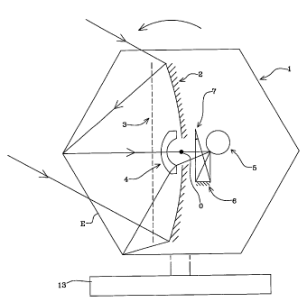
A first embodiment of this invention is illustrated in Figure 1. As shown in
Figure l, the primary drum or polygon 1 is supported in a support structure
indicated schematically at 13 for rotation about an axis O through the centre
of
the drum. The faces of the polygon consist of flat sheets of wire grid
polariser
that preferably transmit radiation having either vertical or horizontal
polarisation, (regarding the axis O as being vertical). Radiation from the
scene
(field of view) and having the correct polarisation passes through the sides
of
the polygon and falls onto a stationary concave mirror 2, which reflects the
radiation onto one facet (reference E, Figure 1) of the drum and which also
causes the radiation to converge towards a focus. The mirror 2 is ideally a
Mangin mirror to achieve good off axis performance. The polarisation of the
radiation reflected from the concave mirror 2 has been rotated by 90 °
(as
explained below) when it arrives back at the face E of the polygon 1 where it
is
now reflected back towards mirror 2. This reflected radiation, converging
towards a focus near the centre of the concave mirror, passes through a
diverging lens, such as a meniscus lens 4, before it reaches the last-
mentioned
focus, and then passes through a hole in the centre of the mirror 2; to the
second
rotating component, at some distance behind the mirror 2.
The 90° rotation of the direction of polarisation of the radiation
may be
achieved by placing a free-standing Faraday rotator 3 in front of the mirror
such
that on each passage of the radiation through the rotator the direction of
polarisation is rotated through 45°. Alternatively a quarter wave plate
may be
used in front of the concave mirror 2. In yet another configuration, the
metallic
surface of the mirror may be profiled to produce a 90° rotation of the
direction
of polarisation on reflection.
CA 02455682 2004-O1-23
WO 03/012524 PCT/GB02/03382
6
Figure 2 shows to a larger scale the radiation passing through the meniscus
lens
4 to strike the secondary rotating component, in the form of a polygon 5
having
outwardly presented reflective faces or facets defining the sides of the
polygon
5. The polygon 5 is mounted for rotation in said fixed structure for rotation
about an axis P parallel with the axis O, and is rotated in the same
rotational
sense as the polygon 1. The radiation reflected from this secondary polygon
may fall directly onto a fixed radiation receiver or sensor 7 or may, (as
shown),
be relayed by a further optical component such as a concave mirror 6 onto the
receiver 7. The lens 4 displaces the focal point of the mirror 2/facet E
combination to a position some distance behind the concave mirror 2 in order
to
provide space to accommodate the secondary drum 5 and receiver 7. The
meniscus lens illustrated also reduces, by a factor of two, the rate at which
the
axis onto which the radiation converges swings around relative to the
stationary
support structure as the primary drum rotates. That is to say, if, in Figure
2, r1
represents the ray passing along the respective primary drum facet axes at
time
t1 and r2 represents the ray passing along the axis of the same facet of the
primary drum at time t~ later than t1 and the angle, relative to the fixed
support
structure, between r1 and r2 immediately before passing through the lens 4 is
a,
the corresponding angle between rays r1 and r2 after passing through the lens
4
is a/2. Consequently, whereas if the lens 4 were omitted, the secondary drum
would have to rotate at half the angular rate of the primary drum to maintain
a
constant direction (relative to the fixed structure) of the axial ray r1 r2
reflected
from the secondary drum 5, and would have to have twice as many facets as the
primary drum, (in order to ensure that a geometrically similar relative
positioning of the primary and secondary drums was achieved every time that
the primary drum rotated through the angle necessary to move one face of the
primary drum into the position previously occupied by an adjacent face), with
CA 02455682 2004-O1-23
WO 03/012524 PCT/GB02/03382
7
the lens 4 as described, the secondary polygon is arranged to rotate at one
quarter of the speed of the primary polygon and has four times as many faces.
Thus, in this case, if the primary polygon has six faces, as illustrated, the
secondary polygon 5 will have 24 faces.
In an alternative arrangement, the curved surfaces of the meniscus lens may be
centred on the central, rotary axis of the primary drum 1, so that the
meniscus
lens does not change the rate at which the ray reflected from the respective
primary drum facet swings as the primary drum rotates, but still displaces the
focal point further behind the concave mirror 2, to allow room to accommodate
the further receiver assembly 5,6,7. In this case, the secondary polygon 5
rotates at one half of the speed of the primary polygon and has twice as many
faces.
The faces of the rotating polygon 1 are variously inclined with respect to the
axis of rotation O, so that the receiver 7 effectively "sees" during each line
scan
(i.e. during each 60° rotation of drum 1), a horizontal band of the
field of view
at a different elevation from that "seen" in adjacent line scans, (assuming
the
rotational axis of polygon 1 to be vertical in Figures 1 and 2).
Preferably, successive faces of the primary polygon (around the circumference
of the latter), are progressively inclined to the axis O so that a first face
might
be parallel with axis O, the second face inclined at 2° to axis O, the
third at 4°
to axis O and so on, with the sixth being inclined at 12° at axis O. As
a result,
the apparatus can generate a conventional, TV-type scanning raster as the drum
1 rotates. The faces of the secondary polygon 5 are correspondingly inclined
to
remove any deviation of the beam arriving at the receiver 7, i.e. so as to
ensure
CA 02455682 2004-O1-23
WO 03/012524 PCT/GB02/03382
g
that, despite such variations in inclination of the faces of the first polygon
l, the
beam of radiation arriving at receiver 7 does so with a fixed orientation.
The regions of the secondary polygon 5 where adjacent faces meet may be
blackened so as to provide a reference temperature for calibration purposes.
Whilst it is preferred to minimise the number of (expensive) receivers 7
required to achieve vertical scanning, (i.e. in a direction orthogonal to the
line
scan), by variation in the angle of inclination of the facets of drum 1
relative to
its rotary axis O, the picture information for each line of the scanned image
may instead be provided by a respective receiver 7 in a vertical array of such
receivers, each receiving radiation from a respective elevation in the field
of
view relative to fixed structure, (again assuming the apparatus to be arranged
so
that the rotational axis O of polygon 1 is vertical).
Preferably a combination of these two approaches is adopted, using an array of
a limited number of vertically spaced receivers 7, each receiving a few
(preferably adjacent) lines of the image, with the respective parts of the
image
"seen" by the different receivers being combined electronically to produce the
full "video" picture.
Referring to Figure 3, in a second embodiment of this invention, the hollow
rotary primary drum or polygon, (referenced 11), is located so that its
central,
axis 10 of rotation relative to fixed support structure 13 points directly
towards
the centre of the field of view of the apparatus, and a fixed mirror 9,
mounted
within the hollow rotating primary drum, is inclined at 45° with
respect to said
axis, so as to reflect, onto the reflecting facets of the primary drum 11,
radiation
entering the drum, from the field of view, from an open end of the drum. As
before, such radiation is focused by an optical element, which in Figure 3 is
a
CA 02455682 2004-O1-23
WO 03/012524 PCT/GB02/03382
9
fixed focusing lens 8 which is mounted within the primary drum and which is
located between the open end of the drum and the mirror 9. The axis of the
lens
8 is roughly parallel to the axis 10 about which the primary polygon or drum
11 rotates.
The fixed focusing lens 8, like the concave mirror 2 in the embodiment of
Figures 1 and 2, converges the incoming radiation towards a focus. This
converging radiation is reflected from the fixed plane mirror 9 onto that one
of
the reflective inwardly directed faces of the primary drum or polygon 11 which
is currently suitably positioned with respect to the mirror 10. Radiation
reflected from this face of the primary drum or polygon passes through a hole
in the centre of plane mirror 9 and is directed towards a focus close to the
axis
of rotation 10. In the same way as in the embodiment of Figures 1 and 2,
before
reaching the focus the radiation is relayed by a meniscus lens, (not shown in
Figure 3) onto a reflective secondary drum or polygon (not shown in Figure 3),
from whence it is reflected to the receivers (not shown in Figure 3), all
substantially as described in relation to Figures 1 and 2. The secondary drum
is
again rotated about an axis parallel with the rotary axis of the primary drum,
in
this case the axis 11, and is rotated in the same rotational sense as the
primary
polygon. The reflective faces of the primary polygon 11 and the secondary
polygon may be inclined with respect to their axes of rotation as in the first
embodiment, to achieve scanning in the direction orthogonal to the line scan
direction as the drum 11 rotates.
In yet another embodiment, illustrated in Figure 4, the rotary hollow primary
drum or polygon is again located so that its central, rotary axis 10 points
directly towards the centre of the field of view of the apparatus, and a fixed
mirror 9, inclined at 45° with respect to said axis, is again mounted
within the
hollow rotating primary drum, so as to reflect, onto the reflecting faces of
the
CA 02455682 2004-O1-23
WO 03/012524 PCT/GB02/03382
primary drum, radiation entering the drum, from the field of view, from an
open
end of the drum. Again, the fixed mirror 9 reflects the incoming radiation
onto
whichever of the reflective faces of the primary drum is temporarily in the
right
position to receive such reflected radiation and the reflective face in
question,
as before, reflects that radiation back towards the fixed mirror. In the
embodiment illustrated in Figure 4, the reflective faces or "facets" of the
primary drum or polygon are concave reflectors or "mirrors" 12 which are used
to focus the radiation from the scene/field-of view towards a position close
to
the axis of rotation 10 of the primary polygon as illustrated in Figure 4,
but, as
in the preceding embodiments, this radiation passes, eg. via a meniscus lens,
(not shown), through a central hole in the mirror 9, and onto a further
receiving
assembly (not shown) of the same form as that described with reference to
Figures l and 2, and thus comprising a similarly arranged secondary drum or
polygon (again rotating about an axis parallel with axis 10 and in the same
rotational sense as the primary polygon), and radiation receiver or array of
such
receivers.
In the drawings, the angles through which the light beams are shown as being
reflected are significantly exaggerated for purposes of illustration. In
practice,
the width of the scan, in terms of angle about the rotational axis of the
first
drum (primary drum) i.e. the horizontal extent of the field of view,(where
this
axis is vertical) is of the order of 20°. Thus for example in the
embodiments of
Figures l and 2, assuming the central "line of sight" of the scanning
apparatus
to pass orthogonally through the middle of one wall of the primary polygon in
one position of the latter at a particular point in time, the corresponding
line
scan for radiation reflected by the mirror onto that particular wall of the
primary
drum might commence when the drum is still 10 ° away from that
orthogonal
position and terminate when the drum is some 10° past that orthogonal
position.
CA 02455682 2004-O1-23
WO 03/012524 PCT/GB02/03382
11
Whilst, in the drawings, the primary drum or polygon has been represented as
being hexagonal, it should be appreciated that it may be in the form of a
polygon with a greater or lesser number of sides, for example it may be of
triangular, square or pentagonal form, (with the secondary drum or polygon
being, of course, appropriately configured).
As will be appreciated from the above, the invention provides a means of
providing, at minimum expense, a two-dimensional "view" of a "scene" viewed
in microwave, mm-wave or infrared radiation. Furthermore, the preferred
forms of apparatus in accordance with the invention allow such a view to be
obtained without excessive duplication of expensive receiving elements and
without large and prohibitively expensive lens elements. The preferred
embodiments of the invention also offer the advantage of compactness.