Note: Descriptions are shown in the official language in which they were submitted.
CA 02455739 2004-O1-21
t a a'.AT ~~SSI~~~ I~~ ~~~~~~ F~~ ~~~ ~T~~~ ~F
DISSIP~TII~1C~ A'I~ F~~M A M~~I~T~F'~'~,I~
Field of the Invention
[0001] The present invention relates generally to an injection molding
apparatus and, in particular, to a heat dissipation device for and a method of
dissipating heat from a manifold.
background ~f The ~nventic~n
[0002] As is well known in the art, hot runner injection molding systems
include a manifold for conveying pressurized melt from an inlet to one or
more manifold outlets. Each manifold outlet leads to a nozzle, which, in turn,
extends to a gate of an injection mold cavity. ~~ianifolds have various
configurations, depending upon the number and arrangement of the nozzles
and the corresponding injection mold cavities.
[0003] It is known to neat the manifold in order tc maintain a desired
temperature distribution throughout the manifold. Means of heating manifolds
include integrally casting or brazing an electrical heating element into t:he
manifold, as described in ILS. F°at. No. 4,688,622 to Gellert and ~T.S.
Pat. No.
4,648,546 to Gellert, respectively. The heating element may also be
mechanically joined to the manifold by pressing the element into the manifold
to create an interference, friction or defog~nation fit. Alternatively,
thermal
spraying techniques may be employed to bond the heating element to the
manifold. Further, a cartridge heater may be cast in the manifold, as
disclosed
in I=T.S. Pat. No. 4,439,~I5 to Gellert o~- a plate heater may be positioned
adjacent the manifold to provide heat thereto, as disclosed in U.S. Pat. No.
6,447,283 to Gellert.
[0004) Deferring to Figure l, a typical prior art manifold is generally
indicated
at I00. The manifold 100 includes a manifold channel 102 and an integrated
heating element 104. Pleating of the manifold I00 by the heating element 104
is generally not uniform. None of the prior art manifold heating techniques
CA 02455739 2004-O1-21
-2-
provide an even heat distribution throughout the manifold. Hot spots occur at
locations where the watt density is high and there is little or no contact
with
the surrounding mold plates. It is therefore desirable to remove heat from the
manifold at these hot spot locations. As is clear from the layout of the
heating
element, the watt density varies from one manifold location to the next.
Certain locations, near the nozzles for example, receive more heat because
there is a greater length of heating element concentrated an those regions.
Increasing the amount of heat generated at a particular manifold location by
providing additional heating element length is generally not a practical
solution. The heating element can only withstand a certain bend radius and
must avoid connection points to other injection molding apparatus components
such as the nozzles and the manifold backing plate. The hot/cold transition of
the heating element, which is located near the entry and exit point of the
heating element, is an example of a location where less heat is generated.
[0005] In an injection molding apparatus, contact between the manifold and
the mold plates results in heat loss from the manifold. The location of
cooling
lines in the mold plates can influence the amount of heat loss from the
manifold. Generally, the closer the cooling lines are to the ananifold, the
greater the heat loss from the manifold. Contact between the manifold and the
nozzles may cause the manifold to either lose heat or gain heat depending on
the particular application.
[0006] The temperature of the manifold is further influenced by the melt
stream itself. For example, the temperature of the melt tends to be higher at
locations where the melt experiences high shear stress, such as at bends in
the
manifold channel. Different types of melt will also influence the manifold
temperature in different days.
[0007] An uneven distribution of heat in the manifold causes the temperature
of the melt entering the nozzles to vary slightly from one nozzle to the next.
Any variation in the temperature of the melt entering each of the nozzles can
adversely affect the quality of the molded products being produced by the
injection molding process. ~Iith the increased use of more difficult to mold
CA 02455739 2004-O1-21
_ J _
plastics materials, the melt must be maintained within narrower and narrower
temperature ranges. if the temperature rises too high, degradation of the melt
will result, and if the temperature drops too low, the melt will clog in the
system and produce an unacceptable product. Both extremes can necessitate
the injection molding apparatus being shut down and cleaned out, which can
cause a very costly Loss a~ production.
[000] An uneven distribution of heat in the manifold has a further
disadvantage in that the manifold is subjected to high stress due to
continuaus
cycling between higher and lower temperatures. 'This can result in a shorter
manifold life and increased downtime for the injection molding apparatus.
[0009] It is therefore an object of the present invention to provide a heat
dissipation device for a manifold that obviates or mitigates at least one of
the
above disadvantages.
Summary ~f 'The Invention
[0010] According to an aspect of the present invention there is provided an
injection molding apparatus comprising:
a hot runner manifold;
a heater coupled to said manifold; and
a heat dissipation device, having a first end coupled to said manifold
between said manifold and a cooler member, said cooler member having a
lower temperature than said manifold;
wherein said heat dissipation device thermally expands and contacts
said cooler member when a temperature of said manifold at said pre-
determined location increases above a predetermined temperature.
[0011] According to another aspect of the present invention there is provided
an injection molding apparatus comprising:
a manifold;
a heater coupled to said manifold; and
CA 02455739 2004-O1-21
_ df _
a heat dissipation device coupled to said manifold, said heat dissipation
device having a first orientation when said manifold has a temperature below a
predetermined temperature and a second orientation when said manifold has a
temperature greater than a predetermined temperature, wherein said first and
second orientations differ in that said second orientation contacts an
adjacent
cooler member.
[0012] According to another aspect of the present invention there is provided
a method of locally cooling a manifold of an injection molding apparatus
comprising:
measuring the temperature of said manifold;
identifying high temperature locations on a surface of said manifold;
coupling a first end of a heat dissipation device to said surface of said
manifold at said high temperature locatiorAS;
positioning a second end of said heat dissipation device such that
thermal expansion causes said second end to come into contact with a cooler
member when the temperature of said surface at said high temperature
locations increases to a predetermined temperature; and
heating said manifold surface to a temperature greater than said
predetermined temperature.
[0013] According to another aspect of the present invention there is provided
a heat dissipation device for use with a hot runner manifold apparatus,
comprising:
a first end, thermally coupled with a hot runner manifold, a second and
and one or more thermally conductive layers,
wherein said second end of said heat dissipation device thermally
expands and contacts a cooler portion of said manifold apparatus only at
temperatures above a predetermined temperature.
[0014] According to another aspect of the present invention there is provided
a method of dissipating heat from a manifold of an injection molding
apparatus, comprising:
providing an injection molding apparatus including a manifold;
CA 02455739 2004-O1-21
-5-
providing a tnani.fold backing plate adjacent but not contacting said
manifold;
providing at least one heat dissipation device having a first end and a
second end;
coupling said first end to said manifold;
directing heat away from said manifold by allowing said heat
dissipation device to thermally expand and contact said manifold backing plate
when said manifold temperature increases beyond a predetermined
temperature.
[0015] The present invention p~°ovides advantages in that the
occurrence of hot
spots in the manifold is reduced and the temperature distribution throughout
the manifold is more even.
Brief Description ~f '~'he Drawings
[0016] Embodiments of the present invention will now be described more
fully with reference to the accompanying drawings in which:
[0017] Figure 1 is a top view of a prior art manifold;
[0015] Figure 2 is a side sectional view an injection molding apparatus in
accordance with an embodiment of the present invention;
[0019) Figure 3 is a side sectional view of injection molding apparatus in
accordance with another embodiment of the present invention;
[0020] Figure 4A is a top view of a heat dissipation device of the present
invention;
[0021] Figure 4B is a cross-sections( view taken along line A-A of Figure 4A;
[0022] Figure 4C is a perspective view of the heat dissipation device of
Figure
4A;
[0023] Figure 5 is alternate cross-sectional view taken along line A-A of the
heat dissipation device of Figure 4A;
[0024] Figure 6 is an alternate cross-sectional 'view taken along line A-A of
the heat dissipation device of Figure 4A;
CA 02455739 2004-O1-21
_6-
[0025] Figure 7A is a top view of an alternate heat dissipation device of the
present invention;
[0026] Figure 7B is a cross-sectional view taken along line B-B of Figure 7A;
[0027] Figure 7C is a perspective view of the heat dissipation device of
Figure
7A;
[0028] Figure 8 is alternate cross-sectional view taken along line B-B of the
heat dissipation device of Figure 7A; and
[0029] Figure ~3 is an alternate cross-sectional view taken along line B-B of
the heat dissipation device of Figure 7A.
Detailed Description ~f The Preferred embodiments
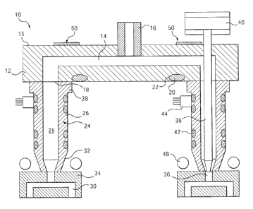
[0030] Referring now to Figure 2, an injection molding apparatus is generally
indicated by reference numeral i0. The injection molding apparatus 10
comprises a manifold 12 having a manifold channel 14 extending
therethrough. A manifold bushing I6 is located at an inlet of the manifold
channel 14 to receive a melt stream of moldable material from a machine
nozzle (not shown) and vo deliver the melt stream to manifold outlets '18. A
heating element 20 is rested in a groove 22 that extends through the manifold
12 to maintain the melt stream at a desired temperature.
[0031] Nozzles 24 are located between the manifold ? 2 and respective mold
cavities 30, v~~hich are formed in mold cavity plates 34. Each nozzle 24
includes a nozzle body 26 having a nozzle head 28 and a nozzle tip 32. A
nozzle channel 25 extends through the nozzle 24 for delivering the melt stream
from each manifold oictlet 18 to the corresponding mold cavity 30.
[0032] Mold gates 3G are provided at the entrance to the mold cavities 30.
The mold gates 3G are selectively openable to allow melt to be delivered to
the
mold cavities 30. The nozzles 24 may be thermal gated (shown on the left of
Figure 2) or valve gated (shown on the right of Figure 2). The valve gated
nozzles 24 include a valve pin 38 that is driven by a valve piston 40. Each
CA 02455739 2004-O1-21
valve pin 38 is selectively movable to open and close the respective mold gate
3G.
[0033] Each nozzle 24 -is further providod with a heater 42, which helps to
maintain the melt stream at a desired temperature as it passes through the
nozzle 24. The heater 42 is powered through an electrical connector 44 that is
in communication with a power source (not shown). Cooling channels 46 are
located adjacent the mold cavities 30 in order to cool the melt therein. feat
dissipation devices 50 are coupled to an upper surface 15 of the manifold 12
at
the locations shown.
[0034] Another embodiment of an injection molding apparatus l0a is shown
in Figure 3. In this embodiment, the manifold is a bridging manifold I2a,
which is comprised of a main manifold ' 1 and sub-manifolds 13. The main
manifold 11 includes a main manifold channel 48 that is in communication
with sub-manifold channels 14a of the sub-manifolds 13. A manifold bushing
16a is located at an inle~ of the main manifold channel 48 to receive a melt
stream of moldable material from a machine nozzle (not shown). The sub-
manifolds 13 are coupled to the main manifold 11 by manifold melt links 70,
which allow melt to flow from the main manifold channel 48 into the sub-
manifold channels 14a. The sub-manifolds 13 are positioned in the injection
molding apparatus 10a relative to mold plate 72 by scab-manifold locating
rings 74. The main manifold 1 I is separated from the manifold backing plate
76 by spacers 80 and located relative to the mold plate 72 by a main manifold
locating ring 82. Cooling channels 4Ga extend through the mold plates 72 and
7G.
[0035] Nozzles 24a are coupled to the sub-manifolds I3 by bolts 84. Each
nozzle 24a includes a nozzle channel 25a that extends therethrough. The
nozzles 24a are located between the sub-manifold 13 and respective mold
cavities (not shown). In operation, the injection molding apparatus l0a is
heated up from the cold condition, in which all of tlae components are at
generally the same ambient temperature. The manifold I2a, which includes
the main manifold 11 and the sub-manifolds I3, and 1:11e nozzle 24a are then
CA 02455739 2004-O1-21
_ 8 _
maintained at their respective temperatures. belt is injected from the machine
nozzle into the manifold bushing 16a of the manifold 12a. The melt flows
through the main manifold channel 48, through the manifold melt links 70,
through the sub-manifold channels 14a and into the nozzle channels 25a and is
injected into the mold cavities. The melt is then coated in the mold cavities
in
order to produce finishes 3nolded parts.
[0036] Heat dissipation devices 50, similar to those shown in Figure 2, are
shown in Figure 3. Heat dissipation devices 50 are secured at a first end 53
to
the upper suuface 15a of the main manifold 12a, such as by fasteners 51 or
another method apparent to one skilled in the art, at or~° or more hot
spots on
manifold 12a. Hot spots are locations on the manifold 12a that reach a
temperature that is above a desired, ,pre-determined temperature during .
operation of the injection molding apparatus 10a. The hot spots are identified
by methods that are well known in the art, such as simulation of an operating
manifold using finite element analysis or measurement of the temperature of
an operating manifold using an infrared camera.
[0037] As shown in Figure 4A a heat dissipation device 50 is a generally
rectangular plate. However, heat dissipation device 50 may be a plate that is
shaped other than generally rectangular. her example, heat dissipation device
50 may be oval, arcuate shaped, or another polygonal ar non-polygonal shape.
Figure 4B is a cross section taken along fine A-A of Figure 4A. As seen in
Figure 4B heat dissipation device 50 is made from a single piece of a highly
thermally conductive traaterial, with a high coefficient of thermal expansion.
These materials may be copper, copper alloys, almninum, and aluminum
alloys.
[0038] Preferably, heat dissipation device 50 lZas a second end 55 that is
curved, as shown in Figure 4C. Once positioned between a manifold backing
plate 76 and a manifold 12, second end 55 is curved toward manifold backing
plate 76 just enough that it is close to but does not contact manifold backing
plate 76, when cool. As heat dissipation device 50 draws heat from manifold
12, heat dissipation device 50 begins to expand due to thermal expansion, as
CA 02455739 2004-O1-21
-9-
shown in shadow in Figure 4C. Based on the coefficient of thermal
expansion, one skilled in the art may select the correct material, size and
length of heat dissipation device 50, such that it will expand to bring second
end 55 into contact with manifald backing plate 76 when the temperature of
manifold 12 reaches a desired temperature. Once second end SS contacts the
cold manifold backing plate 76, heat will be transfei'red to manifold backing
plate 76 and away from the hot spot of manifold 12, cooling and lowering the
temperature of manifold 12 at the location opposite first end 53 of heat
dissipation device 50.
[0039] Once the temperature at the hot spot falls below the pre-determined
temperature, heat dissipation device 50 will cool and shrink. away from
manifold backing plate 76. If the loot spot regenerates, heat dissipation
device
50 will again thermally expand and the cycle will repeat, creating a
temperature actuating heat dissipation device 50.
[0040] In another embodiment of the present invention, heat dissipation
device 50 may require no contact to the manifold backing plate 76. Instead,
the excessive heat at hot spots on manifold 12 can be transferred to the air
between manifold backin;~ plate 76 and manifold 12. I~owever, second end 55
of heat dissipation device SO must be positioned so that even with thermal
expansion the second eczd Sj does not contact manifold. backing plate 76.
[0041] Figure 5 shows an alternative cross section along line A-A of hf;at
dissipation device 50 from Figure 4A. In this case, heat dissipation device
SOa
of Figure 5 includes a first layer 56, which contacts the upper surface 15a of
manifold 12, and a second layer 58 adjacent to first lay 56. First layer 56
and
second layer 58 are coupled to one anothej- by brazing, welding, soldering or
a
high temperature adhesive. First layer 56 is comprised of a material having a
high coefficient of expansion and second layer 58 is comprised of a material
having a low coefficient of expansion.
[0042] Suitable materials for first layer 56 include copper, copper alloys,
aluminum, and aluminum alloys. Suitable materials for second layer 58
include titanium, titanium alloys, stainless steels, iron alloys, ceramics and
CA 02455739 2004-O1-21
fiberglass. In a preferred embodiment, heat dissipation device 50a is bi-
metallic with a copper or copper alloy first layer 56 and a nickel second
layer
58. It will be appreciated by persons skilled in the art that any combination
of
materials can be used for heat dissipation device 50a, provided that first
layer
56 has a higher coefficient of thermal expansion than second layer 58.
[004] The thickness of both first and second layers 56, 58 is selected based
on the desired thermal response characteristics for a particular application.
The thickness of the layers 56, 58 is generally in the .range of 0.01 inches
to
0.125 inches.
[0044] Heat dissipation device 50a need not be initially curved like heat
dissipation device 50 of Figure 4~. Instead, heat dissipation device 50a moves
between a generally flat position, shown at 50a in Figure '~, in which the
heat
dissipation device 50a lies against upper surface 15a of manifold 12, and a
curved position, similar- to that shown at 50 in Figure 3, in which a second
end
55a of heat dissipation device 50a curves away from manifold 12. As
injection molding apparatus l0a is heated up from a cold condition, the
temperature of manifold 12 increases, particularly at the previously
identified
hot spots, and first layer 56 and second layer 58 of heat dissipation device
50a
expand due to thermal expansion. I-Iowever, second layex 58 expands at a
slower rate than first layer 56. The difference in rates of expansion between
first layer 56 and second layer 589 makes heat dissipation device 50a curl.
[0045] As it curls, second end 55a of heat dissipation device 50a curves away
from manifold upper su3-face 15a. When the temperature of the hot spots has
increased beyond a pre-determined value, the curved heat dissipation device
50a contacts manifold backing plate 7~. Heat is then transferred from
manifold 12 to manifold backing plate 76 via heat dissipation device 50a. The
temperature at the hot spots reduces in response to the heat lost to manifold
backing plate 76. As the temperature reduces, first layer 56 and second layer
58 shrink, also at different rates. ~nce the temperature falls below a pre-
determined temperature, second end 55 shrinks enough to lose contact with
manifold backing plate 7b, arid heat dissipation device 50a falls back to a
CA 02455739 2004-O1-21
-11-
generally flat position. The heat dissipation device 50a cycles between a
generally flat position and a curved position to regulate the temperature of
manifold hot spots.
[0046] Figure 6 shows an alternative cross section along line A-A of heat
dissipation device 50 from Figure 4A. In this case, heat dissipation device
50b
includes an outer layer 60 located adjacent second layer 58 of heat
dissipation
device 50a of Figure 5. Outer layer 60 is secured to second layer 58 by
brazing, soldering, welding or a high temperatuxe adhesive. Outer layer 60 is
generally thinner than heat dissipation device 50a so as not to hinder the
curving motion discussed above created by the thermal expansion rate
difference between first layer 56 and second layer 58. Outer layer 60 is
comprised of a material having a high rate of thermal conductivity. Suitable
outer layer 60 materials include copper, copper alloys, aluminum, and
aluminum alloys. Outer layer 60 and first layer 56 ma~° be the same
material.
Outer layer 60 may, alternatively, be a material completely separate from heat
dissipation device SOa.
[0047] In operation, hea.lt dissipation device 50b operates as previously
described for heat dissipation device 50a. As heat dissipation device 50a
moves away from upper surface 15a of nanifold 12, outer layer 60 moves
with it. Both heat dissipation device 50a and outer layer 60 continue to curve
away from manifold 12 until second end 55b of outer layer 60 contacts
manifold backing plate 76. 'then in contact, secand layer 58 acts as
insulation between first layer 56 and outer layer 60, thus operating as a
damper
so that heat loss from manifold 12 via heat dissipation device 50b is gradual.
This ensures that heat dissipation device 50b does not oscillate too xapidly
between the curved and generally flat positions.
[0048] Referring to Figure 7A, another embodiment of a heat dissipation
device 62 is shown. The construction and operation of beat dissipation device
62 is similar to that of heat dissipation device 50. However, instead of being
a
generally rectangular plate, heat dissipation device 62 includes a plurality
of
fins 52 e~ctending from a base 54. Figure 7B is a cross section taken along
line
CA 02455739 2004-O1-21
_12_
B-B of Figure 7A. As seen in Figure 7B, heat dissipation device 62 is made
from a single piece of a highly thermally conductive material, with a high
coefficient of thermal expansion. These materials may be copper, copper
alloys, aluminum, and aluminum alloys.
[0049] Heat dissipation device 62 operates identically to heat dissipation
device 50. Fins 52 of heat dissipation device 62 are curved, as shown in
Figure 7C and positioned so that fins 52 are close to but do not contact
manifold backing plate 76, when cool. When heated, thermal expansion
causes fins 52 to expand to contact manifold backing plate 76, as shown in
shadow in Figure 7C. When enough heat has transferred from manifold 12 to
manifold backing plate 76 to reduce the temperature of manifold 12, heat
dissipation device 62 has cooled enough that fins 52 shrink away from
manifold backing plate 76. The distance that the fins 52 move can be
controlled based on selection of materials and selection of a fin length.
[0050] Similar to heat dissipatian device 50, it may be desirable to dissipate
heat from the manifold .12 without heat dissipation device 62 having direct
contact with manifold hacking plate 76. fn this case, particular
characteristic
of the material and fin length are selected so that the fins 52 do not contact
manifold backing plate 76 even with thermal expansion. In this case, more
heat will be dissipated from heat dissipation device 62 than heat dissipation
device 50 due to the increased surface area created by fins 52 of heat
dissipation device 62.
[0051] Figure 8 shows an alternative cross section along line B-B of heat
dissipation device 62 from Figure 7A. In this case, heat dissipation device
62a
of Figure 8 includes a fiat Iayer 64, which contacts upper surface 15a of
manifold 12, and a second layer 66 adjacent to first layer 64. First layer 64
is
comprised of a material having a higherv coefficient of expansion than the
material of second layer 65. Heat dissipation device 62a of Figure 8 operates
in the same manner as heat dissipation device 50a of Figure 5. Fins 52 curl
away from manifold 12 due to the difference in thermal expansion rates of
first and second layers 64, 66 until fins 52, contact manifold backing plate
76
CA 02455739 2004-O1-21
-13-
at a predetermined temperature. When the temperature of manifold 12 falls to
below the predetermined temperature, the fins uncurl and move back towards
a relatively flat position. The cycle continues as the temperature of manifold
12 fluctuates above and below the predetermined temperature.
[0052] Figure 9 shows an alternative cross section along line B-B of heat
dissipation device 62 frown Figure 7A. In this case, heat dissipation device
62b
includes an outer layer 68 located adjacent second layer 66 of heat
dissipation
device 62a of Figure 8. Outer layer 68 operates identically to outer layer 60
of
heat dissipation device SOb. As heat dissipation device 62a curls due to the
different thermal expansion rates of first and second layers 64, 66, outer
layer
68 contacts manifold backing plate 76. Thus, second layer 66 acts as
insulation between the higher thermal conductive materials of first layer 64
and outer layer 68. In another embodiment, fins 52 of outer layer 68, may be
corrugated.
[0053] Because each heat dissipation device operates independently and is
heat-actuating, a heat dissipation device is useful for regulating hot spots
of
any temperature based on the particular selection of materials and
construction. Further, several heat dissipation devices may be used at
different locations on manifold 12 to regulate the temperature of different
hot
spots. For example, if one hot spot is at a higher temperature than another.,
a
heat dissipation device at that spot will curve away from the surface more
quickly to contact manifold backing plate 76 and remain in contact with the
manifold backing plate 76 for a longer period of time than a heat dissipation
device positioned adjacent a lower temperature hot spot, which will dissipate
a
larger amount of heat from the higher temperature spot. The heat-actuating
behavior of a heat dissipation device of the present invention allows it to
perform differently in response to each hot spot.
[0054] It will be appreciated that any heat dissipation device of the present
invention may be sized to cover any area on manifold 12. In addition, a heat
dissipation device is not limited to being coupled to upper surface lSa of
manifold 12. A heat dissipation device may be coupled to manifold '12 at any
CA 02455739 2004-O1-21
- 14-
location where it is desirable to dissipate heat, In a bridging manifold, such
as
that of Fig. 3, a heat dissipation device of the present invention may be
coupled to the main manifold 11, the sub-manifolds 13, or both. A heat
dissipation device may further be coupled to any location in an inaection
molding apparatus where local heat dissipation is desired. It will further be
appreciated by a person skilled in the art that a heat dissipation device may
be
used with any type of manifold that is heated by any type of ~~nanifold
heating
arrangement.
[0055] The many features and advantages of the invention are apparent from
the detailed specification and, thus, it is intended by the appended claims to
cover all such features and advantages of the invention that fall within the
true
spirit and scope of the invention. Further, since numerous modifications and
changes will be readily apparent to one skilled in the art, it is not desired
to
limit the invention to the exact construction and operation illustrated and
described by the text, figures or claims herein, and al:l suitable
modifications
and equivalents are to be considered to fall within the scope of the
invention.