Language selection

Search

Patent 2456228 Summary

Third-party information liability

Some of the information on this Web page has been provided by external sources. The Government of Canada is not responsible for the accuracy, reliability or currency of the information supplied by external sources. Users wishing to rely upon this information should consult directly with the source of the information. Content provided by external sources is not subject to official languages, privacy and accessibility requirements.

Claims and Abstract availability

Any discrepancies in the text and image of the Claims and Abstract are due to differing posting times. Text of the Claims and Abstract are posted:

  • At the time the application is open to public inspection;
  • At the time of issue of the patent (grant).
(12) Patent Application: (11) CA 2456228
(54) English Title: TENT
(54) French Title: TENTE
Status: Deemed Abandoned and Beyond the Period of Reinstatement - Pending Response to Notice of Disregarded Communication
Bibliographic Data
(51) International Patent Classification (IPC):
  • E04H 15/32 (2006.01)
  • E04H 15/00 (2006.01)
  • E04H 15/28 (2006.01)
(72) Inventors :
  • WU, CHUNG-CHENG (Taiwan, Province of China)
(73) Owners :
  • CHUNG-CHENG WU
(71) Applicants :
  • CHUNG-CHENG WU (Taiwan, Province of China)
(74) Agent: KIRBY EADES GALE BAKER
(74) Associate agent:
(45) Issued:
(22) Filed Date: 2004-01-26
(41) Open to Public Inspection: 2005-07-26
Examination requested: 2004-01-26
Availability of licence: N/A
Dedicated to the Public: N/A
(25) Language of filing: English

Patent Cooperation Treaty (PCT): No

(30) Application Priority Data: None

Abstracts

English Abstract


A tent comprising a shaft, a protective cover, a handle and a plurality number
of
supporting ribs; the upper, lower shaft design and the supporting ribs is easy
for storage; a
running ring below the runner is on the upper shaft, two ropes connecting to
the runner
and running ring respectively stretch out from a cap and connect to an opening
ring and a
closing ring respectively as the open and close switches, a zipper door is on
one side of
the protective cover, a ground mats covering ground stretches from the bottom
of the
protective cover, the ground mats has a tri-directional zipper.


Claims

Note: Claims are shown in the official language in which they were submitted.

CLAIMS
What is claimed is:
1. A tent comprising:
a shaft consists of a upper shaft and lower shaft, an indentation is on said
upper shaft,
a stopper protruding out on said upper shaft is on said indentation, a fixing
ring, a runner
and a running ring are on said upper shaft, said fixing ring is on top of said
upper shaft,
said runner is beneath said fixing ring, said running ring is below said
runner, two ropes
connecting to said runner and said running ring respectively stretch out from
a cap on top
of said upper shaft and connect to an opening ring and a closing ring
respectively;
a protective cover with a center hole wraps said upper shaft from top and is
fixed
onto said fixing ring by said cap, said protective cover has the same amount
of tip cover
corresponding to each tip of the supporting rib, also has a viscous fastening
part
corresponding to each of the rib;
a handle wraps around said cap and is fastened on the top of said upper shaft;
said supporting ribs consists of a plurality number of said ribs and said
stretchers, the
two ends of said rib are connected to said fixing ring and said tip cover of
said protective
cover respectively, the two ends of said stretcher are connected to
corresponding said rib
and the brim of said runner respectively.
2. The tent recited in claim 1, wherein the total length of said shaft after
assembly of said
upper and said lower shafts is slightly longer than said supporting ribs.
7

3. The tent recited in claim 1, wherein a connector is on the proper location
of said rib to
make said rib fold outward.
4. The tent recited in claim 3, wherein a zipper door is on one side of said
protective
cover, a ground mats covering ground with the size of opened said supporting
ribs
stretches from the bottom of said zipper door, said ground mats has a tri-
directional
zipper.
8

Description

Note: Descriptions are shown in the official language in which they were submitted.


CA 02456228 2004-O1-26
TENT
BACKGROUND OF THE INDENTION
I. Field of the Invention
This invention relates generally to a tent and, more specifically, to a tent
in umbrella
structure with a switch that is easy to open and convenient to store.
II. Description of the Prior Art
Heretofore, it is known that tents are for people to rest or sleep in the
evening while
camping outdoors, or a temporary shelter to avoid insects and snakes.
The structure of known tents a, referring to FI~'r 1, is to have several
supporting
poles b form a space; then apply a cover c externally, four sides of the cover
c is stabled
on ground with nails or ropes to resist wind and rain.
However in some special occasions, fishing or mountain climbing for example,
the
camping location might change as needed, the structure of the known tents is
too large
and not easy to install and store; some tents have springs as supporting poles
for easy
recovery, however such supporting poles are with elasticity and not able to
resist heavy
wind for protection.
1

CA 02456228 2004-O1-26
SUMMARY OF THE INVENTION
It is therefore a primary object of the invention to provide a tent that is
easy to install
and convenient to recovery, store.
In .order to achieve the objective set forth, a tent in accordance with the
present
invention comprises a shaft, a protective cover, a handle and a plurality
number of
supporting ribs. The shaft consists of a upper shaft and a lower shaft, an
indentation is on
the upper shaft, a stopper protruding out on the upper shaft is on the
indentation; a fixing
ring, a runner and a running ring are on the upper shaft; the fixing ring is
on top of the
upper shaft, the runner is beneath the fixing ring, the running ring is below
the runner:
The protective cover with a center hole wraps the upper shaft from top and is
fixed onto
the fixing ring by a cap; the protective cover has the same amount of tip
cover
corresponding to each tip of the supporting rib; two ropes connecting to the
runner and
running ring respectively stretch out from the cap on top of the upper shaft
.and connect to
an opening ring and a closing ring respectively; a zipper door is on one side
of the
protective cover, a ground mats covering ground stretches from the bottom of
the zipper
door, the ground mats has a tri-directional zipper
Based on the structure described above, the physical size and height of the
present
invention depend on the moving length of the runner on the shaft for the
maximum inner
space and easy for storage; therefore the design of the shaft is subdivided
into upper and
2

CA 02456228 2004-O1-26
lower portion; a connector is on the proper location of the rib. When. users
pull the runner
up along the shaft and pull the ribs and stretchers open simultaneously, the
'protective
cover is propped up; the runner is fixed by the stopper to maintain the
present invention in
open state; when users intend to recover the present invention, they can pull
the closing
ring connecting to the running ring and have the running ring move up along
the upper
shaft, the running ring pushes the stopper down into the indentation, the
runner moves
down by the push from the supporting ribs to have the supporting ribs close
inward.
Based on the structure described above, users can pull the opening ring to
prop up
the supporting ribs, then remove the lower shaft and close the tri-directional
zipper; while
recovery, users unzip the tri-directional zipper, connect the upper and lower
shaft together,
then pull the closing ring to close the supporting ribs.
BRIEF DESCRIPTION OF THE DRAi~VINGS
The accomplishment of the above-mentioned object of the present invention will
become apparent from the following description and its accompanying drawings
which
disclose illustrative an embodiment of the present invention, and are as
follows:
FIG 1 is a perspective view of the prior art;
FIG 2 is across-sectional view of the present invention;
3

CA 02456228 2004-O1-26
FIG 3 is a cross-sectional view of a further embodiment of the present
invention;
FIG 4A is an application view of the present invention;
FIG 4B is another application view of the present invention;
FIG 4C is a perspective view of a further embodiment of the present invention;
FIG S is a perspective view of the present invention.
DESCRIPTION OF THE PREFERRED EMBODIMENT
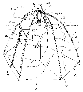
Referring to FIG 2 and FIG 3, the present invention is composed of a shaft 10,
a
protective cover 20, a handle 30 and a plurality number of supporting ribs 40.
The
functions of each component are described below:
The shaft IO consists of a upper shaft 11 and a lower shaft 12, the total
length of the
shaft 10 after assembly is slightly longer than the supporting ribs 40; an
indentation 11 a is
on the upper shaft 11, a stopper llal protruding out on the upper shaft 11 is
on the
indentation 11 a; a fixing ring 11 b, a runner 11 c and a running ring 11 d
are on the upper
shaft 11; the fixing ring 11 b is on top of the upper shaft 11, the runner 11
c is beneath the
fixing ring 11 b, the running ring I 1 d is below the runner 11 c; two ropes
11 a connecting to
the runner 11 c and running ring I 1 d respectively stretch out from the cap 1
l f on top of the
upper shaft 11 and connect to an opening ring l lcl and a closing ring l ldl
respectively:
The protective cover 20 is in polygon shape with equal sides and topped with a
4

CA 02456228 2004-O1-26
center hole 21, the protective cover 20 wraps the upper shaft 11 from top and
is fixed onto
the fixing ring 11 b by the cap 11 f; the protective cover 20 has the same
amount of tip
cover 22 corresponding to each tip of the supporting rib 40, also has a
viscous fastening
part 23 corresponding to each of the rib 41; a zipper door 24 is on one side
of the
protective cover 20, a ground mats 25 covering ground with the size of the
opened
supporting ribs 40 stretches from the bottom of the zipper door 24; the ground
mats 25
has a tri-directional zipper 26.
The handle 30 wraps around the cap 11 f and is fastened on the top of the
upper shaft
11.
The supporting ribs 40 consists of a plurality number of ribs 41 and
stretchers 42, a
connector 41 a is on the proper location of the rib 41 to make the rib 41 fold
outward; the
two ends of the rib 41 are connected to the fixing ring 11b and the tip cover
22 of the
protective cover 20 respectively; the two ends of the stretcher 42 are
connected to the
corresponding rib 41 and the brim of the runner 11 c respectively.
'15 Referring to FIG 4A, FIG 4B and FIG 4C and based on the structure
described above,
when users intend to open the present invention, they pull the opening ring 11
c 1
connecting to the runner 11 c to have the runner 11 c move up albng the upper
and lower
shaft 11, 12 first, the stretchers 42 are pulled upward along with the runner
11 c, the ribs
41 are also stretched open to prop the protective cover 20 open; the runner 11
c is fixed by
the stopper llal to maintain the present invention in open state; users can
split the upper
5

CA 02456228 2004-O1-26
and lower shaft 11, 12 and pull the tri-directional zipper 26 to have the
protective cover
20 in enclosed condition; users can come in and out through the zipper doors
24: When
users intend to recover the present invention, they can unzip the tri-
directional zipper 26
to let the protective cover 20 in loose state, connect the upper and lower
shaft 11, 12
together to form a rail for the running ring 11 d, users then pull the closing
ring 11 d l
connecting to the running ring l l d and have the running ring l l d move up
along the
upper shaft 11; the running ring 11 d pushes the stopper 11 a 1 down into the
indentation
11 a, the runner 11 c moves down by the push from the supporting ribs 40 to
have the
supporting ribs 40 close inward; users can fold the supporting ribs 40
externally from the
connector 41 a; the viscous fastening part 23 can stick the protective cover
20 and
supporting ribs 40 together; moreover for better fastening and easy
replacement of the
protective cover 20; the ground mats 25 with the tri-direction zipper 26 can
wrap the
present invention to seal completely for storage.
FIG 5 shows an application of the present invention, while fishing, users can
install
the present invention ashore or on dock and apply the protective cover 20 for
the wind
and rain resistant function; the present invention is very convenient for
users in constantly
moving. It can also be applied to a playroom for children or a resting place
owthe beach.
While a preferred embodiment of the invention has been shown and described in
detail, it will be readily understood and appreciated that numerous omissions;
changes
and additions may be made without departing from the spirit and scope of the
invention.
6

Representative Drawing
A single figure which represents the drawing illustrating the invention.
Administrative Status

2024-08-01:As part of the Next Generation Patents (NGP) transition, the Canadian Patents Database (CPD) now contains a more detailed Event History, which replicates the Event Log of our new back-office solution.

Please note that "Inactive:" events refers to events no longer in use in our new back-office solution.

For a clearer understanding of the status of the application/patent presented on this page, the site Disclaimer , as well as the definitions for Patent , Event History , Maintenance Fee  and Payment History  should be consulted.

Event History

Description Date
Application Not Reinstated by Deadline 2008-01-28
Time Limit for Reversal Expired 2008-01-28
Inactive: Abandoned - No reply to s.30(2) Rules requisition 2007-07-03
Deemed Abandoned - Failure to Respond to Maintenance Fee Notice 2007-01-26
Inactive: S.30(2) Rules - Examiner requisition 2007-01-02
Inactive: IPC from MCD 2006-03-12
Application Published (Open to Public Inspection) 2005-07-26
Inactive: Cover page published 2005-07-25
Correct Applicant Requirements Determined Compliant 2005-07-14
Inactive: First IPC assigned 2004-03-26
Inactive: IPC assigned 2004-03-26
Letter Sent 2004-03-05
Inactive: Filing certificate - RFE (English) 2004-03-05
Application Received - Regular National 2004-03-05
All Requirements for Examination Determined Compliant 2004-01-26
Request for Examination Requirements Determined Compliant 2004-01-26

Abandonment History

Abandonment Date Reason Reinstatement Date
2007-01-26

Maintenance Fee

The last payment was received on 2006-01-23

Note : If the full payment has not been received on or before the date indicated, a further fee may be required which may be one of the following

  • the reinstatement fee;
  • the late payment fee; or
  • additional fee to reverse deemed expiry.

Patent fees are adjusted on the 1st of January every year. The amounts above are the current amounts if received by December 31 of the current year.
Please refer to the CIPO Patent Fees web page to see all current fee amounts.

Fee History

Fee Type Anniversary Year Due Date Paid Date
Application fee - small 2004-01-26
Request for examination - small 2004-01-26
MF (application, 2nd anniv.) - small 02 2006-01-26 2006-01-23
Owners on Record

Note: Records showing the ownership history in alphabetical order.

Current Owners on Record
CHUNG-CHENG WU
Past Owners on Record
None
Past Owners that do not appear in the "Owners on Record" listing will appear in other documentation within the application.
Documents

To view selected files, please enter reCAPTCHA code :


To view images, click a link in the Document Description column (Temporarily unavailable). To download the documents, select one or more checkboxes in the first column and then click the "Download Selected in PDF format (Zip Archive)" or the "Download Selected as Single PDF" button.

List of published and non-published patent-specific documents on the CPD .

If you have any difficulty accessing content, you can call the Client Service Centre at 1-866-997-1936 or send them an e-mail at CIPO Client Service Centre.

({010=All Documents, 020=As Filed, 030=As Open to Public Inspection, 040=At Issuance, 050=Examination, 060=Incoming Correspondence, 070=Miscellaneous, 080=Outgoing Correspondence, 090=Payment})


Document
Description 
Date
(yyyy-mm-dd) 
Number of pages   Size of Image (KB) 
Abstract 2004-01-25 1 19
Description 2004-01-25 6 239
Claims 2004-01-25 2 53
Drawings 2004-01-25 7 161
Representative drawing 2005-06-28 1 16
Acknowledgement of Request for Examination 2004-03-04 1 176
Filing Certificate (English) 2004-03-04 1 158
Reminder of maintenance fee due 2005-09-26 1 110
Courtesy - Abandonment Letter (Maintenance Fee) 2007-03-25 1 175
Courtesy - Abandonment Letter (R30(2)) 2007-09-24 1 167