Sélection de la langue

Search

Sommaire du brevet 2456228 

Énoncé de désistement de responsabilité concernant l'information provenant de tiers

Une partie des informations de ce site Web a été fournie par des sources externes. Le gouvernement du Canada n'assume aucune responsabilité concernant la précision, l'actualité ou la fiabilité des informations fournies par les sources externes. Les utilisateurs qui désirent employer cette information devraient consulter directement la source des informations. Le contenu fourni par les sources externes n'est pas assujetti aux exigences sur les langues officielles, la protection des renseignements personnels et l'accessibilité.

Disponibilité de l'Abrégé et des Revendications

L'apparition de différences dans le texte et l'image des Revendications et de l'Abrégé dépend du moment auquel le document est publié. Les textes des Revendications et de l'Abrégé sont affichés :

  • lorsque la demande peut être examinée par le public;
  • lorsque le brevet est émis (délivrance).
(12) Demande de brevet: (11) CA 2456228
(54) Titre français: TENTE
(54) Titre anglais: TENT
Statut: Réputée abandonnée et au-delà du délai pour le rétablissement - en attente de la réponse à l’avis de communication rejetée
Données bibliographiques
(51) Classification internationale des brevets (CIB):
  • E04H 15/32 (2006.01)
  • E04H 15/00 (2006.01)
  • E04H 15/28 (2006.01)
(72) Inventeurs :
  • WU, CHUNG-CHENG (Taïwan, Province de Chine)
(73) Titulaires :
  • CHUNG-CHENG WU
(71) Demandeurs :
  • CHUNG-CHENG WU (Taïwan, Province de Chine)
(74) Agent: KIRBY EADES GALE BAKER
(74) Co-agent:
(45) Délivré:
(22) Date de dépôt: 2004-01-26
(41) Mise à la disponibilité du public: 2005-07-26
Requête d'examen: 2004-01-26
Licence disponible: S.O.
Cédé au domaine public: S.O.
(25) Langue des documents déposés: Anglais

Traité de coopération en matière de brevets (PCT): Non

(30) Données de priorité de la demande: S.O.

Abrégés

Abrégé anglais


A tent comprising a shaft, a protective cover, a handle and a plurality number
of
supporting ribs; the upper, lower shaft design and the supporting ribs is easy
for storage; a
running ring below the runner is on the upper shaft, two ropes connecting to
the runner
and running ring respectively stretch out from a cap and connect to an opening
ring and a
closing ring respectively as the open and close switches, a zipper door is on
one side of
the protective cover, a ground mats covering ground stretches from the bottom
of the
protective cover, the ground mats has a tri-directional zipper.

Revendications

Note : Les revendications sont présentées dans la langue officielle dans laquelle elles ont été soumises.


CLAIMS
What is claimed is:
1. A tent comprising:
a shaft consists of a upper shaft and lower shaft, an indentation is on said
upper shaft,
a stopper protruding out on said upper shaft is on said indentation, a fixing
ring, a runner
and a running ring are on said upper shaft, said fixing ring is on top of said
upper shaft,
said runner is beneath said fixing ring, said running ring is below said
runner, two ropes
connecting to said runner and said running ring respectively stretch out from
a cap on top
of said upper shaft and connect to an opening ring and a closing ring
respectively;
a protective cover with a center hole wraps said upper shaft from top and is
fixed
onto said fixing ring by said cap, said protective cover has the same amount
of tip cover
corresponding to each tip of the supporting rib, also has a viscous fastening
part
corresponding to each of the rib;
a handle wraps around said cap and is fastened on the top of said upper shaft;
said supporting ribs consists of a plurality number of said ribs and said
stretchers, the
two ends of said rib are connected to said fixing ring and said tip cover of
said protective
cover respectively, the two ends of said stretcher are connected to
corresponding said rib
and the brim of said runner respectively.
2. The tent recited in claim 1, wherein the total length of said shaft after
assembly of said
upper and said lower shafts is slightly longer than said supporting ribs.
7

3. The tent recited in claim 1, wherein a connector is on the proper location
of said rib to
make said rib fold outward.
4. The tent recited in claim 3, wherein a zipper door is on one side of said
protective
cover, a ground mats covering ground with the size of opened said supporting
ribs
stretches from the bottom of said zipper door, said ground mats has a tri-
directional
zipper.
8

Description

Note : Les descriptions sont présentées dans la langue officielle dans laquelle elles ont été soumises.

CA 02456228 2004-O1-26
TENT
BACKGROUND OF THE INDENTION
I. Field of the Invention
This invention relates generally to a tent and, more specifically, to a tent
in umbrella
structure with a switch that is easy to open and convenient to store.
II. Description of the Prior Art
Heretofore, it is known that tents are for people to rest or sleep in the
evening while
camping outdoors, or a temporary shelter to avoid insects and snakes.
The structure of known tents a, referring to FI~'r 1, is to have several
supporting
poles b form a space; then apply a cover c externally, four sides of the cover
c is stabled
on ground with nails or ropes to resist wind and rain.
However in some special occasions, fishing or mountain climbing for example,
the
camping location might change as needed, the structure of the known tents is
too large
and not easy to install and store; some tents have springs as supporting poles
for easy
recovery, however such supporting poles are with elasticity and not able to
resist heavy
wind for protection.
1

CA 02456228 2004-O1-26
SUMMARY OF THE INVENTION
It is therefore a primary object of the invention to provide a tent that is
easy to install
and convenient to recovery, store.
In .order to achieve the objective set forth, a tent in accordance with the
present
invention comprises a shaft, a protective cover, a handle and a plurality
number of
supporting ribs. The shaft consists of a upper shaft and a lower shaft, an
indentation is on
the upper shaft, a stopper protruding out on the upper shaft is on the
indentation; a fixing
ring, a runner and a running ring are on the upper shaft; the fixing ring is
on top of the
upper shaft, the runner is beneath the fixing ring, the running ring is below
the runner:
The protective cover with a center hole wraps the upper shaft from top and is
fixed onto
the fixing ring by a cap; the protective cover has the same amount of tip
cover
corresponding to each tip of the supporting rib; two ropes connecting to the
runner and
running ring respectively stretch out from the cap on top of the upper shaft
.and connect to
an opening ring and a closing ring respectively; a zipper door is on one side
of the
protective cover, a ground mats covering ground stretches from the bottom of
the zipper
door, the ground mats has a tri-directional zipper
Based on the structure described above, the physical size and height of the
present
invention depend on the moving length of the runner on the shaft for the
maximum inner
space and easy for storage; therefore the design of the shaft is subdivided
into upper and
2

CA 02456228 2004-O1-26
lower portion; a connector is on the proper location of the rib. When. users
pull the runner
up along the shaft and pull the ribs and stretchers open simultaneously, the
'protective
cover is propped up; the runner is fixed by the stopper to maintain the
present invention in
open state; when users intend to recover the present invention, they can pull
the closing
ring connecting to the running ring and have the running ring move up along
the upper
shaft, the running ring pushes the stopper down into the indentation, the
runner moves
down by the push from the supporting ribs to have the supporting ribs close
inward.
Based on the structure described above, users can pull the opening ring to
prop up
the supporting ribs, then remove the lower shaft and close the tri-directional
zipper; while
recovery, users unzip the tri-directional zipper, connect the upper and lower
shaft together,
then pull the closing ring to close the supporting ribs.
BRIEF DESCRIPTION OF THE DRAi~VINGS
The accomplishment of the above-mentioned object of the present invention will
become apparent from the following description and its accompanying drawings
which
disclose illustrative an embodiment of the present invention, and are as
follows:
FIG 1 is a perspective view of the prior art;
FIG 2 is across-sectional view of the present invention;
3

CA 02456228 2004-O1-26
FIG 3 is a cross-sectional view of a further embodiment of the present
invention;
FIG 4A is an application view of the present invention;
FIG 4B is another application view of the present invention;
FIG 4C is a perspective view of a further embodiment of the present invention;
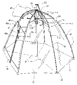
FIG S is a perspective view of the present invention.
DESCRIPTION OF THE PREFERRED EMBODIMENT
Referring to FIG 2 and FIG 3, the present invention is composed of a shaft 10,
a
protective cover 20, a handle 30 and a plurality number of supporting ribs 40.
The
functions of each component are described below:
The shaft IO consists of a upper shaft 11 and a lower shaft 12, the total
length of the
shaft 10 after assembly is slightly longer than the supporting ribs 40; an
indentation 11 a is
on the upper shaft 11, a stopper llal protruding out on the upper shaft 11 is
on the
indentation 11 a; a fixing ring 11 b, a runner 11 c and a running ring 11 d
are on the upper
shaft 11; the fixing ring 11 b is on top of the upper shaft 11, the runner 11
c is beneath the
fixing ring 11 b, the running ring I 1 d is below the runner 11 c; two ropes
11 a connecting to
the runner 11 c and running ring I 1 d respectively stretch out from the cap 1
l f on top of the
upper shaft 11 and connect to an opening ring l lcl and a closing ring l ldl
respectively:
The protective cover 20 is in polygon shape with equal sides and topped with a
4

CA 02456228 2004-O1-26
center hole 21, the protective cover 20 wraps the upper shaft 11 from top and
is fixed onto
the fixing ring 11 b by the cap 11 f; the protective cover 20 has the same
amount of tip
cover 22 corresponding to each tip of the supporting rib 40, also has a
viscous fastening
part 23 corresponding to each of the rib 41; a zipper door 24 is on one side
of the
protective cover 20, a ground mats 25 covering ground with the size of the
opened
supporting ribs 40 stretches from the bottom of the zipper door 24; the ground
mats 25
has a tri-directional zipper 26.
The handle 30 wraps around the cap 11 f and is fastened on the top of the
upper shaft
11.
The supporting ribs 40 consists of a plurality number of ribs 41 and
stretchers 42, a
connector 41 a is on the proper location of the rib 41 to make the rib 41 fold
outward; the
two ends of the rib 41 are connected to the fixing ring 11b and the tip cover
22 of the
protective cover 20 respectively; the two ends of the stretcher 42 are
connected to the
corresponding rib 41 and the brim of the runner 11 c respectively.
'15 Referring to FIG 4A, FIG 4B and FIG 4C and based on the structure
described above,
when users intend to open the present invention, they pull the opening ring 11
c 1
connecting to the runner 11 c to have the runner 11 c move up albng the upper
and lower
shaft 11, 12 first, the stretchers 42 are pulled upward along with the runner
11 c, the ribs
41 are also stretched open to prop the protective cover 20 open; the runner 11
c is fixed by
the stopper llal to maintain the present invention in open state; users can
split the upper
5

CA 02456228 2004-O1-26
and lower shaft 11, 12 and pull the tri-directional zipper 26 to have the
protective cover
20 in enclosed condition; users can come in and out through the zipper doors
24: When
users intend to recover the present invention, they can unzip the tri-
directional zipper 26
to let the protective cover 20 in loose state, connect the upper and lower
shaft 11, 12
together to form a rail for the running ring 11 d, users then pull the closing
ring 11 d l
connecting to the running ring l l d and have the running ring l l d move up
along the
upper shaft 11; the running ring 11 d pushes the stopper 11 a 1 down into the
indentation
11 a, the runner 11 c moves down by the push from the supporting ribs 40 to
have the
supporting ribs 40 close inward; users can fold the supporting ribs 40
externally from the
connector 41 a; the viscous fastening part 23 can stick the protective cover
20 and
supporting ribs 40 together; moreover for better fastening and easy
replacement of the
protective cover 20; the ground mats 25 with the tri-direction zipper 26 can
wrap the
present invention to seal completely for storage.
FIG 5 shows an application of the present invention, while fishing, users can
install
the present invention ashore or on dock and apply the protective cover 20 for
the wind
and rain resistant function; the present invention is very convenient for
users in constantly
moving. It can also be applied to a playroom for children or a resting place
owthe beach.
While a preferred embodiment of the invention has been shown and described in
detail, it will be readily understood and appreciated that numerous omissions;
changes
and additions may be made without departing from the spirit and scope of the
invention.
6

Dessin représentatif
Une figure unique qui représente un dessin illustrant l'invention.
États administratifs

2024-08-01 : Dans le cadre de la transition vers les Brevets de nouvelle génération (BNG), la base de données sur les brevets canadiens (BDBC) contient désormais un Historique d'événement plus détaillé, qui reproduit le Journal des événements de notre nouvelle solution interne.

Veuillez noter que les événements débutant par « Inactive : » se réfèrent à des événements qui ne sont plus utilisés dans notre nouvelle solution interne.

Pour une meilleure compréhension de l'état de la demande ou brevet qui figure sur cette page, la rubrique Mise en garde , et les descriptions de Brevet , Historique d'événement , Taxes périodiques et Historique des paiements devraient être consultées.

Historique d'événement

Description Date
Demande non rétablie avant l'échéance 2008-01-28
Le délai pour l'annulation est expiré 2008-01-28
Inactive : Abandon. - Aucune rép dem par.30(2) Règles 2007-07-03
Réputée abandonnée - omission de répondre à un avis sur les taxes pour le maintien en état 2007-01-26
Inactive : Dem. de l'examinateur par.30(2) Règles 2007-01-02
Inactive : CIB de MCD 2006-03-12
Demande publiée (accessible au public) 2005-07-26
Inactive : Page couverture publiée 2005-07-25
Exigences relatives à une correction du demandeur - jugée conforme 2005-07-14
Inactive : CIB en 1re position 2004-03-26
Inactive : CIB attribuée 2004-03-26
Lettre envoyée 2004-03-05
Inactive : Certificat de dépôt - RE (Anglais) 2004-03-05
Demande reçue - nationale ordinaire 2004-03-05
Toutes les exigences pour l'examen - jugée conforme 2004-01-26
Exigences pour une requête d'examen - jugée conforme 2004-01-26

Historique d'abandonnement

Date d'abandonnement Raison Date de rétablissement
2007-01-26

Taxes périodiques

Le dernier paiement a été reçu le 2006-01-23

Avis : Si le paiement en totalité n'a pas été reçu au plus tard à la date indiquée, une taxe supplémentaire peut être imposée, soit une des taxes suivantes :

  • taxe de rétablissement ;
  • taxe pour paiement en souffrance ; ou
  • taxe additionnelle pour le renversement d'une péremption réputée.

Les taxes sur les brevets sont ajustées au 1er janvier de chaque année. Les montants ci-dessus sont les montants actuels s'ils sont reçus au plus tard le 31 décembre de l'année en cours.
Veuillez vous référer à la page web des taxes sur les brevets de l'OPIC pour voir tous les montants actuels des taxes.

Historique des taxes

Type de taxes Anniversaire Échéance Date payée
Taxe pour le dépôt - petite 2004-01-26
Requête d'examen - petite 2004-01-26
TM (demande, 2e anniv.) - petite 02 2006-01-26 2006-01-23
Titulaires au dossier

Les titulaires actuels et antérieures au dossier sont affichés en ordre alphabétique.

Titulaires actuels au dossier
CHUNG-CHENG WU
Titulaires antérieures au dossier
S.O.
Les propriétaires antérieurs qui ne figurent pas dans la liste des « Propriétaires au dossier » apparaîtront dans d'autres documents au dossier.
Documents

Pour visionner les fichiers sélectionnés, entrer le code reCAPTCHA :


Pour visualiser une image, cliquer sur un lien dans la colonne description du document (Temporairement non-disponible). Pour télécharger l'image (les images), cliquer l'une ou plusieurs cases à cocher dans la première colonne et ensuite cliquer sur le bouton "Télécharger sélection en format PDF (archive Zip)" ou le bouton "Télécharger sélection (en un fichier PDF fusionné)".

Liste des documents de brevet publiés et non publiés sur la BDBC .

Si vous avez des difficultés à accéder au contenu, veuillez communiquer avec le Centre de services à la clientèle au 1-866-997-1936, ou envoyer un courriel au Centre de service à la clientèle de l'OPIC.

({010=Tous les documents, 020=Au moment du dépôt, 030=Au moment de la mise à la disponibilité du public, 040=À la délivrance, 050=Examen, 060=Correspondance reçue, 070=Divers, 080=Correspondance envoyée, 090=Paiement})


Description du
Document 
Date
(aaaa-mm-jj) 
Nombre de pages   Taille de l'image (Ko) 
Abrégé 2004-01-25 1 19
Description 2004-01-25 6 239
Revendications 2004-01-25 2 53
Dessins 2004-01-25 7 161
Dessin représentatif 2005-06-28 1 16
Accusé de réception de la requête d'examen 2004-03-04 1 176
Certificat de dépôt (anglais) 2004-03-04 1 158
Rappel de taxe de maintien due 2005-09-26 1 110
Courtoisie - Lettre d'abandon (taxe de maintien en état) 2007-03-25 1 175
Courtoisie - Lettre d'abandon (R30(2)) 2007-09-24 1 167