Note: Descriptions are shown in the official language in which they were submitted.
CA 02456398 2004-O1-29
Docket No. 62334.1
POLE REINFORCING STRUCTURES
BACKGROITND OF THE INVENTION
[0001) 1. Field of ttae Invention:
[0002] The present invention is directed to the field of reinforcing elements
to be used within the
service utilities industries to reinforce utility poles and the Like.
[0003] 2. General Background and State of the Art:
[0004) Wooden utility poles are in common use for stringing power cables,
television cables,
telephone wires and other types of cables or wires over long distances. While
these types of poles
may have a substantial life expectancy, they may eventually need to be
replaced as a result of age,
deterioration or physical damage or to comply with safety regulations. As an
alternative to a
replacement, which may cause disruption of utility services, reinforcing
elements are known which
can be lodged into the ground proximate to the utility pole, and then secured
to the utility pole in
order to reinforce the base structure of the utility pole, thereby increasing
the useful life of the utility
pole. A representative reinforcing element is illustrated, for example, in
i3.S. Design Patent No.
425,631 issued lVlay 23, 2000. The reinforcing element of the 425,631 design
patent is formed from
a bent sheet of steel which may be partially or fully wrapped around a utility
pole and driven into the
ground to lend support to the utility pole. The design according to the
425,631 patent provides
support by bracing and therefore stabilizing the utility pole.
SLT1~IMARY OF THE INVENTION
[0005) The present invention is directed to a utility pole reinforcing element
which features a
stronger, moxe structurally sound design having almost completely enclosed or
enclosed channels at
outer edges of the reinforcing element which when secured to utility poles
provides a more
structurally resilient reinforcing element for the utility pole. The present
invention is depicted in the
appended drawings and more fully described in the following detailed
description of the invention
and as set forth in the appended claims.
BRIEF 11ESCRIPTION OF THE FIGURES
[0006) Fig. 1 depicts a perspective view of a utility pole reinforcing element
of the present
invention.
[0007) Fig. 2 depicts a cross-sectional view of the reinforcing element of
Fig. 1.
[coos) Fig. '3 depicts a perspective view of a first alternative embodiment of
a reinforcing
element.
L.osAngeles/130945.2
CA 02456398 2004-O1-29
Docket No. 62334.1
[0009] Fig. 4 depicts a cross-sectional view of the first alternative
embodiment of Fig. 3.
[0010] Fig. 5 depicts a perspective view of the second alternative embodiment
of the reinforcing
element.
[0011] Fig. 6 depicts a cross-sectional view of the second alternative
embodiment of Fig. 5.
[0012] Fig. 7 depicts a perspective view of a third alternative embodiment of
the reinforcing
element.
[0013] Fig. 8 depicts a cross-sectional view of the third alternative
embodiment of Fig. 7.
[0014] Fig. 9 depicts a perspective view of a fourth alternative embodiment of
the reinforcing
element.
[OO1S] Fig. 10 depicts a cross-sectional view of the fourth alternative
embodiment of Fig. 9.
DETAILED DESCRIPTION OF THE INVENTION
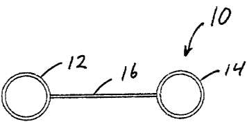
[0016] Fig. I depicts a pezspective view of a pole reinforcing element 10
according to the
present invention. The pole reinforcing element 10 includes two hollow
cylinders 12 and 14
interconnected by a web 16 that extends from the top 18 to the base (riot
shown) of the pole
reinforcing element 10. The cylinders 12 and I4 and the web I6 are preferably
formed from
structural grade steel. The steel is preferably galvanized prior to
fabrication or galvanized or painted
with an environmentally resistant coating after fabrication. The steel
components have a thickness
in a range of 3 mrn to 12 mm. The thickness of the cylinders 12 and 14 may be
greater than or Less
than the thickness of the web I6. The length of the pole reinforcing element
10 can be in a range of
2 to 5 meters in length. However, a length in the range of 2.4 to 2.7 meters
for most standard size
utility poles is adequate: The width of the web Ib section of the pole
reinforcing element 10 can be
in the range of 10 cm to 25 cm although larger widths may be appropriate for
larger size utility
poles. The diameter or width of the cylinders 12 and 14 is preferably in the
range of 6 cm to 15 cm.
[0017] Fig. 2 depicts a cross-sectional view of the pole reinforcing element I
O according to Fig.
1. As illustrated in Fig. 2, the web 16 connects to the cylinders 12 and 14 in
a manner such that if
the plane of the web was extended, it would pass through the centerline of the
cylinders 12 and 14.
It will be appreciated by those skilled in the art, however, that the line of
attachment of the web 16 to
the cylinders 12 and 14 may be offset from the centerline of the cylinders.
[0018] Fig. 3 depicts a perspective view of a first alternative embodiment of
the pole reinforcing
element I0', which also includes hollow cylinders I2 and 14. The web 16' of
Fig. 2, however,
generally connects tangentially to the cylinders I2 and 14. This construction
is more clearly shown
_2_
LosAngeles/130945.2
CA 02456398 2004-O1-29
~~ Docket No. 62334.1
by the cross-sectional view of Fig. 4, For the farst alternative embodiment of
Figs. 3 and 4, the
materials, thiclcnesses, lengths and widths described above with respect to
Fig. 1 are also applicable.
[0019] Fig. 5 depicts a perspective view of a second alternative embpdiment of
a pole -
reinforcing element 20. In this embodiment, the web 22 interconnects
oppositely disposed channels
24 and 26. The channels 24 and 26 are generally constructed in a hollow
rectangular shape,
although a square configuration would be applicable. The web 22 is illustrated
in the cross-sectional
view of Fig. 6 as connecting the channels 24 and 26 generally in the center of
the long axis of the
channels 24 and 26. However, the web 22 could also be offset from the
centerline or even connected
to the ends of the channels 24 and 26. With respect to the construction of the
pole reinforcing
structure 20 depicted in Figs. 5 and 6, tile types of materials, thicknesses,
lengths and widths
described above with respect to the first embodiment would also apply to this
design.
(OOZO] From the three foregoing embodiments of the present invention, it may
be appreciated
that other types of geometric channel shapes could be attached to the lateral
sides of the web. For
example, triangular, oval or other types of polygonal columns or channels
could be utilized. For
ease of fabrication, however, the rectangular or cylindrical channels are
preferred.
[0021] Fig. 7 depicts a perspective view of a third alternative embodiment of
a pole reinforcing
element 30. The configuration of Fig. 7, which is also depicted in the cross-
sectional view of Fig. 8,
depicts generally triangular shaped elements 32 and 34 connected to the
lateral external ends of an
angled web 36. The triangular shaped elements 32 and 34 may or may not be
closed, although
preferably they are close to being closed or completely bounded. The web
element 36 may be
straight or, as depicted in the figures, may have a bend in the center section
to form a flattened "V"
shape. For the configuration according to Figs. 7 and 8, the materials,
thicknesses, lengths and
widths discussed above with respect to Figs. I and 2 are also equally
applicable to this design.
[0022] Fig. 9 depicts a perspective view of another alternative embodiment of
the invention
which is also shown in the cross-sectional view of Fig. 10. In this
embodiment, a pole reinforcing
element 40 includes a web 46 that connects to two hollow channels 42 and 44 as
described in the
foregoing embodiments of the invention. The web 46, however, only extends
partially from the top
48 of the channels 42 and 44 to a mid point 50 above the base 52 of the
channels 42 and 44. This
configuration will allow the channels 42 and 44 to more readily be driven into
the ground next to the
utility pole, and only a portion, or no portion, of the web 46 may be driven
into the ground.
10023] In use, the various embodiments of the present invention may be placed
against a utility
pole or in proximity to a utility pole, either individually or in pairs. They
may be placed such that
the pole is positioned adjacent to the web of the pole reinforcing elements.
The pole reinforcing
_ -3-
LasAngetes/130945.2
CA 02456398 2004-O1-29
Docket No. 62334,1
elements are then driven into the ground. A hammer, pile driver or similar
device may be used to
place the pole reinforcing element. Alternatively, a device to vibrate the
pale reinforcing element
into the ground may be used' as is known in the art. After the pole
reinforcing element is fixed in the
ground, metal strapping elements and/or bolts may be used to secure the pole
reinforcing element to
the utility pole.
[0024j Generally, the pole reinforcing element is driven into the ground to
approximately one-
half of its length. However, the ground or soil conditions, the integrity of
the base of the utility pole
and other environmental factors may be considered in determining the length of
the pole reinforcing
element and the division between the length driven into the gxound as opposed
to the length
extending above the ground available to secure the utility pole. Moreover, for
the embodiment with
the web only partially extending from the top to some mid point before
reaching the base of the
geometric channels, a greater percentage of the length of the pole reinforcing
element including the
web may remain protruding from the ground.
[0025] It may be appreciated by those skilled in the art that the utility pole
can be secured at
multiple locations on the lower portion of the utility pole, and that
preferably the utility pole is
secured both proximate to the ground and proximate to the top of the pole
reinforcing element in
addition to being secured at intermediate locations on the free standing
portions of the utility pole
and pole reinforcing element. As an alternative, the utility pole and the pole
reinforcing element can
be continuously wrapped from the bottom portion extending from the ground all
the way to the top
of the pole reinforcing element to maximize the securement of the pole
reinforcing element to the
utility pole.
[0026] I-laving described the preferred and alternative embodiments of the
present invention, it is
recognized that those skilled in the art will be able to make modifications of
the design, which
remain contemplated by the present invention in the scope of the claims
appended hereto.
Accordingly, the invention is to be understood as being represented by the
foregoing specification
but limited only by the appropriate scope of the appended claims.
LosAngeles/130945.2