Note: Descriptions are shown in the official language in which they were submitted.
CA 02456766 2004-02-09
WO 03/018264 PCT/CA02/01323
-1-
WHEEL PULLING APPARATUS
Field of the Invention
The present invention relates to the field of vehicle repair and maintenance,
and in
particular, relates to a device for the removal of wheels, brake drums, brake
rotors, and
the lilce, from a vehicle.
Baclc~round of the Invention
During the repair or maintenance of a vehicle, including truclcs, automobiles
and
the like, it is frequently necessary to remove the wheels, brake rotors and/or
brake drums.
However, the tolerances between these devices is very small. For example, the
clearance
between the inner wheel rim and the wheel hub are typically on the order of
only several
thousands of an inch. Similarly, the clearance between a brake drum or brake
rotor and
the wheel hub is also very small. Because of these small tolerances and
because the wheel
hub assembly bears the weight of the vehicle, extended use of the vehicle can
frequently
cause the inner wheel rim, the brake drum, or the brake rotor, to become
essentially fused
or seized on the wheel hub.
Once a wheel, for example, is seized on the wheel hub, it can be very
difficult to
remove the wheel from the vehicle by hand. The common practice in the vehicle
repair
industry is to have a mechanic hoist the vehicle and hammer on the seized
wheel, from
the inside, until the wheel becomes loose enough to remove.
This method can, however, cause damage to the rim, the brake drum, the bralce
rotor, or other parts of the vehicle during hammering. Further, this operation
can take an
CA 02456766 2004-02-09
WO 03/018264 PCT/CA02/01323
-2-
unacceptable amount of time to release the seized part. Yet further, the
safety of the
mechanic can be jeopardized when hammering a wheel part while under the
vehicle.
Still further, if the vehicle should need repair while traveling, such as fox
example,
caused by having a flat tire, it can often be excessively difficult to remove
the seized part
by hand. Further, hammering of the part with a heavy object is not generally
an acceptable
option because of the limited space under the vehicle created by lifting the
vehicle with a
small manual vehicle jack.
In order to address these problems, the prior art provides for a number of
different
devices to assist in this type of vehicle repair, and to assist in removal of
a wheel, a bralce
rotor, a brake drum, or the like, from a vehicle. These devices may generally
be described
as "wheel-pulling" apparatuses, even though they can also be used for removal
of brake
drums or brake rotors, in addition to the removal of wheels or wheel rims,
from the
vehicle.
Some of these known prior art devices are described hereinbelow.
Prior Art
In US Patent No. 3,402,455 (Converse), issued April 17, 1967, a wheel pulley
device is described having a central threaded screw which pushes on the hub
(or axle) of
the vehicle wheel, while two spring-loaded hooks grasp and pull at the rear of
the wheel
or brake drum to be removed.
In US Patent No. 3,689,978 (Kelso), issued September 12, 1972, a similar wheel
or gear pulley device is shown having a central threaded screw which pushes on
the hub of
the vehicle wheel or gear. Two hooks are attached in the radial grooves of a
central yoke
or bridge so that the hooks can be moved to be essentially parallel to the
central threaded
screw during use.
US Patent No. 4,771,528 (Stromberg), issued September 20, 1988, describes a
spindle pulley for removal of the front wheel spindle on a four-wheel drive
vehicle. Again,
the described spindle pulley has a central threaded screw which pushes on the
axle, while
a base plate acts to pull on the spindle. It should be noted that the user is
warned not to
hammer on the threaded screw, since internal axle parts may be damaged.
CA 02456766 2004-02-09
WO 03/018264 PCT/CA02/01323
-3-
US Patent No. 4,90,925 (Johnson), issued March 20, 1990, describes a wheel hub
puller which is used to remove the wheel hub from a axle housing. Again, a
central
threaded screw acts to push on the axle, while a support frame, bolted to the
wheel hub
using the wheel lugs (and bolts) acts to pull on the wheel hub.
US Patent No. 6,012,211 (Ochoa et al.), issued January 11, 2000, describes a
wheel puller apparatus having a plate which rests upon the wheel mounting
studs, and
having two threaded hook portions which extend through the plate and hook onto
the rear
of the wheel. As bolts are tightened on the threaded hooks, the plate pushes
against the
wheel mounting studs, while the hoolcs pull on the wheel rim. The two hooks
are
alternatively "pulled" so that the pushing and pulling forces are first
applied on one side
of the wheel and then applied on the opposite side of the wheel. This results
in a roclcing
motion which can result in damage to the wheel or brake assembly due to the
side-to-side
motion of the wheel as it is being freed.
US Patent No. 6,237,206 (Bezemer et al.), issued May 29, 2001, describes a
device for removal of a wheel from a wheel hub, having a threaded screw
connected to a
retainer through a base plate, which threaded screw is engaged with the wheel
hub, and a
series of chains with hooks for releasably attaching the base plate to the
wheel. As the
treaded screw is tightened, the retainer pushes on the retainer, while the
chains act to pull
on the wheel rim.
While these devices have shown some utility in the field, they are primarily
intended for use on trucks and heavy duty equipment in a garage environment,
or they are
intended for use with wheels that are hub-mounted, as opposed to being stud-
mounted, on
the vehicle.
Accordingly, while these prior art devices have proven to be of some use, the
continued mechanic's practice of hammering seized parts is evidence that a
further
improvement in wheel-pulling apparatuses would be beneficial.
CA 02456766 2004-02-09
WO 03/018264 PCT/CA02/01323
-4-
Summary of the Invention
Accordingly, it is a principal object of the present invention to provide a
simple
wheel-pulling device which can be readily used on a wide variety of vehicle
types for
removal of wheels, brake rotors and/or brake drums.
It is a further object of the present invention to provide a wheel-pulling
device
which acts to avoid exerting a pushing force directly on the axle or hub of
the vehicle.
It is still a further object of the present invention to provide a wheel-
pulling device
which acts while avoiding a damaging rocking, or side-to-side- motion.
These and other objects are attained by providing a wheel-pulling device
having a
push plate which acts to push upon the mounting studs of a wheel, hook members
to pull
on the wheel, brake rotor or brake drum, a pull plate to which the hook
members are
attached, and a threaded pilot shaft which is threaded through the pull plate
so that when
tightened, the pilot shaft acts to push against the push plate (which in turn
acts to push
against the wheel studs), and pulls the hoolc members so as to pull the wheel
rim.
Accordingly, the present invention provides a wheel-pulling apparatus
comprising:
a. a push plate adapted to be placed in operative contact with a plurality of
wheel studs;
b. a pull plate having two or more hook attachment points;
c. two or more hook members adapted to be attached, at a first end, to said
pull plate at said hook attaclunent points,.and which hook members are
adapted to connect, at a hook end, to a wheel rim, a brake drum or a brake
rotor; and
d. a threaded pilot shaft which threads through a threaded opening in said
pull
plate, and abuts, at a proximate end, against said push plate, and which
pilot shaft has, at a distal end, a turning mechanism for turning said
threaded pilot shaft within the threaded opening in said pull plate, so that
said push plate exerts a pushing force on said wheel studs, and said pull
plate exerts a pulling force on said wheel rim, brake drum or brake rotor,
through said hoolc members.
CA 02456766 2004-02-09
WO 03/018264 PCT/CA02/01323
-5-
Preferably, the wheel-pulling apparatus also provides a plurality of soclcet
pins
adapted to being attached to said plurality of wheel studs, wherein said
socket pins are in
contact with said push plate.
In a second aspect, the present invention also provides a method for the
removal
of a brake drum a wheel, or a brake rotor using an apparatus of the present
invention as
herein described.
Detailed Description of the Invention
In the context of the present specification, the phrase "wheel studs" is
intended to
mean the bolt ends which typically extend from the wheel hub on which the
wheel, brake
rotor, brake drum, or the like, are mounted. The "wheel studs" normally remain
on the
vehicle after the wheel has been removed. However, the phrase is also meant to
include a
series of bolts which might be inserted into the wheel stud openings on the
hub in the
situation where the actual studs are removed when the wheel is removed. The
number of
wheel studs can vary from vehicle to vehicle, but typically, the number of
wheel studs
ranges from between 3 and 8, but more typically is between 4 and 6.
In the practice of the present invention, it is preferred that the push plate
exert a
simultaneous pushing force against a plurality of wheel studs, and more
preferably a
simultaneous pushing force against all of the wheel studs (or socket pins,
where used).
The phrase "simultaneous pushing force" is intended to mean that the push
plate generally
acts on more than one wheel stud, and preferably on all wheel studs (or socket
pins), as
the turning mechanism is turned.
Preferably, the push plate has a central recess on one surface for receiving
one end
of the pilot shaft. Where the pilot shaft has a small diameter section at the
end, the recess
in the push plate may also be a hole through the push plate, provided that the
diameter of
the hole is less than the larger diameter section of the pilot shaft.
The push plate also preferably comprises a number of holes or recesses on a
second surface into which the wheel studs of the socket pins can be inserted.
Again,
where the socket pins have a small diameter section at the end, the recess in
the push plate
may be a suitably sized hole. The number of holes or recesses, and sizes of
the holes or
CA 02456766 2004-02-09
WO 03/018264 PCT/CA02/01323
-6-
recess will preferably match, or be selected based on the number and size of
the wheel
studs or the socket pins.
The recess in second surface of the push plate might also be a circular groove
in
which all of the wheel studs or soclcet pins will fit.
The push plate is preferably circular in shape to agree with the shape of the
wheel
rim, bralce drum or brake rotor, although a variety of shapes might be used.
Preferably the
push plate is of a size to cover all of the wheel studs, but should not be
significantly larger
to avoid interference with the hook members unless allowances are made for the
hook
members to avoid interference with the push plate.
The term "hook members", or "hooks" is used in a general sense to include
devices which have a traditional hook-shaped design. However, the term can
also cover a
series of designs, including, for example, an L-shaped design which can be
used for
situations where the clearance distance between parts is relatively small.
Further, the term
hook may also be interpreted as a device which merely contains a small
"shoulder" area
which can be used to exert a pulling force on the wheel, the wheel drum or
bralce rotor.
The hoolcs are preferably attached to the pull plate at a hoolc attachment
point
using one or more bolts at a threaded end of the hook. Preferably, between 3
and 8 hook
members are used in the practice of the present invention, and more
preferably, between 4
and 6 hook members are used.
A pull plate may comprise a number of hook attachment points regardless of the
number of hooks being used. The number, size and location of the hook
attachment points
will vary depending on the size of the hooks and the configuration of the
wheel rim, brake
drum or brake rotor. The hook attachment points might be threaded holes into
which the
threaded end of the hook could be tightened, or could simply be holes through
which the
threaded end of the hook could be passed and then held in place by an
additional bolt.
The pull plate can have a wide variety of shapes and sizes. For example, the
pull
plate might be circular in shape and be provided with a series of threaded
holes into which
the hook members might be threaded. However, in a preferred configuration, the
pull
plate comprises a small central portion having a threaded central hole for the
pilot shaft to
pass through, and a plurality of radial arms extending from the central
portion, to which
CA 02456766 2004-02-09
WO 03/018264 PCT/CA02/01323
the hook members can be attached. The number of radial arms should preferably
agree
with the number of hooks to be used. Preferably the munber of radial arms
would be
between 3 and 8 and more preferably, between 4 and 6.
In a preferred embodiment, the pull plate will have a small central portion
and a
plurality of radial arms each having a slot into which the threaded end of the
hook
member can be inserted and adjusted before being tightened into place.
The pilot shaft is of sufficient length to pass through the pull plate and
abut
against the push plate. The pilot shaft is threaded in the area of where it
passes through
the pull plate, and thus is threaded into the threaded hole in the centre of
the cental
portion of the pull plate.
At one end, the pilot shaft preferably has a bolt shaped head onto which a
wrench
or a wrench-shaped crank can be attached, and thus provides a turning
mechanism for
turning the pilot shaft. Alternatively, the crank can be formed as part of the
pilot shaft so
that no additional cranlc or wrench, or the like, is required.
All parts of the apparatus of the present invention are preferably made of
materials
which are able to withstand the forces exerted during operation. A suitable
material would
be, for example, steel, for most applications.
Brief Description of the Drawings
Various embodiments of the wheel pulling apparatus of the present invention
will
now be described by reference to the following drawings wherein:
Fig. 1 is a perspective, exploded view of a wheel pulling apparatus according
to
the present invention;
Fig. 2 is a side, cut-away view of a wheel pulling apparatus according to the
present invention being used to remove a brake drum;
Fig. 3 is a perspective view of an alternative design of a wheel pulling
apparatus
according to the present invention;
Fig. 4 is a top plan view of the pull plate of the wheel pulling apparatus of
Fig. 3;
Fig. ~ is a side plan view of the pull plate of the wheel pulling apparatus of
Fig. 3;
Fig. 6 is a side plan view of a hook of the wheel pulling apparatus of Fig. 3;
CA 02456766 2004-02-09
WO 03/018264 PCT/CA02/01323
_g_
Fig. 7 is a side plan view of an alternative hook design;
Fig. 8 is a side plane view of a fiu ther alternative hook design;
Fig. 9 is a top plan view of the push plate of the wheel pulling apparatus of
Fig. 1;
and
Fig. 10 is a cut-away side view of the socket pin of the wheel pulling
apparatus of
Fig. 1
Detailed Description of the Preferred Embodiments
Other features of the present invention, as well as other objects and
advantages
attendant thereto, are set forth in the following description and the
accompanying
drawings in which like reference numerals depict like elements.
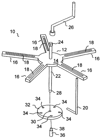
In Fig. 1, a wheel pulling apparatus 10 in accordance with the present
invention is
shown having a pull plate 12, which in this embodiment has a central portion
14 and five
radial arms 16. Each radial arm has a slot 18 through which, preferably 5
hooks 20 can be
fed. Slots 18 allow hooks 20 to be positioned in a suitable position as
described
hereinbelow.
Extending through the centre of cental portion 14 of pull plate 12 is a pilot
shaft
22 which is threaded in at least the area in contact with pull plate 12. Pull
plate 12 is also
treaded in this area to receive the threaded section of pilot shaft 22. At one
end, pilot shaft
22 has a bolt shaped end 24 which can be releasably attached to a wrench or to
a crank 26.
Crank 26 can then be used to turn pilot shaft 22.
At the other end of pilot shaft 22 is a tapered, or smaller diameter end 28
which is
adapted to fit into a recess 30 in push plate 32. Push plate 32 also contains,
in this
embodiment, 5 holes 34 into which the tapered, or smaller diameter ends 38 of
socket
pins 36 can be fitted.
Figure 2 shows the use of the device of Figure 1 to remove a brake drum 50
from
a wheel hub 42. In use, the operator would insert socket pins 36 over the
wheel studs 40
which extend from wheel hub 42. Soclcet pins 36 can be threaded onto wheel
studs 40, but
might also have a sufficiently large opening to allow socket pins 36 to be
merely inserted
over wheel studs 40. Use of the socket pins 36 can be eliminated, but is
generally
CA 02456766 2004-02-09
WO 03/018264 PCT/CA02/01323
-9-
preferred in order to minimize any damage to wheel studs 40.
For the purposes of the present document, the wheel hub 42 is generally
defined as
the area of the vehicle wheel in the general area of the vehicle axle. In the
practice of the
present invention, the force exerted on the wheel axle and/or hub is reduced
since the
push plate exerts a simultaneous force on the wheel studs. As such, the force
exerted on
the wheel hub is minimized, or at least evenly spread over the entire wheel
hub.
Once socket pins 36 are in place, push plate 32 is attached so that the
tapered ends
of socket pins 36 extend through push plate holes 34. Preferably the fit of
pins 36 in push
plate 32 is sufficiently tight to hold pins 36 and push plate 34 together with
the larger
section of pins 36 being in contact with push plate 32. Holes 34 do not need
to extend
through push plate 32, but might merely be recesses in push plate 32.
One end of pilot shaft 22 is inserted into the recess 30 in push plate 32. The
"hoolced" end of hooks 20 are then brought into contact with the back edge 52
of brake
drum 50. Details of the bralcing system are outside of the scope of this
invention, and are
not shown in the figures. The other ends of hooks 20 are fed through slots 18
in radial
arms 16 of pull plate 12. The hooks can then be bolted into place using bolts
54 and 56.
The hooks are preferably placed on radial arms 16 so that the shaft area 21 of
hooks 20 is
essentially perpendicular to the front surface 51 of brake drum 50 (or said
bralce rotor or
wheel rim, as applicable).
Once all of the hooks 20 are in place, the end of crank 26 is fitted over the
bolt-
shaped end 24 of pilot shaft 22. The crank 26 is then turned.
As the crank 26 is turned, pilot shaft 22 attempts to move through pull plate
12.
As a result of this motion, a pushing force is exerted onto push plate 32,
which in turn,
acts to exert a pushing force onto wheel studs 40 through socket pins 36. At
the same
time, a pulling force is exerted onto pull plate 12 which acts to exert a
pulling force onto
brake drum 50 through hooks 20 which are attached to the radial arms 16 of
pull plate 12.
The combination of pushing force on the wheel studs, and the pulling force on
the
bralce drum, act to free the seized brake drum from the wheel' hub. It should
be noted, that
generally only a very small movement of brake drum 50 is required using the
device of
the present invention, since once the brake drum has been freed from the wheel
hub, it can
CA 02456766 2004-02-09
WO 03/018264 PCT/CA02/01323
-10-
then be removed by hand.
In Fig. 3, a alternative design 1 OA for a wheel pulling apparatus of the
present
invention is shown having many of the same parts as in the wheel pulling
apparatus of
Figure 1. However, in this embodiment, only 4 radial arms 16A are used, and
arms 16A
are bent so as to reduce the length of hooks 20A.
Also, in this design, the holes (not shown) in push plate 32A are merely
recesses
in push plate 32A and do not extend through push plate 32A. It should also be
noted,
however, that socket pins 36 may be permanently attached to push plate 32A if
the device
is commonly used for one standard wheel stud configuration.
Also, in this embodiment, it should be noted that the slots 18 in radial arms
16A
have been eliminated in favour of pre-set holes 18A in radial arm 16A. Again,
this might
be preferred in situations where a standard wheel configuration is commonly
used.
A top plane view of the pull plate 12A of the device of Figure 3 is shown in
Figure
4. It can be seen that the central portion of 14A of pull plate 12A is
generally quite small
and merely includes a small plate around a threaded, central hole 11 through
which pilot
shaft 22 is inserted.
It should be noted, however, that numerous designs can be used in the
production
of pull plate 12, including a solid circular plate which contains holes for
hooks 20 in
appropriate locations, slots for hooks 20, or the lilce. The lcey requirements
for the pull
plate, however, are that the pull plate have holes, preferably at or near the
centre of the
plate, through which the pilot shaft can be threaded, and hook attachment
points where a
plurality of hooks can be permanently or releasably attached.
In Fig. 5, a side plane view of the pull plate of Figure 4 is shown, which
provides
more detail on the construction of the wheel pulling apparatus.
In Fig. 6, a side plane view of a hook 20 of use in the present invention is
shown.
Hoolc 20 has a shaft section 21, and preferably a threaded section 23 at one
end of the
shaft section 21 in order that the hoolc 20 can be bolted to radial arms 16.
The "hook"
section 25, may merely be a circular metal piece bent to 90 degrees from shaft
section 21.
In Fig. 7, an alternative design for hook 20 is shown, and is designated as
20A.
For removal of some types of bralce rotors, the hook shown in Figure 5 would
be
CA 02456766 2004-02-09
WO 03/018264 PCT/CA02/01323
-11-
acceptable. In some brake disk designs, both the front and back surfaces of
the rotor are
smooth for the brake pad to act against. Further, in order to aid in cooling
of the rotor,
some are built with open axeas extending from the outer perimeter of the rotor
into the
rotor, between the rotor front and back surfaces. The hoolc 20A of Figure 7
has a shaft
section 21 and treaded section 23 identical to the hook of Figure 5. However,
the hook
section 25A, is flattened along its surface to facilitate insertion of the
"hoolc" into the
brake rotor.
Hooks 20A of this design may be used in this application, as well as a variety
of
other applications.
In Fig. 8, a further side plan view of an additional hoolc design, designated
as 20B,
is shown. In this design, hook section 25B is merely the "shoulder" of shaft
section 21.
This hoolc design would be of use in removal of a brake drum, having a
relatively thin
casing.
In Fig. 9, a top plan view of the push plate 32 of Figure 1 is shown. Push
plate 32
has 5 holes 34 equally spaced around the push plate. Each hole 34 is located
at an equal
distance from the centre of the push plate 32, as indicated by line 35, and
are placed so as
to correspond to the spacing of the vehicle wheel studs. Holes 34 axe adapted
to receive
the socket pins 36, as hereinabove described. Recess 30 in the top surface of
push plate 32
is preferably centred in the middle of push plate 32, and is adapted to
receive the end of
pilot shaft 22.
Fig. 10 shows a cut-away view of a soclcet pin 36 of use in the practice of
the
present invention. Socket pins 36, in the embodiment shown in Figure 1,
comprise 2 main
sections, namely, a tapered, smaller diameter section 60, for insertion into
push plate 32,
and a larger diameter section 62 for fitting over the end of the wheel studs.
Socket pin 36
in this embodiment is threaded on the internal section 64 of larger diameter
section 62 so
that the soclcet pin 36 can by threaded onto the wheel stud.
Thus, it is apparent that there has been provided, in accordance with the
present
invention, a wheel pulling apparatus which fully satisfies the means, objects,
and
advantages set forth hereinbefore. Therefore, having described specific
embodiments of
CA 02456766 2004-02-09
WO 03/018264 PCT/CA02/01323
-12-
the present invention, it will be understood that alternatives, modifications
and variations
thereof may be suggested to those skilled in the art, and that it is intended
that the present
specification embrace all such alternatives, modifications and variations as
fall within the
scope of the appended claims.
Additionally, for clarity and unless otherwise stated, the word "comprise" and
variations of the word such as "comprising" and "comprises", when used in the
description and claims of the present specification, is not intended to
exclude other
additives, components, integers or steps.