Note: Descriptions are shown in the official language in which they were submitted.
CA 02456884 2004-02-04
MULTI-POINT DOOR LOCK AND OFFSET EXTENSION BOLT ASSEMBLY
FIELD OF THE INVENTION
The present invention relates to a door lock and bolt assembly. More
specifically, the
present invention relates to a mufti-point door lock extension bolt assembly
with an adaptor
enabling at least an extent of the extension bolt to be offset relative the
lock mechanism and to
be concealed within the door.
BACKGROUND OF THE INVENTION
Mufti-point door lock systems used in connection with door assemblies are
generally
known in the art. Conventional mufti-point lock systems are generally used in
sliding door,
swinging door and/or french door assemblies. Typical mufti-point door lock
systems include
latch or bolt assemblies that extend from the lock unit to engage the door
frame, thus enabling
the door to be securely locked to the frame. Plural latches or bolts are used
to provide added
security by locking the door to the frame at a plurality of locations. For
example, typical multi-
point locking door assemblies include a central lock mechanism that controls a
central latch, as
well as at least one bolt mechanism that engages the door frame above or below
the door. The
bolt mechanism of such mufti-point door locks has an elongated body that
extends from the
central lock mechanism to the door frame, typically in the form of an
elongated extension bolt.
For added security, most of such mufti-point locking doors have extension
bolts extending from
the central lock to both the top frame, and the floor threshold or bottom
frame member. The
2o extension bolts of such devices are positioned along an edge of the door,
or are located in a
channel or other passageway within the door.
Example of these types of prior art assemblies are shown in FIGS. l and 2.
FIG. 1
shows a door with a mufti-point locking system that has an extension bolt
extending from the
central lock unit and exposed along an edge of the door member of the
assembly. The edge
faces outwardly towards the frame. This type of mufti-point locking assembly,
thereby has
extension bolts passing along the outer edge of the door, usually along the
edge that first
separates from the door jamb during opening of the door. In the embodiment,
the door edge
may be slightly recessed to accommodate flush installation of the extension
bolts. FIG. 2
depicts an example of an alternative structure of a typical mufti-point lock
assembly. FIG. 2
CA 02456884 2004-02-04
2
shows a mufti-point lock assembly in which the extension bolts extend through
an internal
channel of the door, to engage the door frame at the top and/or bottom of the
door. This type of
door lock assembly, with an extension bolt passing through the body of the
door, provides a
locking bolt structure that is spaced inward of the door edge and is thereby
concealed within the
door. Depending on the specific application, this arrangement may provide
added security by
preventing tampering; and it provides a cleaner appearance with less exposed
mechanical parts.
Each of these types of mufti-point lock assemblies offer benefits that may
make one
preferred for use in a given situation. For example, there may be applications
in which added
security would be achieved by providing extension bolts that pass through the
body of the door,
1o rather than being exposed along an edge. Alternatively, it may be
preferable to have the
extension bolts located along the edge of the door, such as may be desired for
ease of
installation or replacement of an existing type of assembly and to mate with
existing recesses in
the door frame. It is understood that the central lock units of the lock
assemblies of FIGS. 1 and
2 have different structural configurations to accommodate the different
structural configurations
of the extension bolts. Each central lock unit is specific for its particular
extension bolt
configuration. Because of such needs, it would be beneficial to have available
a lock assembly
that may be adapted for use, capable of modification to accommodate either
structure of an
extension bolt.
Therefore, it is desirable to provide a mufti-point locking assembly capable
of such
2o adaptation by a user, and that is suitable for alternate positioning the
passage of extension bolts,
or similar extension bolt members, relative the central locking mechanism.
Further, it is
desirable to provide an adaptable extension bolt assembly that is capable of
being mounted to a
central lock device configured for an extension bolt such as is shown in FIG.
l, and yet with an
altered alignment to permit passage of the bolts inside the door such as is
shown in FIG. 2. The
present invention is provided to solve these as well as other needs.
SUMMARY OF THE INVENTION
The present invention provides a locking door assembly having a door member
mounted
to a door frame and moveable between at least an open and closed position,
with a lock
3o assembly having a central lock member positioned in the door member. The
lock assembly has
at least one actuator member connected to the central lock that is moveable
along an axis of
extension between a first position and second position. The assembly further
has an extension
CA 02456884 2004-02-04
3
bolt with an elongated body extending along a bolt axis, and a proximal end
connected to the
actuator member and a distal end with a projection configured to mate with a
receiver for
locking the door in position. The connection of the actuator and the extension
bolt includes an
adaptor body with an intermediate length extending transverse to the extension
bolt axis. This
s arrangement defines an extent of separation of the extension bolt axis from
the actuator axis.
The present invention also provides a mufti-point lock assembly as described
above, that
is configured to be mounted in a door to provide a central lock assembly with
an actuator
moveable along an axis of movement, and an extension bolt with an elongated
body axis. The
actuator is secured to the extension bolt by an adaptor having a length that
extends transverse
1 o the elongated bolt axis, thus placing the extension bolt axis a distance
away from the actuator
axis. The present invention further provides a lock assembly in which the
connection of the
extension bolt to the actuator is configured for alternate connection by a
user. In a first
configuration, the bolt and actuator are connected in linear relationship such
that the axis of the
extension bolt is in substantial alignment with the actuator axis. In a second
configuration, the
1s the adaptor length is transverse to the bolt axis to separate the actuator
axis a distance from the
bolt axis.
The present invention further provides an adaptor for connecting an extension
bolt to a
central lock device of a mufti-point lock assembly for a door. The adaptor has
an adaptor body
with a first end connected to a mating portion of the lock actuator member,
and a second end
2o connected to the elongated extension bolt. The adaptor has a body length,
extending between
the first end and the second end, which extends transverse to the elongated
extension bolt. In
this manner, the adaptor may be connected to the structure of a mufti-point
lock assembly to
displace the extension bolt into alignment with an internal passageway through
the associated
door, spaced away from the edge of the door.
25 Other advantages and aspects of the present invention will become apparent
upon reading the following description of the drawings and detailed
description of the invention
BRIEF DESCRIPTION OF THE DRAWINGS
In accompanying drawings, in which like numerals are employed to designate
like parts
30 throughout the same,
FIG. 1 is a partial elevational view of a prior art door and mufti-point lock
assembly
having an extension bolt assembly positioned along the edge of the door;
CA 02456884 2004-02-04
4
FIG. 2 is a partial elevational view of a prior art door and mufti-point lock
assembly
having a concealed extension bolt assembly extending in a channel within the
body of the door;
FIG. 3 is an elevational view of a door assembly and mufti-point lock assembly
in
accordance with the present invention;
FIG. 4 is a partial perspective view of the mufti-point door lock assembly of
FIG. 3;
FIG. 5 is a partial elevational view of the mufti-point door lock assembly of
FIG. 3;
FIG. 6 is a partial sectional view of the assembly if FIG. 5, with the
interior of the
central lock assembly in view and connections of bolt components shown in
broken lines;
FIG. 7 is a perspective view of the adaptor of the present invention;
t o FIG. 8 is a side view of the adaptor of the present invention; and
FIG. 9 is a top view of the adaptor of the present invention.
DETAILED DESCRIPTION OF THE DRAWINGS
While this invention is susceptible of ernbodirnents of many different forms,
there is
shown in the drawings and will herein be described in detail preferred
embodiments of the
invention, with the understanding that the present disclosure is considered to
be an
exemplification of the principles of the invention and is not intended to
limit the broad aspect of
the invention to the embodiments illustrated.
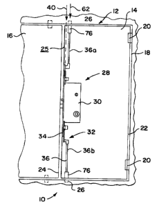
Refernng now to FIG. 3, there is shown a mufti-point door locking assembly 10
of the
2o present invention. The door lock assembly 10 is shown operatively connected
to a conventional
swinging door assembly 12. The door assembly 12 comprises a primary door
member 14 or
movable member, mounted within a master door frame 18. The primary door 14 is
mounted by
conventional means to provide reciprocal sliding and/or swinging movement
within the door
frame 18, thereby enabling ingress and egress through the door assembly 12.
Such conventional
mountings include hinge connections 20 along a jamb edge 22 of the door 14, or
cooperative
sliding track arrangement (not shown) between the frame 18 and the door member
14. In the
embodiment shown, secondary door member 16 is also mounted to the door frame
18, and is
located adjacent the lock edge 24 of the door, opposite the door jamb edge 22.
The secondary
door 16 also may be a movable door member capable of sliding and/or swinging
within the door
3o frame I 8, and having a locking assembly 10 as is depicted in the primary
door member 14, or
some other locking structure. Alternatively, the door member is mounted
without the use of a
secondary door member 16, such that a portion of the door frame is located
adjacent the lock
CA 02456884 2004-02-04
S
edge 24 of the door 14. The mufti-point door locking system 10 of this
invention is operatively
connected to the door assembly 12, for enabling the door member 14 to be
securely locked to
the door frame 18. In the present embodiment, the locking system 10 is
connected to the
primary door member 14. It is also contemplated that the locking system 10 may
be connected
to the second door member 16, if desired, without departing from the scope of
the present
invention. Therefore, use of the term door frame may be used in reference to
any adjacent
structure suitable for securement of the door, including a door frame jamb 18
or an adjacent
door structure 16.
The door frame 18 preferably has one or more lock bolt receivers 26 integral
with the
1o door frame 12 for receiving a bolt projection of the assembly for locking
the door in a selected
position. In the embodiment shovsm in FIG. 3, there is a top and bottom
receiver 26, each for
receiving a respective bolt projection of the lock assembly 28. The lock
assembly 28 includes a
central lock body 30 with at least one extension bolt assembly 32. The
extension bolt assembly
32 preferably includes an actuator member or actuator arm 34 and a connected
extension bolt
member 36.
The body 30 of the central lock assembly 28 has an internal mechanism 38
configured
for manipulation by a user to lock and unlock the door member 14 relative the
door frame 18.
Manipulation of the central lock assembly, and resulting interface movement of
the internal
mechanism 38, causes movement of the actuator arm 34 extending from the
central lock body
30. Such manipulation causes movement of the actuator 34 between a first
position located
close to the central lock body 30, and a second position that is extended a
distance further from
the central lock body 30. In the preferred embodiment, the actuator arm 34
moves between the
first and second position along an axis of movement 40 (FIG. 5).
As shown in FIGS. 4-6, the central lock body 30 includes a housing 42
providing a
compartment for the internal mechanism 38, and the actuator arm 34 preferably
extends from
the housing 42 at the lock edge 24 of the door 14. In the preferred form of
the invention, the
mufti-point lock arrangement includes a latch member 44 extending from the
face plate 46 that
extends along the lock edge 24 of the door 14. The face plate 46 is preferably
formed of flat
sheet stock material such as metal, mounted directly to the outer surface 25
of the door edge 24,
3o and is thereby exposed along the lock edge 24 of the door 14.
The lock assembly preferably includes a deadbolt member 48 that may be
deployed to an
extended position protruding from the face plate 46 to engage an associated
portion of the door
CA 02456884 2004-02-04
6
frame 18, thereby providing one of the points of the multi-point locking
arrangement. The lock
assembly internal mechanism 38 is configured to be manipulated by a user to
control locking
engagement between the door member 14 and the door frame 18, by controlling
movement of
the latch member 44, the dead bolt member 48, and each extension bolt assembly
32. As shown
in FIG. 6, the mechanism 38 of the central lock assembly 28 preferably
includes at least one
slide member 50 and an associated drive assembly 52. The drive assembly 52 is
operably
connected to the slide member 50 to provide control of each actuator 34, to
move the actuator
34 between the first and second positions. This arrangement thereby provides
operational
connection of the drive assembly 52 to each extension bolt assembly 32,
through manipulation
of each actuator arm 34. Further details of components and operation of a
suitable lock
mechanism for use with this invention, such as that which is depicted in the
Figures, is
described in U.S. Patent No. 6,209,931, entitled, "Mufti-Point Door Locking
System," which
has been assigned to the assignee of the present application, and incorporated
herein by
reference. Further details of components and operation of another suitable
lock mechanism for
use with this invention, such as that which is depicted in the Figures, is
described in U.S. Patent
Application No. 10/107,518, entitled "Multipoint Lock Assembly," which has
been assigned to
the assignee of the present application, and incorporated herein by reference.
As further shown in FIGS. 3-9, the connection 58 of the actuator arm 34 to the
extension
bolt member 36 according to the present invention includes an adaptor 60 that
provides
2o structure for displacing the extension bolt axis 62. More specifically, the
adaptor 60 has a first
end 64 connected to the actuator arm 34 and a second end 66 connected to the
extension bolt
member 36. In the preferred form of the invention, the first end 64 of the
adaptor 60 has a
projection 68 dimensioned to be received in mating arrangement with a receiver
70 of the
actuator arm 34. The mating arrangement of the projection 68 into the receiver
70 provides
connection of the adaptor 60 to the actuator 34 by a friction fit at the first
end of the adaptor 60.
This connection may also include engagement or locking with a mechanical
fastener, such as a
retaining washer or threaded fastener arrangement (not shown), without
departing from the
structural benefits of the present invention.
The second end 66 of the adaptor 60 is configured for secure connection with
the
3o extension bolt member 36. The connection of these components includes a
mating arrangement
of a second projection 72 and a second receiver 74. In the embodiment shown in
the figures,
the second receiver 74 is formed as part of the adaptor 60, and the mating
second projection 72
CA 02456884 2004-02-04
7
is formed as part of the extension bolt member 36. However, this arrangement
may be reversed
while still practicing the invention. In this manner, the second projection is
optionally formed
as part of the adaptor 60, either with or without threading; and the second
receiver may be
formed as part of the extension member 36. This mating arrangement between the
adaptor 60
and the extension member 36, either through friction fit or mechanical
fastening, provides a
connection that securely joins the adaptor 60 such that movement of the
adaptor 60 by
manipulation of the actuator arm 34 will transfer force of movement to the
extension member
36. In other words, movement of the actuator arm 34 from the first position to
the second
position (described above) causes the adaptor 60 to move away from the central
lock body 30,
1o and thereby causes the extension member 36 to move along the axis 62 of the
member 36.
Movement of the extension member 36 thereby results in deployment of the bolt
projection 76
located at the distal end of the extension member, whereby the bolt projection
is inserted into a
receiver 26 of the door frame 18.
One benefit of having a such an assembly with an adaptor 60 is that it
provides structure
to position the extension bolt 36 in the interior of the door member 14, while
maintaining use of
the actuator arm 34 located along the lock edge 24 of the door 14. This is
achieved by altering
the position of the movement axis 40 of the actuator arm 34 separate from the
axis 62 of the
extension bolt 36. As is shown in the Figures, such displacement of the bolt
axis 62 from the
actuator axis 40 is provided by the adaptor 60 having a body 80 with a body
length 82 extending
2o between the first end 64 and the second end 66. Because the body length 82
passes transverse
the actuator axis 40 and the extension bolt axis 62, the extent of the body
length 82 defines the
extent of displacement of the two axes 40,62. In the preferred embodiment, the
body length 82
is a fixed length between the mounting of the actuator 34 at the first end 64
and the mounting of
the extension bolt 36 at the second end 66. Accordingly, the body length 82 is
preferably
constant and defined by the extent of the adaptor body 80; and, therefore,
does not include an
extent of threading or similar such structure that would vary the extent of
the length 82 such as
by tightening a threaded arrangement. In an alternate embodiment (not shown),
in which the
length 82 may be adjusted to provide adjustable displacement of connection 58,
it is preferable
for no portion of the length 82 being formed of threaded arrangement of
connecting the adaptor
60 to either the actuator 34 or the extension bolt member 36. It is understood
that the body
length 82 could have non-transverse configurations, such as diagonal
configuration, that still
provides displacement, or an offset of the two axes 40,62.
CA 02456884 2004-02-04
8
In another embodiment of the invention, the assembly 10 includes a lock
assembly 28
with structure that is adaptable between a first configuration (FIG. 1)
whereby the axis of the
extension bolt is in substantial alignment with the actuator axis (such as
with that of prior art
assemblies as shown in FIG. 1), and a second configuration (FIG. 3) whereby
the axis 62 of the
extension bolt 36 resides a distance away from the actuator axis 40. Such
alternating
configuration is provided by a structure that allows optional use of the
adaptor 60 as part of the
connection 58 between the actuator 34 and the extension bolt member 36. If the
user elects to
have the extension bolt member 36 located along the lock edge 24 of the door
14, then the user
links the connection 58 of the actuator 34 to the extension bolt 36 without
the use of an adaptor
1o having a length transverse either axis 40;62. Alternatively, if the user
elects to configure the
assembly 10 for an extent of extension bolts) 36 to pass through an interior
portion of the door
14, spaced from the lock edge 24, then the connection 58 includes the adaptor
60 with the
transverse length 82. With such possible configurations; a single central lock
unit, such as
shown in FIGS. 1 or 3-6, can be used in an extension bolt configuration
positioned at an edge of
the door, or a concealed extension bolt configuration.
As shown in the Figures, the preferred embodiment of the invention includes an
assembly with at least two extension bolt assemblies 32, one above and one
below the central
lock 28 assembly. The top extension member 36a extends through the door 14 to
engage a top
receiver of the door frame 18, and the lower extension member 36b extends
through the door 14
2o to engage with a receiver in the frame I 8 below the door 14. Extension
bolt members 36 may
be provided in a variety of lengths to accommodate different doors or
applications, and may be
engaged for locking by structure differing from the traditional bolt
projection structure, such as
by use of hooks or other locking elements or mechanisms for securement to the
frame 18.
In operation, the multi-point locking system 10 controls locking engagement
between
the door member 14 and the door frame 18. Movement of the internal mechanism
38 causes the
slide member 50 to move, and thereby move the actuator arm 34 along its axis
40. Such
movement of the actuator 34 forces movement of the extension bolt 36, to force
the bolt in and
out of engagement with the receiver 26 in the door frame 18. The adaptor 60,
being the
connection of the actuator 34 to the extension bolt 36, preferably moves with
the actuator and
the bolt 36, providing solid connection between the bolt and actuator.
Alternatively, the adaptor
may affect such movement as a fixed component with respective moving parts
connected to the
actuator and the bolt, without departing from the present invention.
CA 02456884 2004-02-04
9
While the specific embodiments have been illustrated and described, slight
modifications of the specific embodiments shown herein are readily available,
without
significantly departing from the spirit of the present invention and the scope
of protection
provided by the Claims.