Note: Descriptions are shown in the official language in which they were submitted.
CA 02456933 2004-02-04
TRANSLATION (HM-549PCT):
WO 03/013,750 A2
PCT/EP02/08,715
HOT ROLLING INSTALLATION
The invention concerns a hot rolling installation for
rolling thin hot strip for a wide variety of materials that can
be deformed with varying degrees of difficulty and a method of
operating a hot rolling installation of this type.
Seven-stand hot rolled strip trains are known, which are
located after continuous casting installations and soaking
furnaces. Hot rolled strip made of materials that can be
deformed with varying degrees of difficulty can be rolled with
these types of hot rolling installations in thicknesses of 1.5
to 1.2 mm, and the strip still has austenitic microstructure at
the outlet of the last rolling stand. The strip speed at the
outlet of the last rolling stand can alsQ be controlled with
simply designed units of machinery following the hot rolling
installation, such as shears and coilers.
A further reduction in the thickness of the rolled strip is
not possible with these trains, at least for readily deformable
1
CA 02456933 2004-02-04
materials. There are several reasons for this. On the one
hand, the mean temperature of the strip at the outlet of the
last rolling stand of the hot rolled strip train must not fall
below the temperature (about 860 C) required for austenitic
rolling, and, on the other hand, the speed at the outlet of the
last stand of the hot rolled strip finishing train should not
exceed about 12.5 m/s, since otherwise the hot strip can no
longer be perfectly guided by simple means on the delivery
roller table and subsequently coiled. Furthermore, coilers that
must be accelerated to peripheral speeds of more than 15 m/s for
coiling the strip are complicated, expensive, and difficult to
control.
If readily deformable material is to be rolled in the
austenitic range to thicknesses below 1.2 mm, and especially
below 1 mm, these previously known installations result in
delivery speeds from the last stand of more than 15 m/s. If
slower delivery speeds are set, the strip temperature in the
last stands already falls below the temperature required for
austenitic rolling, i.e., austenitic rolling no longer occurs.
When material that is more difficult to deform is being
rolled, thicknesses even smaller than 1.2 mm can be achieved
2
CA 02456933 2004-02-04
with the seven-stand hot rolled strip trains, since, as a result
of the great rolling energy, austenitic microstructure can still
be found after the last rolling stand even at lower speeds.
However, the hot rolling installation is not suitable for
readily deformable material with small final thicknesses.
It is already known that seven-stand rolling trains of this
type can be started up at a low speed, and then the entire
installation can be accelerated after the buildup of tension by
the coiler. The strip rolled during the acceleration phase
often must be discarded, so that installations of this type
operate inefficiently.
Furthermore, especially the drive elements of the hot
rolling installation are subjected to greater stress and faster
wear at higher speeds, so that expensive drive components,
coilers, and shears, and considerably more exact and more
dynamic control mechanisms must be provided to ensure the
desired strip quality.
The objective of the invention is to design a hot rolling
installation and a method of operating the hot rolling
installation in such a way that, even in the rolling of readily
deformable materials, after the rolling operation at delivery
3
CA 02456933 2009-04-24
30233-8
thicknesses below 1.2 mm, and especially below 1 mm, the
strip temperatures are still high enough to ensure
austenitic rolling, and yet the delivery speed of the rolled
strip does not exceed 15 m/s, so that more easily
controllable operating sequences are obtained, installation
wear is reduced, and the costs can also be kept low with
simply designed units of machinery.
In accordance with the present invention, there is
provided hot rolling installation for rolling thin hot strip
for a wide variety of rolling stock made of materials that
can be deformed with varying degrees of difficulty,
characterized by the combination of the following features:
a thin slab casting line for continuous slab casting, a
shear following the thin slab casting line for cutting the
continuously cast slabs into desired lengths, which
correspond to the length of a finished coil or a multiple
thereof, a roller hearth furnace for buffering and tempering
the cut slabs, a descaling sprayer and a seven-stand rolling
train following the roller hearth furnace, with an
interstand descaling device provided between the first stand
and the second stand of the rolling train, with a cooling
line located at the end of the rolling train, a shear for
cutting the semicontinuously or continuously rolled strip,
and at least one coiler for coiling the strip into coils, in
which the thin slab casting line has an adjustable strand
guide.
Of course, this rolling installation allows hot
rolled strip of varying degrees of deformability to be
rolled to thicknesses down to about 1.2 mm without any
problem. However, even rolled strip thicknesses below
4
CA 02456933 2009-04-24
30233-8
1.2 mm, and especially below 1 mm, can be rolled with
acceptable expense by the combination of the features of the
invention for materials that can be deformed with varying
degrees of difficulty.
The invention is explained in greater detail below
with reference to the drawing. The drawing shows a hot
rolling installation, which can be operated in each case for
materials that can be deformed with varying degrees of
difficulty in such a way that, regardless of the material
that is used and despite the different conditions that thus
become established for all of
4a
CA 02456933 2004-02-04
the materials, the final rolling temperatures that occur at the
last stand ensure austenitic rolling, and speeds less than about
15 m/s are achieved.
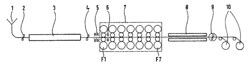
The hot rolling installation consists of a thin slab
casting line 1, whose strand guide can be controlled in such a
way that thin slab thicknesses of about 45 to 70 mm are obtained
at the outlet of the thin slab casting line 1. The continuously
cast thin slabs can be cut by a shear 2. The slabs can be
adjusted to lengths that correspond to the length of a finished
coil or a multiple thereof. The cut slabs are maintained at a
temperature of, e.g., 1,150 C in a roller hearth furnace 3 to
effect temperature equalization. The roller hearth furnace 3 is
followed by a shear 4, which is used only in the event of
damage.
The roller hearth furnace 3 is followed by a descaling
sprayer 5, which is followed by a seven-stand rolling train 7
with the rolling stands Fl to F7. The outlet of the rolling
train 7 is followed by a cooling line 8, which is followed in
the direction of strip flow by a flying shear 9, which is used
in the case of semicontinuous or continuous rolling. The hot
rolling installation ends with two coilers 10, which may be
CA 02456933 2004-02-04
alternatively designed as a rotary coiler.
An interstand descaling device 6 is positioned between
rolling stand Fl and rolling stand F2.
Depending on the material and the desired final
thicknesses, various rolling methods are possible:
If materials that are difficult to deform are to be rolled,
then the thin slab casting line 1 is adjusted in such a way
that, depending on the desired final thickness and casting
machine output, slabs with thicknesses of 45 to 70 mm, and
preferably 55 mm, are used. All seven stands Fl to F7 are
engaged. The interstand descaling device 6 is inactive. In
this type of operation, the high rolling forces and the large
amount of energy to be introduced into the difficultly
deformable material that is to be rolled make it possible to
achieve rolled strip thicknesses at the outlet of rolling stand
F7 of less than 1 mm, while a speed of about 15 m/s is not
exceeded, and yet rolled strip with austenitic microstructure is
obtained.
If readily deformable material is to be rolled to final
thicknesses > 1 mm, then thin slab thicknesses of 55 to 70 mm
are selected. All of the stands Fl to F7 are active, while the
6
CA 02456933 2004-02-04
interstand descaling device 6 is inactive.
During the rolling of readily deformable material with
final thicknesses below 1 mm, the thin slab casting line 1 must
be adjusted to thin slab thicknesses of 45 to 50 mm. The
rolling stand Fl is either inactive or engaged for a skin pass
with low reduction. The skin pass causes the slab surface to
become smoother, so that a more uniform layer of scale can
develop after the descaling sprayer 5. The active interstand
descaling device 6 can thus more easily remove the newly formed
scale, i.e., less descaling agent is applied to the slabs than
if the stand Fl were not adjusted for a skin pass.
The stands F2 to F7 are usually engaged slightly more
strongly than in the operation in which all seven stands are
engaged. As a result of the fact that only stands F2 to F7 are
operated, lower final rolling speeds are achieved. However, due
to the smaller entry slab thickness and the stronger engagement
of stands F2 to F7, final rolling thicknesses of less than 1 mm
are achieved, and the rolling stock has temperatures in the
austenitic microstructure range.
The hot rolling installation of the invention thus makes it
possible to roll both readily deformable and difficultly
7
CA 02456933 2004-02-04
deformable materials to thicknesses of less than 1 mm in the
austenitic range, without the delivery speed at rolling stand F7
exceeding 15 m/s. The entire process can thus be simply
designed, and the units of machinery of the hot rolling
installation, such as shears and coilers, retain their simple,
cost-effective design. Increased expenditure of work is not
necessary.
8
CA 02456933 2004-02-04
List of Reference Numbers
1. thin slab casting line
2. shear
3. roller hearth furnace
4. emergency shear
5. descaling sprayer
6. interstand descaling device
7. rolling train
8. cooling line
9. flying shear
10. coiler
9