Note: Descriptions are shown in the official language in which they were submitted.
CA 02457028 2004-02-12
WO 03/015952 PCT/US02/24949
PRESS BRAKE TOOL AND TOOL HOLDER
Field of the Invention
The invention relates to a press brake tool holder and a tool commonly
referred to as "American-style" tooling.
S Background of the Invention
Press brakes commonly are equipped with a lower table and an upper
table, one of which, commonly the upper table, is vertically movable toward
the
other table. Forming tools are mounted to the tables so that when the tables
are
brought together, a workpiece between the forming tables is bent into an
appropriate shape. It is common for the upper table to include a male forming
tool
having a bottom workpiece-deforming surface, usually V shaped, and for the
bottom table to have an appropriately shaped die having an upper surface
vertically aligned with the workpiece deforming surface of the tool so that
when
the tool and die are brought together, a workpiece between the two is pressed
by
I S the forming tool into the die and thus is given an appropriate bent shape.
It often
is necessary to exchange forming tools and dies when a different bending
operation is to be performed. The dies, commonly supported by the bottom table
of a press brake, are readily removed and exchanged for others. However, the
forming tools that usually are mounted to the upper table of a press brake
often
are not easily replaced. Forming tools usually are held by a C clamp or other
holder to the horizontally elongated upper table. Once the clamp has been
loosened, the forming tool can, in some instances, be removed downwardly, and
in others, must be removed by horizontally sliding it from the clamp. If a
long
forming tool is to be replaced, it becomes difficult to slide the forming tool
from its
clamp because of the proximity of neighboring clamps and forming tools; these,
in
turn, may themselves have to be removed in order to complete the tool exchange
process.
Because long forming tools can be quite heavy, when a clamp is loosened
to the point that the tool can be removed by moving it downwardly, a tool may
accidentally slip and fall, causing harm to press brake operators and
equipment.
An early press brake holder design is known as the "American style" and is
shown schematically in Figure 1A holding a common American-style press brake
tool. As shown in this figure, the bottom edge portion of the upper table is
so
fashioned as to accept a clamp C, and a heavy bolt is employed to attach the
CA 02457028 2004-02-12
WO 03/015952 PCT/US02/24949
2
clamp to the table. The press brake table and clamp respectively include
generally parallel, facing surfaces defining a downwardly open recess into
which
the tang T of a press brake tool is received. The bottom surfaces B of the
press
brake table and clamp commonly are horizontally aligned, and serve as load
bearing surfaces for transmitting a downwardly directed load onto the upwardly
facing shoulders S of a press brake tool. To mount the tool in the holder, the
tool
is pushed upwardly until its load receiving surfaces S encounters the load
transmitting surfaces B of the clamp and table, as depicted, and the bolt then
is
tightened to clamp the punch tool tang between the clamp and table.
From a manufacturing standpoint, the simplified design of the American-
style press brake tooling requires that the upwardly facing shoulders be
fairly
accurately horizontally aligned, but the tolerances on the height of the tang
of the
tool are relatively wide. As a result, long sections of American-style tooling
can be
manufactured, and when a press brake operator needs a particular length of
tooling, the appropriate length simply is cut from the long section and used
directly. When the tool is to be removed from the holder, the clamp C is
loosened
and the tool, firmly gripped by the press brake operator, is withdrawn
downwardly.
To avoid the possibility of accidental dropping of the tools, which can be
quite
heavy in long lengths, a strap can be attached to the top of the tang with the
edge
of the strap extending into a groove in the holder. However, with this
arrangement, the tool can be removed only by sliding it sideways from the
holder
or by disassembling the entire holder.
American-style tool holders thus are of a simple design having few moving
parts, and are relatively easy to use. Of the various types of press brake
tooling
and tool holders available, the American style is the most widely used and
remains a favorite.
Figure 1 B is a schematic side view of a press brake tool and tool holder
commonly referred to as a "European" or "Promecam" style. The press brake tool
itself has an upwardly extending tang T that is generally rectangular in cross
section and that has a safety groove extending along its length. Below the
safety
groove, the tool has an outwardly extending, upwardly facing shoulder S, and
the
tool extends downwardly from that shoulder to its workpiece-encountering edge.
CA 02457028 2004-02-12
WO 03/015952 PCT/US02/24949
3
European style tool holders commonly include a lip or edge that extends into
the
safety groove of the tool to restrain accidental dropping of the tool. As with
American-style tooling, the downwardly directed force of the ram is directed
against an upwardly facing shoulder or shoulders of the tool, rather than
against
the upper surface of the tang. Examples of European style tooling are shown in
U.S. patents 6,003,360 (Runk et al.) and 5,794,486 (Sugimoto et al.).
A third style of tooling, commonly referred to as Wila style tooling, is shown
in Figure 1 C. Reference also is made to U.S. Patent 5,245,854 for a
description
of this type of tooling and tool holder. The tool holder includes one or more
horizontally extending safety slots, and the tool itself includes a movable
projection that, in use, extends outwardly from a side wall of the tool into
the
safety slot. The upper end of the tang T of this tool style extends into force-
receiving contact with the tool holder; that is, the downward force of the
upper
table is transmitted directly to the upper surface of the tang.
European-style and Wila-style tool holders enable tools to be removed
downwardly from the holders. Although these tool holders have provided some
safety features to restrain a heavy tool from accidentally falling from the
tool
holder, no such system has been devised for the more popular American-style
tooling and tool holders. It will be understood that when small tools are
being
employed, the risk of injury from dropping the tool is not great, whereas when
longer and heavier lengths of tooling are used, the risk of injury resulting
from a
tool that unintentionally drops from the tool holder is substantially greater.
It would be valuable to provide tooling that would be adaptable for use in
American-style press brake tool holders, but that yet would offer the ability
to
loosen the clamp on the American-style tool holder without risking immediate
dropping of the tool.
Summary of the Invention
We have noted that, in American-style press brake tool holders, there
exists, in the downwardly open recess receiving the tool tangs, a shelf having
an
upwardly facing surface, and we have devised a tool having a safety key that
can
engage the upper surface of the shelf to restrain the tool from unintentional
CA 02457028 2004-02-12
WO 03/015952 PCT/US02/24949
4
dropping when the clamp is loosened, while not interfering with the transfer
of a
downwardly directed force from the upper table to the tool.
The present invention provides, in combination, a press brake tool and an
American-style press brake tool holder from which the tool can be removed
vertically rather than requiring the tool to be slid horizontally from the
holder. The
holder has a body with walls defining a downwardly open, tool-receiving recess
having a top, a downwardly facing, force-delivering shoulder adjacent the
bottom
of the recess, and a shelf within the recess having an upwardly facing surface
that
is spaced upwardly from the force-delivering shoulder. The tool comprises a
body
having a lower, work-engaging surface, an upwardly facing, force-receiving
shoulder that is engageable with the shoulder of the tool holder, and an
upwardly
extending tang that is receivable in the recess and that has an upper end that
is
spaced from the top of the recess. The tool includes a manually operable
actuator
that is spaced below the force-receiving shoulder of the tool so that it may
be
accessed and manually operated by a worker, and also a safety key that is
operatively coupled to the actuator. The safety key has a lower surface that
is
spaced above the upper end of the tang and that is engageable with the
upwardly
facing surface of the shelf. The key is movable horizontally into and out of
vertical
alignment with the shelf between locked and unlocked positions, respectively,
in
response to manual operation of the actuator. Thus, the current invention
makes
use of the shelf that is normally part of the American-style tool holder, and
does so
in a manner that provides a long-awaited safety solution to tool-dropping
problems
associated with this most popular press brake tool and tool holder combination
involving release and removal of a tool downwardly from the tool holder rather
than requiring removal by sliding the tool sideways in the tool holder.
Brief Description of the Drawing
Figure 1A is a schematic side view, partially broken away, of an American-
style press brake tool and tool holder;
Figure 1 B is a schematic side view, partially broken away, of a tool and tool
holder of the European style;
Figure 1 C is a schematic side view, partially broken away, of a Wila-style
tool and tool holder;
CA 02457028 2004-02-12
WO 03/015952 PCT/US02/24949
Figure 2 is a broken-away, cross-sectional view showing the side of an
embodiment of the invention; and
Figure 3 is a perspective, exploded view showing a tool of the invention.
Detailed Description of the Preferred Embodiment
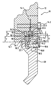
5 Figure 2 shows an American style press brake tool holder 10, the holder
including the lower portion 12 of a press brake upper table and a clamp 14
that
forms with the table portion a downwardly open recess 16. The clamp 14 is
pivotally attached, as at 14.1, to the table portion. A bolt 14.2, normally
accessible
from the front side of a press brake, secures the clamp to the table portion.
The recess 16 includes parallel opposing walls 16.1, 16.2 for reception of
the tang 18 of a press brake tool 20. Tang 18 has an upper end 18.1 that is
spaced below the top 16.3 of the downwardly open recess 16, as depicted.
As noted above, the downwardly open recess of American style tool
holders includes a shelf 16.3 offset slightly from that portion of the recess
that
I S receives the tang 18. The shelf 16.3 forms a shoulder that is generally
upwardly
facing and is spaced from the top 16.3 of the recess.
Referring now to Figure 3, the press brake tool 20 employed in the present
invention includes a body having at least one upwardly facing shoulder 18.2 on
one side of the tang, and preferably a similar, horizontally aligned shoulder
18.3
on the other side. These upwardly facing, force receiving shoulders come into
force transmitting contact with the force delivering shoulders 14.2, 12.1,
respectively, of the clamp 14 and upper table portion 12 adjacent the entry to
the
downwardly open recess 16. As the table descends in a bending operation, the
shoulders 18.2, 12.1 deliver a downwardly directed force onto the force
receiving
shoulders 18.2, 18.3, respectively, of the tool.
As shown in Figures 2 and 3, the press brake tool 20 of the invention
includes a safety key shown generally as 22. This key includes a shank 22.1
that
extends downwardly through a vertical bore 18.4 formed in the tang 18, the
bore
and the shank being so dimensioned as to enable to shank to have room for
freedom of movement within the bore in the direction shown by the arrow A in
Figure 3, that is, in a horizontal direction. The tool includes also a
horizontal bore
18.5 shaped to receive an actuator plunger 18.6, the latter having a threaded
CA 02457028 2004-02-12
WO 03/015952 PCT/US02/24949
6
distal end 18.7 configured to thread in to the threaded hole 22.2 of the key
22.
These elements are best seen with reference to Figure 3. The bore 18.5
includes
an outer, enlarged portion 18.8 (Figure 2) forming a spring seat, and a
helical
spring 18.9 is received about the plunger 18.6 and is captured between the
spring
seat and the enlarged head 19 of the plunger.
The safety key and plunger mechanism are assembled as shown in Figure
3. Following insertion of the shank 22.1 of the safety key downwardly into the
bore 18.1, the plunger 18.6, with spring 18.9 carried about its circumference,
is
inserted into the bore 18.5 and is pushed distally until its threaded end 18.7
encounters the threaded hole 22.2 of the safety key. An Allen wrench or other
tool is used then to thread the plunger into the hole 22.2 of the safety key,
locking
the safety key to the plunger. Note, in Figure 2, that the confronting,
generally
vertical surfaces of the safety key (adjacent threaded hole 22.2) and plunger
(adjacent its threaded end 18.7) come into surface-to-surface contact and thus
rigidly lock the safety key to the plunger with the vertical axis of the
safety key
held at approximately a right angle with respect to the axis of the plunger.
Finally,
a decorative button 19.1 may be fastened to the outer end of the plunger as
desired.
At its upper end, the safety key includes a protrusion 22.3 that extends
generally horizontally over the shelf 16.3 of the downwardly open recess 16.
To
assure freedom of movement of the safety key, the bottom surface 22.4 (Figure
2)
is spaced above the upper end 18.1 of the tang and is so configured as to
extend
over the upper surface of the shelf 16.3.
Note may be taken that the safety key protrusion 22.3 has an upper surface
22.5 which, as it extends toward the end of the protrusion, tapers downwardly
as
shown at 22.6.
When the tool and tool holder are assembled, as shown in Figure 2, the
respective force transmitting shoulders of the tool holder and the force
receiving
shoulders of the tool are in contact with each other, thus limiting and
defining the
extent to which the tang 18 extends upwardly into the recess 16. As
illustrated,
the top of the tang 18.1 is spaced substantially beneath the top 16.3 of the
recess.
Moreover, the downwardly facing surface 22.4 of the safety key protrusion is
at
CA 02457028 2004-02-12
WO 03/015952 PCT/US02/24949
. . ~, :. ~. ~ . .- ; . , .. :.
7
this point spaced above the upper end 18.1 of the tang and also the shelf
16.3.
This necessary clearance enables the safety key 22 to be moved horizontally
(to
the left in Figure 2) upon depression of the plunger 18.6 into the bore 18.5
against
the spring pressure of the spring 18.9. When the safety key protrusion has
been
moved far enough to the left to vertically clear the shelf 16.3 (and assuming
that
the bolt 14.2 has been sufficiently loosened), the tool can be removed
downwardly
from the tool holder. Note also must be taken that the upper end 22.5 of the
safety key is spaced beneath the top 16.3 of the recess.
Thus, to remove the tool from the tool holder, the bolt 14.2 is first
loosened.
This may enable the tool to slip downwardly slightly until the bottom surface
of the
safety key protrusion comes into contact with the shelf, preventing further
downward movement of the tool. A workman then grasps the tool, lifts the tool
upwardly slightly to space the bottom surface of the safety key protrusion
above
the shelf, and then pushes inwardly upon the plunger 18.6 to cause the safety
key
to move to the left in Figure 2. The tool can thus be removed downwardly with
a
degree of safety. When a tool such as that shown in Figures 2 and 3 is to be
remounted in the holder, the tool is pushed upwardly through the downwardly
open recess 16. The downwardly tapered surface 22.6 of the safety key
protrusion encounters the rim of the opening, and is cammed inwardly (to the
left)
slightly to enable the tang to be received in the recess. Preferably, the
plunger
18.6 is depressed during this operation. Once the tang has been received in
the
recess, further upward movement of the tool causes the downwardly facing
surface 22.4 of the safety key protrusion to horizontally clear the edge of
the shelf
16.3, and as the safety key thus is freed to move to its locked position, and
audible click commonly is heard. The elements, of course, are so dimensioned
that the force transmitting and receiving shoulders of the holder and tool do
not
come into contact during upward motion of the tool into the holder until the
safety
key has sprung to its locked position by the spring 18.9, as shown in Figure
2.
The relative dimensions of the tool and tool holder elements thus are of
importance. For example, the vertical distance (x) between the force receiving
surface of the tool to the lower surface of the safety key protrusion must be
greater than the vertical distance (y) between the force delivering surface of
the
CA 02457028 2004-02-12
WO 03/015952 PCT/US02/24949
8
holder and the upwardly facing surface of the shelf 16.3. Desirably, the ratio
x/y is
not less than about 1.01, preferably is not less than about 1.03, and most
preferably is in the range of about 1.01 to about 1.15. Moreover, the vertical
distance (p) from the force receiving surface of the tool to the top of the
tool holder
recess must be greater than the distance (q) from the force receiving surface
of
the tool to the top surface 22.5 of the key. Desirably, the ratio p/q is
greater than
about 1.1 and preferably is in the range of about 1.1 to about 1.3. Further,
the
vertical distance ( r ) between the upper surface of the shelf and the top of
the
recess must be greater than the vertical distance ( s ) between the top and
lower
surfaces of the safety key protrusion. Desirably, the ratio r/s is at least
about 1.7
and preferably is in the range of about 1.7 to about 2.4.
While a preferred embodiment of the present invention has been described,
it should be understood that various changes, adaptations and modifications
may
be made therein without departing from the spirit of the invention and the
scope of
the appended claims.