Note: Descriptions are shown in the official language in which they were submitted.
' CA 02457074 2004-02-12
WO 03/016629 PCT/EP02/07544
1
METHOD FOR THE CONTINUOUS LAYING OF A RAIL
ON A RIGID TRACK AS WELL AS RIGID TRACK
The present invention relates to a method for the
continuous laying of a rail on a rigid track consisting of
concrete slabs, in particular consisting of precast concrete
components, whereby the rail is placed in a channel of the
concrete slab and is then attached by filling in the
channel, as well as to a corresponding rigid track
consisting of a concrete slab.
l0 Rigid tracks consisting of precast concrete or
concrete cast on site are known. In a particular embodiment
of such rigid tracks a channel is provided on the top of the
concrete slab. The rail extends in the channel. For
extensive fastening of the rail in the channel, the rail is
cast in by means of an elastic casting material poured into
the channel. A system of this type is known by the name
Infundo.
In the state of the art it is disadvantageous in
some applications that the rail is fastened in the channel
by means of fasteners before the casting in of the rail. The
fasteners are cast-in together with the rail, even though
these are no longer needed to maintain the position of the
rail thanks to the poured mass. When rail-guided vehicles,
in particular high-speed trains travel over the rails, these
cast-in fasteners manifest themselves disadvantageously. The
oscillation of the rails is influenced at these locations so
that the travel comfort of the rail vehicle as well as the
wear of the rails are diminished.
For short-distance traffic it is especially
important that unimpeded traffic can be resumed rapidly
following construction work, especially at crossings of
streetcars and street. The solutions known so far are always
based on concrete tracks cast on site in which the rails are
laid. The production of the concrete slab on site as well as
' CA 02457074 2004-02-12
WO 03/016629 PCT/BP02/07544
2
the type of fastening of the rails within the concrete slab
produced on site as used until now require much time before
traffic can be resumed. It is therefore the object of the
present invention to improve travel comfort and wear
conditions with rigid tracks through suitable measures and
to create the possibility for especially rapid construction
of a rigid track especially in the area of short-distance
traffic.
This object is attained through the
l0 characteristics in the independent claims.
By a method for the continuous laying of a rail on
a rigid track, in particular one made of precast concrete
components, the rail is placed into a channel of the rigid
track and is fastened by filling the channel with poured
material. Filler blocks are placed on the sides of the rail
and the gap between the filler blocks and the channel sides
are filled with a grouting mortar. The filler blocks are
preferably installed together with the rail in the rail
channel of the precast slab. The grouting mortar achieves
the clamping of the filler blocks and thereby of the rail.
Contrary to the utilization of concrete cast on site, this
method makes it possible for the construction to progress
rapidly, i.e. when this method is used, crossings can be
produced within one day so that traffic would be able to
roll on this track as early as on the following day. This is
a great advantage, especially in case of reconstruction. The
advantage of a solution with precast parts and of continuous
rail laying are thus combined. The channels may be either
set on a slab or be integrated into the slab.
If the rails and/or the filler blocks are
installed by means of an alignment device, in particular
with wedges, within the channel in order to achieve precise
line positioning, this makes a very rapid and simple line
construction possible. The rails can be positioned in their
required position by means of the alignment device, in
CA 02457074 2004-02-12
WO 03/016629 PCT/8P02/07544
3
particular with wedges until the final positioning by means
of the grouting mortar lends them sufficient strength. The
alignment device may either remain in the channel and be
integrated with it by casting them in or, if the gap of the
alignment device has been left empty by casting, may be
removed from the channel. The empty gap in which the
alignment device had been located earlier can subsequently
be filled with the grouting mortar.
In order to achieve especially great strength of
the rail support it is possible to provide the rail with
conventional rail fasteners in addition to the fastening
with the filler blocks and the grouting mortar. In that case
the filler blocks may be softer, since they are not
exclusively responsible for the precise positioning of the
rail. The filler blocks may be designed in this case
optimally according to sound attenuation criteria.
In order to achieve especially good clamping of
the rails it is advantageous for the gap between the filler
blocks and the channel sides to be filled in with a grouting
mortar made of expansive cement. The expansive cement causes
the filler blocks to be clamped between the rail and the
channel sides. The elasticity of the filler blocks produces
an especially strong clamping of the rails because the
expansion of the cement presses the filler blocks against
the rail.
As is known in the high speed field precast
concrete slabs used for the rail traffic it is proposed
advantageously here according to the invention that also the
precast concrete slabs used for the short-distance rail
traffic be aligned in vertical and horizontal direction and
be then underpoured with a pouring mass, in particular
bitumen cement mortar. This makes a lasting fastening and
precise positioning of the rails possible. An especially
quiet and therefore noise-reduced traffic, e.g. of trolley
cars, is thus made possible.
' CA 02457074 2004-02-12
HIO 03/016629 PCT/BP02/07544
4
In order to achieve especially great precision of
the individual slabs relative to each other as well as of
the individual rails relative to each other, several precast
concrete slabs are coupled together throughout in
longitudinal direction. This coupling is achieved e.g. in
that threaded steel rods protrude from the slab ends and in
that these are coupled together by means of turnbuckles.
After or before the coupling, the gap between the precast
slabs is filled with cast concrete. The coupled precast
slabs provide especially quiet travel of the vehicle on the
rails. The subsidence of the subsoil beneath individual
precast slabs has a considerably lesser effect on the course
of the rails than when placing individual slabs.
Especially when the rigid track is installed in
the area of a rail/street crossing it is advantageous if the
precast concrete slab is covered with poured asphalt. This
allows for noise-reduction in the traffic at the crossing.
In a rigid track according to the invention made
of a concrete slab which is produced in an especially
advantageous manner in form of a precast concrete component,
the slab is provided with a channel in which the rail is
located, for the continuous laying of a rail. On the sides
of the rail filler blocks are provided. Wedges act upon the
filler blocks within the channel in order to maintain a
precise track line positioning. The gap between the filler
blocks and the channel sides are filled with grouting
mortar. Thereby precise and lasting positioning of the rail
on the precast concrete slab is achieved.
The rails and/or the filler blocks are installed
advantageously inside the channel with an alignment device,
in particular with wedges, in order to maintain a precise
positioning of the line. The wedges serve to fix the rail
temporarily in its predetermined position. The rail is
finally fixed in this position permanently by means of the
grouting mortar. In addition, the rail can be fastened by
' CA 02457074 2004-02-12
WO 03/016629 PCT/BP02/07544
means of conventional rail fasteners. These conventional
rail fasteners which normally clamp the rail base to the
channel bottom, possibly with an elastic intermediary layer,
are advantageously fastened only once the alignment device
5 holds the rail in the predetermined position.
If the gap between the filler blocks and the
channel sides is filled out with a grouting mortar made from
expansive cement, an especially advantageous fastening of
the filler bocks within the channel is achieved. The filler
l0 blocks are then pressed against the rails and thus produce
excellent sound attenuation as a vehicle passes over them.
The precast concrete slab is advantageously
aligned in vertical and horizontal direction and is
underpoured with a poured mass, in particular bitumen cement
mortar in order to achieve permanent fastening of the
precast concrete slab. If several precast concrete slabs are
coupled together throughout in longitudinal direction, a
very long-lasting, stable and strong track is also achieved
for short-distance rail traffic.
If the precast concrete slab is covered with
poured asphalt, a crossing can be produced very rapidly and
advantageously in one even plane. This furthermore makes it
possible for the precast concrete slab to be used also for
other than rail-guided vehicles. An advantageous line is
thus created especially for EMS vehicles. If the sides of
the channel and/or of the filler blocks towards the gap are
at an angle relative to the vertical axis of the rail, a
possible coming out of the filler blocks is prevented. Thus
an essentially trapezoid cross-section of the channel and/or
of the filler blocks is obtained. Possible coming out of the
filler blocks from the channel is prevented, since the
angled sides create undercuts with which the filler blocks
mesh.
In order to achieve a good wedging effect of the
alignment device it is advantageous for channel or filler
' ' CA 02457074 2004-02-12
WO 03/016629 PCT/8P02/07544
6
block sides towards the gap in the vicinity of the wedge are
essentially parallel with the vertical rail axis. In that
way the wedge can be fastened reliably and the rail can be
cast-in in the channel by pouring without changing its
position.
In order to be able to adjust the precast concrete
slab optimally in vertical and/or horizontal direction, the
precast concrete slab contains spindles. The precast
concrete slab is aligned by means of these spindles and is
underpoured thereafter for permanent fastening.
Especially when the present invention is applied
in the area of short-distance rail traffic it is
advantageous for the rail to be a groove rail, such as
normally used for trolley cars.
If the distance between the upper edge of the rail
and the upper edge of the slab is approximately 5 cm when
the slab is to be covered, the upper edge of the covering
can extend evenly with the upper edge of the rail. A
thickness of approximately 5 cm of the covering is normally
sufficient, especially if the covering is a layer of poured
asphalt. If the slab is not covered it is advantageous for
the upper edge of the rail to extend in one and the same
plane with the upper edge of the slab.
Especially if covered and uncovered slabs are to
be combined it is especially advantageous for the slab in an
embodiment with covering has approximately the same
thickness, together with the covering, as a slab in an
embodiment without covering. This makes it possible to
prepare a level foundation on which the two types of slabs
can be placed.
If the filler blocks are elastic, especially if
they are made of rubber granulate, an especially
advantageous clamping of the rails is achieved by means of a
cast concrete, especially if the latter is made of expansive
cement .
' CA 02457074 2004-02-12
WO 03/016629 PCT/SP02/07544
7
If the slab is rectangular or trapezoid in shape
the slabs can be used for curves or straight segments of the
line. The trapezoid form of the slab makes it possible to
lay the rails very easily within curve segments, especially
if the slabs for such applications are shorter than for
straight lines.
In a special embodiment of the present invention
the rigid track is a precast frame consisting of
longitudinal and transverse beams.
The longitudinal beams are in that case connected
to the transverse beams, whereby the transverse beams have
essentially the task of positioning the two longitudinal
beams. Overall a stable track is produced and can be made as
a precast component to be merely adjusted and installed on
the construction site. The frame of precast components is
lighter than the precast slab and is thus even easier to
lay. The wide gaps between the individual transverse beams
make greening of the track very easy. This too is especially
advantageous for inner-city traffic operation.
In such an embodiment of the precast concrete
component the rails are installed on or in the longitudinal
beams. The longitudinal beams may be designed so that they
contain a channel in which the rails are fastened.
Alternatively it is possible to provide for the rails to be
fastened on the longitudinal beams in a conventional manner
by means of rail fasteners at bearing points or
continuously.
To align the precast frame it is especially
advantageous for spindles to be provided in the more stable
longitudinal beams. The longitudinal beams and thereby the
precast frame is moved by means of the spindles into their
predetermined position. Following this, the longitudinal
beams are underpoured with an underpouring mass, in
particular a bitumen cement mortar in order to fasten the
precast frame permanently.
' CA 02457074 2004-02-12
WO 03/016629 PCT/8P02/07544
8
The rigid track is provided advantageously with an
opening essentially transversal to the longitudinal sense of
the rigid track, in the area of the channel. An alignment
device or part thereof is received at least temporarily in
the opening. In addition or alternatively, the opening
serves to produce or utilize a drainage groove for
precipitation water that accumulates between two parallel
humps or troughs of a rigid track.
Also if the rigid track is used for the
l0 conventional fastening of rails, the opening serves to
constitute a drainage groove and is thereby especially
advantageous and inventive. The applications of the rigid
track are thus extremely flexible.
The channel is advantageously located essentially
on a surface of the concrete slab. This facilitates
manufacture and makes it possible to produce a relatively
thin concrete slab that can be produced and transported
inexpensively because of its light weight.
If the opening in the channel reaches at least as
far as the slab surface it is possible for all of the
precipitation water accumulating on the slab surface between
the channels to flow off.
If the opening on the slab surface extends over
the entire width of the slab and is also continued
advantageously on the slab surface, the precipitation water
collects in the opening and runs off the rigid track through
the opening.
A gradient of the opening towards the outside of
the slab further assists the flowing off of the
precipitation water.
A rigid track where the rail is extensively cast
in into the trough is especially advantageous. This lends
especially great strength to the rail on the rigid track and
it is furthermore sound-insulated by the elastic casting
mass .
CA 02457074 2004-02-12
~O 03/016629 PCT/8P02/07544
9
The opening which can serve on the one hand to
contain the alignment device and on the other hand as a
drainage groove, can in addition serve as a target breaking
point of the slab for a defined crack formation. The opening
extending perpendicularly to the channels up to the slab
surface will then produce cracks at exactly these locations.
These defined cracks can be inspected easily and reliably to
determine the condition of the slab. If the crack occurrence
is too heavy, it may be necessary in some cases to consider
replacing the slab in question.
Additional advantages of the invention are
described in the examples of embodiments below.
Fig. 1 shows a rigid track with channels placed on
a slab surface,
Fig. 2 shows a rigid track with channels
integrated into the concrete slab,
Fig. 3 shows a rigid track with an alignment
device attacking from above,
Fig. 4 shows a detailed view of Fig. 3,
Fig. 5 shows a rigid track with alignment devices
attacking below the rail,
Fig. 6 shows a detailed view of Fig. 5,
Fig. 7 shows a precast concrete slab in
perspective,
Fig. 8 shows a detail of a rail fastening,
Fig. 9 shows a precast concrete slab with
covering, in perspective,
Fig. 10 shows a precast slab without covering, in
perspective,
Fig. 11 shows a precast concrete frame in
perspective and
Fig. 12 shows another precast concrete frame in
perspective.
In Fig. 1 a rigid track consisting of precast
concrete slabs 1 is shown in perspective. The precast
' ~ CA 02457074 2004-02-12
WO 03/016629 PCT/BP02/07544
concrete slab 1 consists essentially of a slab with a
substantially rectangular cross-section and with humps 2 set
on it . Two of the humps 2 constitute a channel 3 in which a
rail 4 is laid. The precast concrete slabs 1 are laid down
5 e.g. on a hydraulically attached supporting layer and their
position is determined e.g. by means of spindles that are
not shown. The precast concrete slab 1 is then underpoured
with an underpouring mass which is poured by means of
opening 6 between the precast concrete slab 1 and the
10 hydraulically attached supporting layer. The individual
precast concrete slabs 1 can be either placed loosely
against each other or can be coupled to each other in a
known manner. The humps 2 forming the channel 3 extend in
the longitudinal sense of the precast slabs. Two rails 4, 4'
constituting the rail line for rail-guided vehicles run
parallel to each other at a predetermined defined distance
from each other. The rails 4, 4' each of which is located in
a channel 3 are cast in with an elastic casting mass 5 in
the channel 3, and are thereby fastened permanently. Rails
other than those shown here can of course be used in the
same manner.
Fig. 2 shows another embodiment of a precast
concrete slab 1. The precast concrete slab 1 whose cross-
section is again substantially rectangular has parallel
incisions constituting in turn the channel 3. The precast
concrete slabs 1 are laid in the same manner as described
above for Fig. 1. The advantage of such a precast concrete
slab 1 is e.g. that it can be used for rail crossings, since
the line and the track bed can be traversed at a right angle
to the course of the rails.
Fig. 3 shows a precast concrete slab 1 as in
Fig. 1. The humps 2 and thereby the channels 3 extend above
the actual precast concrete slab 1. The channels 3 or humps
2 have openings 7 at regular intervals, extending at a right
angle to the longitudinal direction of the humps 2 and the
CA 02457074 2004-02-12
WO 03/016629 PCT/EP02/07544
11
channels 3. The openings 7 of a channel 3 correspond to the
openings 7 of the parallel channel 3'. An alignment device 8
is installed in the opening 7 connecting and thereby fixing
the two rails 4, 4' extending parallel to each other.
The alignment device 8 consists of two clamping
devices 10 as well as of a connection device 11 connecting
the two clamping devices 10 with each other. A level
alignment device 12 is provided in the area of each end of
the alignment device 8 or in the area of the rail 4, 4'. The
l0 vertical alignment of the rails 4, 4' is effected by means
of the level alignment device 12. In the present embodiment
the level alignment device 12 consists t of a spindle
supported on the bottom of the opening 7 and thus inflences
and fastens the rail 4, 4'.
When the alignment device 8 has been installed and
the adjustment of the rails 4, 4' has been effected, the
channel 3 can be cast in with an elastic casting mass 5. The
area of the alignment device 8 remains at first open, so
that the alignment device 8 can be removed once the casting
' 20 mass 5 has hardened to a great extent. At this point in time
the casting mass 5 already assumes the adjustment and
holding of the rail 4, so that the alignment device 8 is no
longer needed. Once the alignment device 8 has been removed,
the area in which it had previously been located in the
channel 3 can be filled with the casting mass 5 so that the
rail 4, 4' is completely cast in the casting mass 5. As a
result, no remaining alignment device 8 or parts thereof can
disturb the rail 4, 4' in its homogenous oscillation
behavior when a rail vehicle passes over it. The alignment
devices 8 are preferably placed at distances of 3 m each
from each other. Thereby sufficiently good adjustment of the
rails 4, 4' is made possible.
Fig. 4 shows a detailed view of the alignment
device 8 in the area of the clamping devices 10. The
alignment device 8 reaches around the rail 4 with its
' ~ CA 02457074 2004-02-12
WO 03/016629 PCT/$P02/07544
12
clamping devices 10. The rail 4 consists of a rail base 20,
a rail stem 21 and a rail head 22. The clamping devices 10
grasps the rail 4 in the present embodiment from the side of
the rail head 22 and clamps the rail head 22 and/or the rail
stem 21 in that a clamp 13 presses the rail 4 against a stop
14. The clamping force is imparted by means of a screw 15
that moves the clam 13 in the direction of the stop 14.
Extensive or complete unscrewing of the screw 15 makes it
possible to remove the clam 13 completely from the alignment
device 8, so that the alignment device 8 can be removed from
the partially cast in rail 4 by placing the alignment device
8 at an angle.
The level adjustment of the alignment device 8 is
effected by means of the level alignment device 12 that is a
spindle in the present embodiment. Rotation of the spindle
relative to the connection device 11 achieves vertical
adjustment of the alignment device 8 and thereby of the rail
4. The level alignment device 12 is supported for this on
the bottom of the openings 7. Alternatively it is also
possible for the level alignment device 12 to be supported
on the top of the hump 2 or even on the precast concrete
slab 1. In this case an for the stop 14 to be also movable,
so that a removal of the alignment device 8 from the
partially cast-in rail 4 becomes possible.
Fig. 5 shows another precast concrete slab 1. On
this precast concrete slab 1 humps 2 constituting a channel
3 are again provided on the slabs surface. On a precast
concrete slab 1 as in this embodiment, the openings 7 extend
into the area of the surface of the precast concrete slab 1.
The alignment device 8 extends in this embodiment below the
rails 4, 4' in the region of the precast concrete slab 1. As
the channel 3 is being cast in, the openings 7 can remain at
least partially open, so that precipitation water
accumulating between the two inner humps 2 is able to drain
off through these openings. In this manner especially easy
" ' CA 02457074 2004-02-12
WO 03/016629 PCT/8P02/07544
13
drainage of a rigid track is provided together with the
other advantages.
Fig. 6 shows a detailed view of the alignment
device 8 of the embodiment shown in Fig. 5. The alignment
device has a clamping devices 10 which clamps the rail 4
from the side of the rail base 20. As in the previous
example of an embodiment, the clamping devices 10 is
provided with a stop 14 as well as with a clamp 13. The
clamp 13 is in clamping or release position by means of a
screw 15. The horizontal distance between the rails 4, 4' is
obtained in that the connection device 11 is fixedly
connected to the stop 14. In this manner the same distance
between the rails 4, 4' from each other is always
maintained. The level adjustment in turn is made with the
level alignment device 12 which is again a spindle or a
screw. The level alignment device 12 is supported on the
bottom of the opening 7 and its level can be adjusted by
rotation. In some cases it may be necessary for the
connection device 11 or the stop 14 to be attached to the
alignment device 8 so as to be detachable at least in part
so that a removal of the alignment device 8 from the
partially cast-in rail 4 is made possible.
In the present embodiment the opening 7 reaches
into the precast concrete slab 1. As a result it is possible
in an especially advantageous embodiment of the invention to
use the openings 7 at the same time as a drainage groove if
the opening 7 is kept open below the rail 4 or the channel 3
as the area of the alignment device 8 of the channel 3 is
cast in. This can be effected by inserting a pipe in the
area of the alignment device 8 before the casting-in
operation, or by removing the casting mass again from the
opening 7 in the area below the rail 4 after the casting.
The opening 7 extending into the area of the
precast concrete slab 1 furthermore acts as a target
breaking location of the precast concrete slab 1. Crack
CA 02457074 2004-02-12
ia0 03/016629 PCT/EP02/07544
14
formation can be monitored exactly in the area of the
opening 7, so that the condition of the precast concrete
slab 1 can be determined quickly and easily and therefore
inexpensively at any time.
Fig. 7 shows a precast concrete slab 1 in a
perspective view. Channels 3 and 3' are provided in the
precast concrete slab 1, and in these the rails 4 which are
not shown here are fastened. The precast concrete slab 1 has
an opening 6 into which a casting mass, in particular
bitumen-cement mortar can be filled for the underpouring of
the precast concrete slab 1. The precast concrete slab 1 is
underpoured once the precast concrete slab 1 has been
aligned in vertical and/or horizontal direction by means of
spindles 18 several of which are installed in the slab 1. By
underpouring the slab 1 it is permanently fixed in its
predetermined position. Several slabs 1 can be connected
with each other by connecting to each other and bracing
threaded steel rods 19 protruding from the slab 1 with each
other. This is a connecting method such as is customary on
rigid tracks for high-speed rail traffic. With the present
invention, this technology is also used for short-distance
rail traffic, in particular trolley cars in inner city
operation.
The channels 3, 3' are designed so that the rails
4 can be fastened in an optimal manner. Conventional rail
fasteners 23 are provided for this and these advantageously
fasten the rails in a conventional manner on the slab 1 at
approximately 3 m intervals. The sides of the channels have
alternating recesses 25 and wedging surfaces 26. As shall be
described further on, the recesses 25 serve to fix the
inserted filler blocks within the channel. The undercut of
the recesses 25 prevents the filler blocks from gradually
coming out of the channel 3, 3'. An alignment device, in
particular wedges, are applied to the wedging surfaces 26 to
fasten the rail temporarily. Once the rail has been fastened
CA 02457074 2004-02-12
WO 03/016629 PCT/$P02/07544
permanently these wedges can be removed again and the
cavities can possibly also be cast-in with a casting mass.
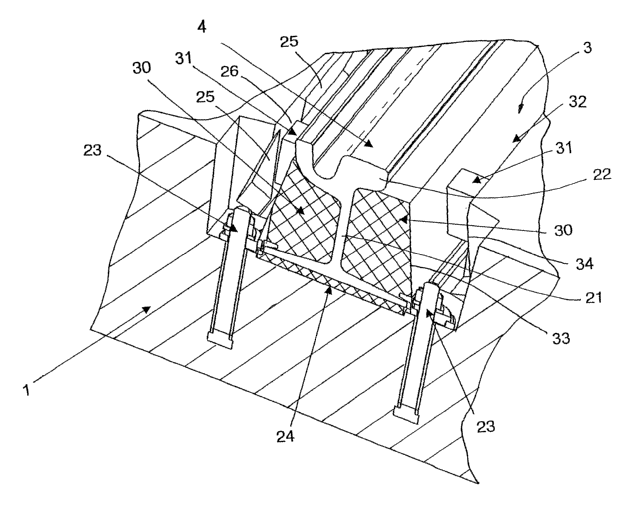
Fig. 8 shows a detailed view of a rail fastening.
The rail 4 is installed within the channel 3 of the precast
5 concrete slab 1. An elastic base 24 on which the rail 4 is
laid continuously is provided beneath the rail base 20.
Conventional rail fasteners 23 are applied to the rail base
and fasten the rail 4 essentially in its desired position
in vertical as well as in horizontal position. The rail
10 fasteners 23 are anchored inside the slab 1.
Filler blocks 30 are provided laterally at the
rail stem 21. The filler blocks 30 are ordinarily inserted
together with the rail 4 into the channel. In order to
achieve a fastening of the rail 4 between the rail fasteners
15 23, wedges 31 are provided to bear on the one hand against
the wedging surfaces 26 of the channel 3 and on the other
hand against a side 33 of the filler blocks 30. The side 33
is at an angle relative to the vertical axis of the rail 4
or of the wedging surfaces 26, so that the wedge 31 is able
20 to clampingly hold the filler block 30 inside the channel 3.
Between the filler blocks 30 and the sides 34 of the channel
3, in particular of the recesses 25 within the side 34, is
an interval 32 that is cast in with a mass not shown here.
This mass is made in particular of expansive cement and
fills out the interval 32 completely. The expansion causes
the advantageously elastic filler blocks 30 to be pressed
together, thus providing a permanent fixing of the rail 4
inside the channel 3. In addition, optimal noise insulation
of the rail is created. When the expansive cement has
hardened, the wedges 31 can be removed since they no longer
have any role to play. The cavities produced can also be
filled. Through the undercutting of the recesses 25 and the
also inclined cheek 33 of the filler blocks a wedging effect
on the filler blocks 30 is achieved, so that the filler
CA 02457074 2004-02-12
WO 03/016629 PCT/LP02/07544
16
blocks 30 are reliably prevented from coming out of the
channel 3.
Fig. 9 shows a precast concrete slab with covering
in perspective. The precast concrete slab 1 is designed so
that it is able to accept a covering 36. The upper edge of
the covering 36 is essentially flush with the upper edge of
the rail 4. As a result a level transition is created as is
required in particular with transverse traffic at crossings.
The covering 36 consists in many cases of poured asphalt, so
that street traffic can also pass over the precast concrete
slab 1.
Fig. 10 shows a perspective view of a precast
concrete slab 1 without covering. Compared with the precast
slab of Fig. 9, it appears that this precast concrete slab
without covering is thicker than the precast concrete slab 1
with the covering. Therefore the foundation of both slab
models can be prepared on the same level and these two slab
types can be combined without any further leveling of the
foundations.
Fig. 11 shows a precast concrete frame 38 in
perspective. The precast concrete frame 38 consists of two
longitudinal beams 38 and four transverse beams 39. The
rails 4, 4' are placed on the longitudinal beams 38. The
rails 4, 4' are fastened with conventional rail fasteners 23
located on bearing points. A precast concrete frame 37 as
shown in Fig. 11 has special advantages regarding weight and
thereby for processing. In addition it is possible to
provide greening between the longitudinal beams 38 so that
the utilization of such precast concrete frames 37 becomes
especially advantageous in inner-city rail traffic. In order
to achieve throughout greening or other covering between the
longitudinal beams 38, the height of the transverse beams 39
is less than the height of the longitudinal beams 38. The
precast concrete frame 37 is adjusted by means of spindles
18 integrated into the longitudinal beams of the precast
' ~ CA 02457074 2004-02-12
WO 03/016629 PCT/$P02/07544
17
concrete frame 37. Thereby an adjustment in horizontal and
vertical direction of the precast concrete frame 37 is
possible as much as with precast concrete slabs.
Fig. 12 shows another precast concrete frame in
perspective. Here the rails 4, 4' are not placed on the
longitudinal beams 38 but in channels 3, 3' of the
longitudinal beams 38. The rails 4, 4' can be fastened in
the channels 3, 3' either in the inventive manner described
above, or also in conventional manner. The fastening of the
rails 4, 4' can be continuous or discontinuous, standing or
hanging in this case. The upper edge of the rails 4, 4' is
advantageously flush with the upper edge of the longitudinal
beams 38. The upper edge of the longitudinal beams 38 may
however also be lower than the upper edge of the rails
4, 4', so that an additional covering can be added on it.
The present invention is not limited to the
embodiments shown. In particular different embodiments of
the alignment device and of the clamping device are possible
at any time. Combinations of the different embodiments are
also within the scope of the invention.