Note: Descriptions are shown in the official language in which they were submitted.
CA 02457480 2004-02-12
Q03018CA
~~-2~~~%~~~~~'Y ~'.~r,~p;~'°
TITLE OF THE INVENTION
A failure diagnosing apparatus for an engine cooling water
temperature sensor
BACKGROUND OF THE TNVENTION
The present invention relates to an apparatus for diagnosing failure
of a sensor that detects the temperature of cooling water of an internal
combustion engine.
A radiator mounted on a vehicle supplies cooling water to an
internal combustion engine (hereinafter referred to as "engine") to cool the
engine. A sensor for detecting temperature of the cooling water is provided
on the engine. This sensor will be hereinafter referred to as an "engine
water temperature sensor." The temperature detected by the engine water
temperature sensor is used for various controls of the engine. Appropriate
controls of the engine require accurate detection of the engine water
temperature.
Japanese Patent Application Unexamined Publication (Kokai) No.
2000-45851 shows a method for detecting a failure of the engine water
temperature sensor. According to the method, an output of the engine water
temperature sensor is monitored over a predetermined time period. If the
output of the sensor changes beyond a predetermined range, it is
determined that the sensor is normal. If changes in the output of the sensor
are within the predetermined range, it is determined that the sensor is
faulty.
According to a method shown in Japanese Patent Application
Unexamined Publication (Kokai) No. 2000-282980, an elapsed time after
the engine stops is measured. If an output of the engine water temperature
sensor is greater than a predetermined value when a predetermined time
has elapsed, it is determined that the engine water temperature sensor is
1
CA 02457480 2004-02-12
Q03018CA
stuck at a higher temperature level. When the engine starts before the
predetermined time elapses, an output of the engine water temperature is
obtained. If the obtained output is lower than a predetermined value, it is
determined that the engine water temperature sensor is stuck at a lower
temperature level.
When an elapsed time from the time when the engine stops in the
previous operating cycle is short and operating conditions of the engine are
similar to the previous operating cycle, an output of the engine water
temperature sensor may change little. In such a case, the conventional
methods may incorrectly determine a normal engine water temperature
sensor as being faulty.
The conventional methods require a timer for measuring an elapsed
time from the time when the engine stops. Providing such a timer leads to
an additional cost. Since detection of a failure of the engine water
temperature sensor requires that a predetermined time elapses after the
engine stops, the frequency of performing the failure detection process is
limited.
SUMMARY OF THE INVENTION
According to one aspect of the invention, a failure diagnosing
apparatus comprises a first sensor for detecting a temperature of cooling
water of an engine mounted on a vehicle and a second sensor for detecting a
temperature associated with the engine. In one embodiment, the second
sensor detects a temperature of air introduced into the engine. The failure
diagnosing apparatus is configured to calculate a first difference between a
temperature detected by the first sensor at the time when the engine stops
in a previous operating cycle and a temperature detected by the first sensor
at the time when the engine starts in a current operating cycle. The failure
diagnosing apparatus is further configured to calculate a second difference
2
CA 02457480 2004-02-12
QosolscA
between a temperature detected by the second sensor at the time when the
engine stops in the previous operating cycle and a temperature detected by
the second sensor at the time when the engine starts in the current
operating cycle. It is determined whether the first sensor is faulty based on
the first difference and the second difference.
According to the invention, since it can be determined whether
behavior of the first sensor is normal based on the comparison with
behavior of the second sensor, it can be prevented that a normal first sensor
is incorrectly determined as being faulty. Since both of the first and second
sensors are placed under the same external environment, the first sensor
exhibits a similar behavior to the second sensor if the first sensor is
normal.
By taking into account a behavior of the second sensor, it is more accurately
determined whether the behavior of the first sensor is normal. There is no
need to consider the influence of the external environment so as to
determine whether the behavior of the first sensor is normal.
A timer that measures an elapsed time after the engine stops is not
required, which leads to cast savings. Since the failure diagnosing process
can be performed before a predetermined time elapses from the time when
the engine stops, a limitation for the frequency of performing the failure
diagnosing process is relaxed.
According to one embodiment of the invention, the failure
diagnosing apparatus determines that the first sensor is faulty if a
magnitude of the first difference is Iess than a predetermined value when a
magnitude of the second difference is greater than a predetermined value.
An operating state may occur where the temperature of the cooling
water changes little even if the first sensor is normal. According to the
embodiment, in such an operating state, it is prevented that a normal first
sensor is erroneously determined to be faulty because the determination
that the first sensor is faulty is permitted if the amount of change in the
3
CA 02457480 2004-02-12
Q03018CA
output of the second sensor is relatively large.
In general, a vehicle comprises an intake air temperature sensor for
detecting a temperature of air introduced into the engine for various
control of the vehicle. Such an intake air temperature sensor can be used as
the second sensor. An additional sensor is not required for detecting a
failure of the first sensor.
According to one embodiment of the invention, the failure
diagnosing apparatus determines that the first sensor is normal if a
magnitude of the first difference is greater than a predetermined value.
Thus, normality of the first sensor is promptly detected without requiring
an output of the second sensor.
According to one embodiment of the invention, the failure
diagnosing apparatus prohibits the determination that the first sensor is
faulty if a magnitude of the first difference is less than a predetermined
value when a magnitude of the second difference is less than a
predetermined value.
The first sensor that exhibits a similar behavior to the second
sensor may be normal even if the amount of change in the output of the
first sensor is small. According to the embodiment of the invention, the
failure determination regarding the first sensor that exhibits such a
behavior is prohibited, thereby preventing making an erroneous
determination that a normal first sensor is faulty.
According to one embodiment of the invention, the failure
diagnosing apparatus permits the determination that the first sensor is
faulty if a possibility of a failure of the first sensor is detected in the
previous operating cycle.
BRIEF DESCRIPTION OF THE DRAWINGS
Figure 1 schematically shows an engine and its control unit in accordance
4
CA 02457480 2004-02-12
Q03018CA
with one embodiment of the present invention.
Figure 2 shows an exemplary behavior of an engine water temperature
and an intake air temperature after an engine stops.
Figure 3 shows an example of a relationship between the amount of
change in engine water temperature and the amount of change in intake
air temperature after the engine stops.
Figure 4 shows a functional block diagram of a failure diagnosing
apparatus for an engine water temperature sensor in accordance with one
embodiment of the present invention.
Figure 5 shows a flowchart of a process for diagnosing a failure of an
engine water temperature sensor in accordance with one embodiment of the
present invention.
Figure 6 is a flowchart of a process fox determining whether a
determination that an engine water temperature is faulty is permitted in
accordance with one embodiment of the present invention.
Figure 7 is a flowchart of another process for determining whether a
determination that an engine water temperature is faulty is permitted in
accordance with another embodiment of the present invention.
Figure 8 is a flowchart of another process fox' determining whether a
determination that an engine water temperature is faulty is permitted in
accordance with another embodiment of the present invention.
Figure 9 is a flowchart of another process for determining whether a
determination that an engine water temperature is faulty is permitted in
accordance with another embodiment of the present invention.
DESCRIPTION OF THE PREFERRED EMBODIMENTS
Referring to the drawings, specific embodiments of the invention
will be described. Figure 1 is a block diagram showing an engine and its
control unit in accordance with one embodiment of the invention.
5
CA 02457480 2004-02-12
Q03018CA
An electronic control unit (hereinafter referred to as an ECU) 5
comprises an input interface 5a for receiving data sent from each part of
the engine 1, a CPU 5b for carrying out operations for controlling each part
of the engine 1, a memory 5c including a read only memory (ROM) and a
random access memory (RAM), and an output interface 5d for sending
control signals to each part of the engine 1. Programs and various data for
controlling each part of the vehicle are stored in the ROM. A program for
performing a failure diagnosing process according to the invention, data
and tables used for operations of the program are stored in the ROM. The
ROM may be a rewritable ROM such as an EEPROM. The RAM provides
work areas for operations by the CPU 5a, in which data sent from each part
of the engine 1 as well as control signals to be sent out to each part of the
engine 1 are temporarily stored.
The engine 1 is, for example, an engine equipped with four cylinders.
An intake manifold 2 is connected to the engine 1. A throttle valve 3 is
disposed upstream of the intake manifold 2. A throttle valve opening (BTH)
sensor 4, Which is connected to the throttle valve 3, outputs an electric
signal corresponding to an opening angle of the throttle valve 3 and sends
the electric signal to the ECU 5.
A bypass passage 21 for bypassing the throttle valve 3 is provided in
the intake manifold 2. A bypass valve 22 for controlling the amount of air to
be introduced into the engine 1 is provided in the bypass passage 21. The
bypass valve 22 is driven in accordance with a control signal from the ECU
5.
A fuel injection valve 6 is installed far each cylinder at an
intermediate point in the intake manifold 2 between the engine 1 and the
throttle valve 3. A fuel injection valve 6 is connected to a fuel pump (not
shown) and is supplied with fuel from a fuel tank (not shown) via the fuel
pump. An opening time of each injection valve 6 is controlled by a control
6
CA 02457480 2004-02-12
Q03018CA
signal from the ECU 5.
An intake manifold pressure (Pb) sensor 8 and an intake air
temperature (Ta) sensor 9 are mounted in the intake manifold 2
downstream of the throttle valve 3. A pressure Pb of the intake manifold
and a temperature Ta of intake air introduced into the engine detected by
the PB sensor 8 and Ta sensor 9 are sent to the ECU 5, respectively.
An engine water temperature (Tw) sensor 10 is attached to the
cylinder peripheral wall, which is filled with cooling water, of the cylinder
block of the engine 1. A temperature of the engine cooling water detected by
the Tw sensor 10 is sent to the ECU 5.
A rotational speed (Ne) sensor 13 is attached to the periphery of the
camshaft or the periphery of the crankshaft (not shown) of the engine 1,
and outputs a CRK signal at a predetermined crank angle cycle (for
example, a cycle of 30 degrees). The cycle length of the CRK signal is
shorter than the cycle length of a TDC signal that is issued at a crank angle
cycle associated with a TDC position of the piston. Pulses of the CRK signal
are counted by the ECU 5 to determine the rotational speed Ne of the
engine.
An exhaust manifold 14 is coupled to the engine 1. The engine 1
discharges exhaust gas through the exhaust maxiifold 14. A catalyst
converter 15 installed at an intermediate point in the exhaust manifold 14
purifies undesired substances such as HC, CO and Nox contained in the
exhaust gas.
A full range air-fuel ratio sensor (LAF) sensor 16 is mounted
upstream of the catalyst converter 15. The LAF sensor 16 detects the
oxygen concentration in the exhaust gas in a wide air-fuel ratio zone, from
a rich zone where the air-fuel ratio is richer than the theoretical air-fuel
ratio to an extremely lean zone. The detected oxygen concentration is sent
to the E CU 5.
7
CA 02457480 2004-02-12
Q03018CA
A vehicle speed (VP) sensor 17 is mounted in the periphery of a
drive shaft (not shown) of the vehicle. A pulse that is issued from the VP
sensor 17 with each wheel rotation is sent to the ECU 5. The ECU 5
determines a vehicle speed based on the pulses from the VP sensor 17.
Signals sent to the ECU 5 are passed to the input interface 5a. The
input interface 5a converts analog signal values into digital signal values.
The CPU 5b processes the resulting digital signals, performs operations in
accordance with the programs stored in the ROM 5c, and creates control
signals. The output interface 5d sends these control signals to actuators for
a bypass valve 22, fuel injection valve 6 and other mechanical components.
Figure 2 shows an exemplary behavior of the engine water
temperature sensor 10 and the intake air temperature sensor 9 while the
engine stops. Reference number 26 shows a vehicle speed VP. During a time
period from t0 to tl, the engine is turned off and the outside air
temperature is almost flat as shown by reference number 29. After the
engine stops at time t0, the engine water temperature Tw slightly rises and
then gradually falls as shown by reference number 27. The intake air
temperature Ta rises and then gradually falls as shown by reference
number 28.
According to one embodiment of the present invention, when the
engine stops at time t0, the output Tw0 of the engine water temperature
sensor 10 and the output Ta0 of the intake air temperature sensor 9 are
stored in the memory 5c (Figure 1). When the engine starts at time tl, the
output Twl of the engine water temperature sensor 10 and the output Tal
of the intake air temperature sensor 9 are obtained.
If a difference between the engine water temperatures Tw0 and Twl
is greater than a predetermined value, it is determined that the engine
water temperature sensor 10 is normal.
If the difference between the engine water temperatures Tw0 and
8
CA 02457480 2004-02-12
Q03018CA
Twl is less than or equal to the predetermined value, it is determined
whether the engine water temperature sensor 10 is faulty based on the
amount of change in the output of the intake air temperature sensor 9.
Specifically, if a difference between the intake air temperatures Ta0 at time
t0 and Tal at time tl is greater than a predetermined value, it is
determined that the engine water temperature sensor 10 is faulty. If the
difference between the intake air temperatures Ta0 at time t0 and Tal at
time tl is less than or equal to the predetermined value, making the
determination that the engine water temperature sensor 10 is faulty is
l0 prohibited (or suspended).
The intake air temperature sensor 9 and the engine water
temperature sensor 10 are placed under the same external environment. If
the engine water temperature sensor is normal, the engine water
temperature exhibits a similar behavior to the intake air temperature. A
state where the engine water temperature Tw does not change although the
intake air temperature Ta changes indicates that the engine water
temperature sensor 10 is faulty. Since the amount of change in the intake
air temperature is taken into consideration to determine whether the
engine water temperature sensor is faulty, it is prevented that a normal
engine temperature sensor is erroneously determined to be faulty.
Alternatively, other temperature associated with the engine may be
used instead of the intake air temperature. For example, temperature of
the lubricating oil for the engine, temperature inside the engine
compartment, temperature inside the cylinder of the engine, or the like
may be used.
A failure of the engine water temperature sensor that is to be
detected by the failure diagnosing apparatus according to the invention
includes a condition where the sensor is "stuck." Such a condition where the
sensor is stuck indicates that the sensor is incapable of responding to any
9
CA 02457480 2004-02-12
Q03018CA
change in the actual engine water temperature, which may be caused, for
example, by a broken wire or a short-circuit.
Figure 3 shows an example of a relationship between the amount of
change in the engine water temperature Tw and the amount of change in
the intake air temperature Ta after the engine stops under different
environments. Data shown in Figure 3 is based on experiments performed
by the inventors of the present invention. A curve 31 shows a case where
0
the outside air temperature is 35 C . A curve 32 shows a case where the
outside air temperature is 25 ~ C . A curve 33 shows a case where the
outside air temperature is 15 ~ C . A curve 34 shows a case where the
outside air temperature is 10 Q C . A curve 35 shows a case where the
outside air temperature is 0 ~ C .
Reference number 41 shows an engine-stop point, which is
represented by a coordinate (TaO, Tw0). The intake air temperature Ta0
and the engine water temperature Tw0 obtained when the engine stops are
used as reference values. Each curve shows a relationship between the
amount of change relative to the reference value Ta0 and the amount of
change relative to the reference value TwO. For example, referring to the
curve 33, the intake air temperature rises and then falls after the engine
stops. When the intake air temperature Ta is lower than the reference
0
value Ta0 by 5 C, the engine water temperature Tw is lower than the
reference value Tw0 by 60 ~ C , as shown by a point 42.
A hatched area 43 indicates a sticking range where the engine water
temperature sensor may be stuck. If the engine water temperature Tw
changes beyond the sticking range 43, it is determined that the engine
water temperature sensor 10 is normal.
The inventors have realized that if the engine water temperature
sensor 10 is normal, the engine water temperature Tw surely changes
beyond the sticking range 43 while the intake air temperature Ta falls from
CA 02457480 2004-02-12
Q03018CA
the reference value Ta0 by a predetermined value (for example, ~ ~ C ) or
more. That is, if the engine water temperature sensor 10 is normal, the
engine water temperature Tw is surely out of the sticking range 43 when
the intake air temperature Ta enters into an allowable determination area
44. Thus, according to one embodiment of the invention, if the engine water
temperature ~v is within the sticking range when the intake air
temperature Ta enters into the allowable determination area 44, it is
determined that the engine water temperature sensor 10 is faulty.
0
The amount of change "-5 C" from the reference value Ta0 in the
intake air temperature shown in Figure 3, which defines the allowable
determination area 44, is one example. The amount of change in the intake
air temperature for defining the allowable determination area 44 may be
set to an appropriate value, for example, by carrying out an experiment or
simulation, in accordance with characteristics of the engine water
temperature sensor, the intake air temperature sensor and the engine.
The output of the engine water temperature sensor is converted to a
digital value. This digital value includes a noise that is caused, for
example,
by variations in the ground voltage level and the analog-to-digital
conversion process. Therefore, it is preferable that the width "w" relative to
the reference value ~v0 of the sticking range 43 is established considering
such noise. According to one embodiment of the present invention, the
width w is represented by a digital value having a predetermined number
of bits (for example, the width w has a digital value of 3).
As an example, it is assumed that the reference value ~v0 of the
engine water temperature is converted to a digital value of "3A'°. The
conversion can be performed in accordance with a predetermined rule. A
digital value that is lower by three than the digital value "3A" is
°'3?'°. If the
engine water temperature corresponding to a digital value lower than the
digital value "3?" is detected, it is determined that the engine water
11
CA 02457480 2004-02-12
Q03018CA
temperature sensor 10 is normal. For example, if the detected engine water
temperature is "33", it implies that the amount of change relative to the
reference value "3A" is seven, which is larger than the width w (3, in this
example). Therefore, the engine water temperature sensor 10 is determined
to be normal. By representing the width "w" by a digital value, the failure
diagnosing process performed by the ECU 5 is simplified.
In a case where the width w of the sticking range 43 is shown by a
digital value, a rule for converting an analog output of the engine water
temperature sensor to a digital value is specified considering the width w.
For example, it is assumed that the width w has a digital value of 3. Digital
values are assigned to analog sensor outputs in such a manner that a
failure of the engine water temperature sensor is surely detected when the
amount of change in the digital value to which the analog sensor output is
converted is less than or equal to three.
Figure 4 shows a block diagram of a failure diagnosing apparatus
for the engine water temperature sensor in accordance with one
embodiment of the present invention. Functions of the blocks are typically
implemented by computer programs that are stored in the memory 5c
(Figure 1). Alternatively, functions of the blocks may be implemented by
software, firmware, hardware or any combination thereof.
An operating condition detector 51 receives outputs from the intake
air temperature sensor 9 and the engine water temperature sensor 10. A
first difference calculator 52 calculates a first difference between the
engine
water temperature Tw0 at the time when the engine stops in a previous
operating cycle and the engine water temperature Twl at the time when
the engine starts in a current operating cycle. The first difference is
represented as an absolute value. A diagnosis unit 53 determines that the
engine water temperature sensor 10 is normal if the first difference is
greater than a first reference value. The first reference value corresponds
12
CA 02457480 2004-02-12
Q03018CA
to the width "w" relative to the reference value Tw0 of the sticking range 43
shown in Figure 3.
When the first difference is less than or equal to the first reference
value, a second difference calculator 54 calculates a second difference by
subtracting the intake air temperature Ta0 at the time when the engine
stops in the previous operating cycle from the intake air temperature Tal
at the time when the engine starts in the current operating cycle. If the
second difference is less than a second reference value, the diagnosis unit
53 determines that the engine water temperature sensor 10 is faulty. The
second reference value corresponds to the amount of change in the intake
air temperature that defines the determination allowable area 44 shown in
Figure 3. In the example of Figure 3, the second reference value is -5 ~ C .
The fact that the amount of change (Tal - Ta0) is less than the second
reference value implies that the intake air temperature has entered into
the allowable determination area 44.
One of the purposes of providing the second difference calculator 54
is to determine whether the intake air temperature has entered into the
allowable determination area 44. Those skilled in the art will recognize
that a calculation method performed by the second difference calculator 54
may be modified depending on how the allowable determination area 44 is
established.
According to one embodiment of the present invention, a failure
determination permitting part 55 is provided as shown in Figure 4. The
failure determination permitting part 55 determines whether
predetermined conditions for determining a failure of the engine water
temperature sensor are met. It should be noted that it is optional to provide
the failure determination permitting part 55.
During an operating cycle of the engine (that is, while the engine is
operating), the failure determination permitting part 55 detects a
13
CA 02457480 2004-02-12
Q03018CA
possibility of a failure in the engine water temperature sensor 10. A process
for detecting such possibility of a failure will be hereinafter referred to as
a
"possibility diagnosing process." The possibility diagnosing process
performed during an operating cycle is distinct from the failure diagnosing
process performed at engine start in accordance with the present invention.
If a possibility of a failure in the engine water temperature sensor 10 is
detected in the possibility diagnosing process, a flag FlgNG is set to a value
of one. It should be noted that the engine water temperature sensor is not
determined to be faulty during the possibility diagnosing process.
More specifically, in the possibility diagnosing process, the value of
one is set in the flag FIgNG if at Ieast one of the following conditions is
met
1) the engine water temperature does not change although the intake air
temperature changes
2) the engine water temperature does not change over a predetermined
time period and
3) the engine water temperature does not change although a predetermined
amount of heat from the engine is observed.
Additional or alternative conditions may be specified. For example,
in some cases, detecting a possibility of a failure in the engine water
temperature sensor may be inappropriate in light of vehicle speed, a
duration of time that an idle operation is performed, a duration of time that
a fuel-cut operation is performed, ar the like. In such cases, the value of
one
may be set in the flag FlgNG.
If any one of the following conditions is met, the flag FlgNG is set to
zero because the failure diagnosing process performed at engine start
according to the present invention may not be accurately performed under
such conditions:
i) when a failure of the intake air temperature sensor is detected and
ii) when another failure (for example, drift of the sensor) is detected in the
14
CA 02457480 2004-02-12
Q03018CA
engine water temperature sensor.
In an embodiment where the failure determination permitting part
55 is provided, if the second difference is less than the second reference
value and the value of one is set in the flag FlgNG, the diagnosis unit ~3
determines that the engine water temperature sensor 10 is faulty. If the
second difference is less than the second reference value and the value of
the flag FlgNG is zero, the diagnosis part 53 prohibits (or suspends)
determining that the engine water temperature sensor 10 is faulty. Thus,
when a possibility of a failure of the engine water temperature sensor is
detected in a previous operating cycle, making the determination that the
engine water temperature sensor is faulty is permitted in the failure
diagnosing process performed at the engine start of a current operating
cycle.
Alternatively, it may be determined in the possibility diagnosing
process that the engine water temperature sensor is faulty in response to
detection of a possibility of a failure of the engine water temperature
sensor.
In this case, if it is determined by the failure diagnosing process at engine
start according to the present invention that the sensor is normal, the
above "faulty" determination in the possibility diagnosing process is
canceled.
When the vehicle is traveling, changes in the intake air temperature
and the engine water temperature may become large depending on
operating conditions of the engine. On the other hand, since the failure
diagnosing process according to the present invention is performed at
engine start, the determination whether the sensor is faulty is made with
high reliability. Therefore, it is preferable to give priority to the
determination result obtained in the failure diagnosing process at engine
start of the current operating cycle according to the present invention
rather than the determination result obtained in the possibility diagnosing
CA 02457480 2004-02-12
C103018CA
process in the previous operating cycle.
In one embodiment of the present invention, if it is determined by
the failure diagnosing process at engine start that the engine water
temperature sensor is faulty, a warning light (MIL: malfunction indicator
light) may be turned on to inform a driver that an abnormal event has
occurred.
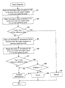
Figure 5 is an exemplary flowchart of a process for diagnosing a
failure of the engine water temperature sensor, which is performed by the
failure diagnosing apparatus shown in Figure 4. This process is performed
at the time when the engine starts. It is preferable that this process is
performed immediately after initial processes for various controls at engine
start are completed.
In step S1, the engine water temperature Tw0 at the time when the
engine stopped in a previous operating cycle is read out from the memory
5c (Figure 1). In step S2, the engine water temperature Tw1 at the time
when the engine starts in a current operating cycle is obtained from the
engine water temperature sensor 10.
In step S3, a difference between the engine water temperatures Tw0
and Twl is calculated. It is determined whether the difference is greater
than the first reference value. If the difference is greater than the first
reference value, it implies that the engine water temperature has changed
beyond the sticking range 43 (Figure 3). In step S4, it is determined that
the engine water temperature sensor 10 is normal.
In one embodiment of the present invention, the first reference
value corresponds to the width "w" relative to the reference value Tw0 of
the sticking range 43 as described above. The width w can be represented
by a digital value having a predetermined number of bits (for example, w
has a digital value of 3). In this case, if the difference between two digital
values Tw0 and Tw1 is greater than the digital value of 3, it is determined
16
CA 02457480 2004-02-12
l103018CA
that the engine temperature sensor 10 is normal.
If the difference between Tw0 and Twl is less than or equal to the
first reference value, the process proceeds to step S5. In step S5, the intake
air temperature Ta0 at the time when the engine stopped in the previous
operating cycle is read out from the memory. In step S6, the intake air
temperature Ta1 at the time when the engine starts in the current
operating cycle is obtained from the intake air temperature sensor 9.
in step S7, it is determined whether the intake air temperature has
entered into the allowable determination area 44. In this embodiment, the
difference is calculated by subtracting the intake air temperature Ta0 from
the intake air temperature Ta1 and then it is determined whether the
calculated difference is less than the second reference value. The second
reference value corresponds to the amount of change in the intake air
temperature for defining the allowable determination area 44. In the
example shown in Figure 3, the second reference value is "-5 ~C ." If the
difference is less than the second reference value, it implies that the intake
air temperature has entered into the allowable determination area 44. The
process proceeds to step S8.
In step S7, if the difference is greater than or equal to the second
reference value, there is a possibility of making an inaccurate diagnosis
because the intake air temperature has not entered into the allowable
determination area 44. Therefore, making the determination that the
sensor is faulty is suspended in step 510.
In step S8, the flag FlgNG is examined. If FlgNG=l, it implies that
other conditions for making the determination that the engine water
temperature sensor is faulty are met in the previous operating cycle. In
step S9, it is determined that the engine water temperature sensor is faulty.
If FlgNG=0, the determination that the engine water temperature sensor is
faulty is suspended (S10).
17
CA 02457480 2004-02-12
Q03018CA
Figure 6 is an exemplary flowchart of a process for permitting
determining whether the engine water temperature sensor is faulty
according to one embodiment of the invention. This process is performed by
the failure determination permitting part 55. This process is performed at a
constant time interval during an operating cycle of the engine. In this
process, it is determined whether the above-described condition 1) is met.
In step 511, the engine water temperature Tw2 at the time when
the engine starts is read out from the memory 5c (Figure 1). In step 512, a
current engine water temperature Tw is obtained from the engine water
temperature sensor 10.
In step 513, a difference between the engine water temperatures Tw
and Tw2 is calculated. It is determined whether the difference is greater
than the first reference value: If the difference is greater than the first
reference value, it implies that the engine water temperature has changed
beyond the sticking range 43 (Figure 3). In step 514, it is determined that
the engine water temperature sensor 10 is normal. The first reference value
is the same as in step S3 of Figure 5. If the difference is less than or equal
to the first reference value, the process proceeds to step 515.
In step 515, the intake air temperature Ta2 at the time when the
engine starts is read out from the memory. In step 516, a current intake air
temperature Ta is obtained from the intake air temperature sensor 9.
In step 517, a difference between the intake air temperatures Ta
and Ta2 is calculated. It is determined whether the difference is greater
than a predetermined value. If the difference is greater than the
predetermined value, it implies that the engine water temperature does not
change although the intake air temperature changes. This indicates that
there is a possibility of a failure in the engine water temperature sensor 10.
In step 518, a value of one is set in the flag FlgNC. If the difference is
less
than or equal to the predetermined value, it implies that there is a
18
CA 02457480 2004-02-12
Q03018CA
possibility of making an erroneous determination regarding a failure of the
sensor. In step 519, the flag FIgNG is set to zero.
Figure '7 is a flowchart of a process for permitting determining
whether the engine water temperature sensor is faulty, according to
another embodiment of the invention. This process is performed at a
constant time interval during an operating cycle. In this process, it is
determined whether the above-described condition 2) is met.
Processes in steps S21 through S24 are the same as in steps S11
through 514.
In step 525, an elapsed time (from the time when the engine starts,
for example) is measured by incrementing a timer. In step 526, it is
determined whether a predetermined time has elapsed. If the difference
between the engine water temperatures Tw and Tw2 is less than or equal to
the first reference value when the predetermined time has elapsed, it
implies that the engine water temperature does not change far the
predetermined time. This indicates a possibility of a failure in the engine
water temperature sensor 10. Instep 527, the flag FIgNG is set to a value
of one. If the predetermined time has not elapsed, the process terminates.
Figure 8 is a flowchart of a process for permitting determining
whether the engine water temperature sensor is faulty, according to yet
another embodiment of the invention. This process is performed at a
constant time interval during an operating cycle. In this process, it is
determined whether the above-described condition. 3) is met.
Processes in steps S31 through S34 are the same as in steps S11
through 514.
In step 535, the amount of heat from the engine is calculated. For
example, the amount of heat may be approximated by the amount of fuel
injected per unit time. The amount of fuel injected per unit time is
calculated in accordance with "the basic amount of injected fuel TIM x the
19
CA 02457480 2004-02-12
fa03018CA
frequency of a fuel injection operation per unit time". The basic amount of
injected fuel TIM indicates the amount of fuel injected at a time by the fuel
injection valve 6 (Figure 1), which is typically determined based on the
engine rotational speed NE and the intake air manifold pressure Pb. The
frequency of a fuel injection operation per unit time can be determined
based on the engine rotational speed NE.
In step 536, the heat amount Q thus calculated in step S35 is added
to the previous value QTTL(k-1) of the accumulated amount of heat, to
obtain the current value (~TTL(k) of the accumulated amount of heat. Here,
"k" indicates an identifier for identifying a cycle. Thus, the accumulated
amount of heat over a predetermined time period is obtained.
In step 537, if the accumulated amount (~TTL of heat is greater
than a predetermined value, it implies that the engine water temperature
does not change although the amount of heat from the engine is large. This
indicates a possibility of failure in the engine water temperature sensor 10.
In step 538, the flag FlgNG is set to a value of one. If the accumulated
amount QTTL of heat is less than or equal to the predetermined value, the
process terminates.
Figure 9 shows a flowchart of a process that is an improved version
of the process shown in Figure 6 for permitting determining whether the
engine water temperature sensor is faulty. This process differs from Figure
6 in that step S13 is replaced with steps S41 through 545.
If the current engine water temperature Tw is greater than a
maximum value that is stoxed in the memory 5c (S41), the maximum value
is updated with the current engine water temperature Tw (S42). If the
current engine water temperature Tw is less than a minimum value that is
stored in the memory 5c (S43), the minimum value is updated with the
current engine water temperature Tw (S44). In step 545, a difference
between the maximum value and the minimum value is calculated. It is
CA 02457480 2004-02-12
Q03018CA
determined whether the difference is greater than the first reference value.
By examining the maximum and minimum values, the amount of change in
the engine water temperature that is surely detected by the engine water
temperature sensor 10 is more accurately obtained.
Each of step S23 in Figure 7 and step S33 in Figure 8 may be
replaced with steps S41 through S45 shown in Figure 9.
The invention may be applied to an engine to be used in a
vessel-propelling machine such as an outboard motor in which a crankshaft
is disposed in the perpendicular direction.
21