Note: Descriptions are shown in the official language in which they were submitted.
CA 02457497 2004-02-06
WO 03/017908 PCT/US02/27041
-1-
INTEGRATED SCALE WITH UNDERLYING X-RAY TRAY
The present invention relates to infant supports for incubators or infant
warmers or combinations thereof, the support providing an integrated scale for
weighing the infant, a tilt mechanism for tilting the infant and a receptor
for an x-ray
tray below the infant.
Infant care equipment such as incubators or infant warmers are well
known in the prior art. U.5. patents as follows show exemplary incubators and
warmers:
U.S. PATENT ISSUED
4,221,211 Sep. 9, 1980
4,492,279 Jan. 8, 1985
4,617,912 Oct. 21, 1986
4,750,474 Jun. 14, 1988
5,290,058 Mar. 1, 1994
5,376,761 Dec. 27, 1994
5,453,077 Sep. 26, 1995
5,474,517 Dec. 12, 1995
5,817,002 Oct. 6, 1998
5,971,914 Oct. 26, 1999
6,071,228 Jun. 6, 2000
6,155,970 Dec. 5, 2000
The above listed exemplary patents show or disclose incubators or
baby warmers with weighing scales or with x-ray trays. The references are
incorporated herein for purposes of establishing the nature of incubators,
warmers, x-
ray trays, and weight scales. For example, patent 4,221,211 shows an x-ray
tray
incorporated into an incubator. Patent 4,492,279 shows the details of a weight
cell or
scale for weighing infants. Patent 5,453,077 discloses how an x-ray cartridge
may be
inserted underneath a mattress for taking x-rays of an infant.
An integrated scale and x-ray tray for use in a combination radiant
heater and incubator of the type shown in patents 5,817,002 and 5,971,914 is
described. The integrated scale integrates both a weighing scale feature and
an x-ray
CA 02457497 2004-02-06
WO 03/017908 PCT/US02/27041
-2-
tray feature for use in an infant support for either an incubator or an infant
warmer or
a combination incubator and infant warmer.
Accordingly, there is provided an infant support for an incubator or
infant warmer or a combination thereof, the support comprising a frame, a
mattress
tray disposed above the frame, an x-ray tray, and one or more weight cells.
The
mattress tray, which supports a mattress for an infant thereon, is supported
on the
frame by the one or more weight cells. The frame provides a space therebelow
for
receiving an x-ray tray below the frame, mattress tray and infant supported on
the
mattress tray and more particularly on a mattress provided on the mattress
tray.
Typically, the mattress tray and frame will be made from an x-ray translucent
material
such as plastic material. The mattress tray and frame each have a head end, a
foot
end, and longitudinally extending sides. The x-ray tray is movable
transversely into
and out of the space under one side of the frame, although it will be
appreciated that
the x-ray tray may be movable into and out of the space under either side of
the frame.
In one illustrative embodiment, to support the x-ray tray, the frame provides
longitudinally spaced, transversely extending tracks depending from the frame
to
slidably receive the x-ray tray. These tracks, which may be formed on the
downwardly facing surface of the frame, and illustratively formed as part of
the
frame, provide longitudinally spaced apart, upwardly facing tracks on which
the x-ray
tray slides. The x-ray tray may illustratively be provided with side portions
configured to engage the tracks.
In one illustrative embodiment, the mattress tray is mounted for
vertical movement on the frame, and the one or more weight cells are disposed
on the
frame to provide an output corresponding to the weight of the mattress tray
plus the
infant or accessories carried by the mattress tray. The frame illustratively
has a head
end, a foot end and longitudinally extending sides defining four corner
portions.
Illustratively, a weight cell is attached to the underside of the frame at
each of the four
corners and a actuator is provided to extend upwardly through apertures in
each
corner portion of the frame. The mattress tray has its four corner portions
above the
frame corner portions, and the mattress tray illustratively has openings for
receiving
the actuators extending from the frame corner portions therebelow.
CA 02457497 2004-02-06
WO 03/017908 PCT/US02/27041
-3-
Illustratively, there is provided one weight cell disposed in association
with each actuator and the actuator is coupled to a sensor supporting the
mattress tray
thereabove.
In a second embodiment, there is provided an infant support for an
incubator or infant warmer or a combination thereof, the support comprising a
frame,
a mattress tray disposed above the frame, an x-ray tray, and one or more
weight cells.
The mattress tray, which supports a mattress for an infant thereon, is
supported on the
frame by the one or more weight cells. The frame and the mattress tray provide
a
space therebetween for receiving an x-ray tray below the mattress tray to be
below the
infant supported on the mattress tray and more particularly on a mattress
provided on
the mattress tray. Typically, the mattress tray will be made from a plastic
material.
The mamess tray has a head end, a foot end, and longitudinally extending
sides. The
x-ray tray is movable transversely into and out of the space under one side of
the
mattress tray, although it will be appreciated that the x-ray tray may be
movable into
1 S and out of the space under either side of the mattress tray. In the second
illustrative
embodiment, to support the x-ray tray, the mattress tray provides
longitudinally
spaced, transversely extending tracks depending from the mattress tray to
slidably
receive the x-ray tray. These tracks, which may be formed on the downwardly
facing
surface of the mattress tray, and illustratively formed as part of the
mattress tray,
provide longitudinally spaced apart, upwardly facing tracks on which the x-ray
tray
slides. The x-ray tray may illustratively be provided with side portions
configured to
engage the tracks.
In the second illustrative embodiment, the mattress tray is mounted for
vertical movement on the frame, and the one or more weight cells are disposed
on the
frame to provide an output corresponding to the weight of the mattress tray
plus the
infant or accessories carned by the mattress tray. The frame illustratively
has a head
end, a foot end and longitudinally extending sides defining four corner
portions. A
post is provided to extend upwardly from each corner portion of the frame. The
mattress tray has its four corner portions above the frame corner portions,
and the
mattress tray illustratively has openings for receiving the posts on the frame
corner
portions therebelow. The mattress tray will move freely upwardly and
downwardly as
guided by the corner posts.
CA 02457497 2004-02-06
WO 03/017908 PCT/US02/27041
-4-
Illustratively, in the second embodiment, there is provided one weight
cell disposed in association with each corner post, each weight cell
comprising an
upstanding sensor supporting the mattress tray thereabove.
Additional features, and advantages of the invention will become
apparent to those skilled in the art upon consideration of the following
detailed
description of the preferred embodiment exemplifying the best mode of carrying
out
the invention as presently perceived.
BRIEF DESCRIPTION OF THE DRAWINGS
Fig. 1 is a perspective view of a combination infant incubator and
radiant warmer in an intermediate configuration between the incubator
configuration
and the radiant warmer configuration showing side panels of the infant
enclosure
lowered to reveal a first embodiment of an integrated scale assembly with a
first
embodiment of a mattress tray;
Fig. 2 is a partially exploded view of the combination infant incubator
and radiant warmer with the canopy and side panels removed showing the head
and
platform base assembly with T-bars of a Trendelenberg mechanism extending
through
the upwardly facing surface of the base and showing the first embodiment of
the
integrated scale assembly with a second embodiment of the mattress tray;
Fig. 3 is a partially exploded perspective view of the Trendelenberg
mechanism assembly of Fig. 2 rotated 90 degrees and with the T-bars removed;
Fig. 4 shows an exploded perspective view of the first embodiment of
the integrated scale assembly comprising a frame, the first embodiment of the
mattress tray, and an x-ray tray to be inserted into a channel formed in the
underside
of the frame;
Fig. 5 is a fragmentary sectional view taken along line 5-5 of the
assembled assembly of Fig. 4 along line 5-5;
Fig. 6 is a bottom plan view of a corner of the frame with the T-bar of
the tilt assembly supporting the frame and a weight cell mounted to the frame;
Fig. 7 is a bottom perspective exploded view of a corner of the second
embodiment of the mattress tray showing rings attached to the bottom surface
of the
tray to receive actuators extending from a weight cell;
CA 02457497 2004-02-06
WO 03/017908 PCT/US02/27041
-5-
Fig. 8 is an end elevation view of the second embodiment of the
mamess tray with parts broken away and the frame showing a weight cell in
phantom
lines;
Fig. 9 shows an exploded perspective view of an illustrative weight
cell;
Fig. 10 is a bottom plan view of the x-ray tray received in the frame
supported by the T-bars of the Trendelenberg mechanism assembly;
Fig. 11 is a partial sectional view along line 11-11 of Fig. 10;
Fig. 12 is a partial sectional view along line 12-12 of Fig. 10;
Fig. 13 shows an exploded perspective view of a second embodiment
of an integrated scale assembly comprising a subframe, a mattress tray, and an
x-ray
tray to be inserted into the space between the subframe and the mattress tray:
Fig. 14 is a perspective view showing the components of Fig. 13
assembled together;
Fig. 15 is a fragmentary sectional view showing an end portion of the
assembly in Fig. 14; and,
Fig. 16 is a view of the x-ray tray assembly.
DETAILED DESCRIPTION OF THE ILLUSTRATED EMBODIMENTS
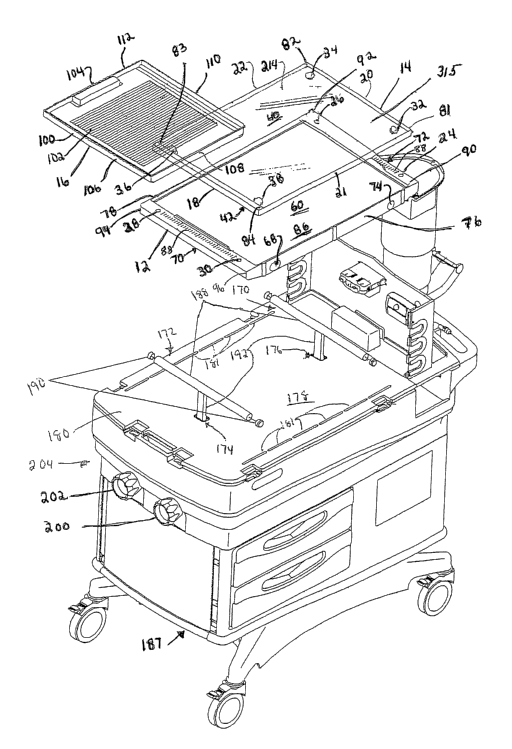
A first embodiment of an integrated scale for an infant care system 8
comprises an assembly 10 shown in Figs. 1, 2 and 4-8, and particularly in Fig.
4. The
assembly comprises a frame 12, a mattress tray 14 and an x-ray tray 16. In the
illustrated embodiment, the infant care system 8 is a combination incubator
and
radiant warmer capable of acting as a standard incubator in a first
configuration and as
a standard radiant warmer in a second configuration.
Fig. 1 depicts the infant care system 8 in a configuration with one side
panel 160 lowered to show the assembly 10. When infant care system 8 is in an
incubator configuration, an overhead arm 162 is lowered so that a canopy 164
attached thereto can cooperate with the side panels 160 and end panels 166 to
form an
enclosure around the infant. A controlled environment can be provided in the
enclosure by circulating warmed and treated air within the enclosure. When
infant
care system 8 is in a warmer configuration, overhead arm 162 is raised, and a
radiant
CA 02457497 2004-02-06
WO 03/017908 PCT/US02/27041
-6-
heater therein provides warmth to the infant on the infant support. In this
configuration, much greater access is provided to the infant for treatment and
care.
In either configuration, by lowering an appropriate side panel 160,
access can be gained to x-ray tray 16 of integrated scale assembly 10 for
insertion and
removal of an x-ray film cassette 159. Typically, x-rays of the infant will be
taken
with the overhead arm 162 raised to the second position. While the invention
is
described and depicted as being utilized in a combined infant incubator and
radiant
warmer, it is within the scope of the disclosure for the integrated scale
assemblies 10,
310 to be used in standard incubators, standard radiant warmers, and other
infant
support devices.
The illustrated embodiments of integrated scale assemblies 10, 310 are
configured for use with an infant support device 8 having a Trendelenberg
mechanism
assembly 168. In the drawings, only the first embodiment of integrated scale
assembly 10 is shown mounted on the Trendelenberg or tilt mechanism assembly
168.
However, those skilled in the art will recognize that both first and second
embodiments of integrated scale assembly 10, 310, respectively, include
similar
structural components identified by similar reference numerals to facilitate
mounting
of scale assemblies on Trendelenberg mechanism assembly 168. Thus, the manner
of
mounting of integrated scale assembly on Trendelenberg mechanism assembly 168
is
described with respect to first embodiment of integrated scale assembly 10
only.
Nevertheless, those skilled in the art will recognize that integrated scale
assembly 310
is configured for similar mounting on Trendelenberg mechanism assembly 168.
Trendelenberg mechanism assembly 168 is configured to permit an
integrated scale assembly 10 mounted thereon, the mattress (not shown)
supported on
the mattress tray 14 and an infant supported on the mattress, to be placed in
a flat
position, Trendelenberg position or reverse-Trendelenberg position. The
illustrated
Trendelenberg mechanism assembly 168, as shown, for example, in Fig. 3,
includes
two T-bars or lift bars, a head lift bar 170 and a foot lift bar 172,
extending upwardly
through openings 174, 176 in an upwardly facing surface 178 of a ducted cover
180
and openings 182, 184 of mechanism cover 186 of base 187 of infant support 8.
Each
T-bar 170, 172 is independently movable vertically with respect to upwardly-
facing
surface 178 of cover 180. Each T-bar 170, 172 includes a horizontally
extending bar
CA 02457497 2004-02-06
WO 03/017908 PCT/US02/27041
_7_
188 having caps 190 attached to each end of bar 188 and a shaft 192 extending
vertically downwardly from the center of horizontally extending bar 188.
Horizontally extending bar 188 is received in lift bar-receiving channels 69,
75 of
frame 12 as shown in Figs. 1, 6, 10, 11, 12 as will be explained in further
detail
hereafter.
As shown, for example, in Figs. 2 and 3, Trendelenberg mechanism
assembly 168 includes a head tilt mechanism assembly 194 and a foot tilt
mechanism
assembly 196 mounted to base 187 of infant support 8 below openings 174, 176,
182,
184 in covers 180, 186, respectively. Each tilt mechanism assembly 194, 196
includes an opening 198 into which shaft 192 of a T-bar 170, 172 is received.
Head
and the foot tilt mechanism assemblies 194, 196 permit horizontally extending
bars
188 of head and foot T-bars 170, 172 to be raised and lowered independently
through
reciprocal movement of shaft 192 within tilt mechanism assembly 194, 196.
Thus, tilt
mechanisms 194, 196 allow frame 12 supported on horizontally extending bars
188,
1 S mattress tray 14 supported above frame 12, the mattress (not shown)
supported on
mattress tray 14 and the infant supported on the mattress to be positioned in
a flat
position, Trendelenberg position and reverse Trendelenberg position.
Illustratively, independent adjustment of head and foot T-bars 170, 172
is accomplished by a caregiver turning head and foot adjustment knobs 200,
202,
respectively, which extend from foot end 204 of infant support 8.
Illustratively, shafts
206, rings 208, washers 210, compression springs 212, cam followers 215, cam
rings
216 and other hardware form couplings between head adjustment knob 200 and
head
tilt mechanism 194 and foot adjustment knob 202 and foot tilt mechanism 196.
Those skilled in the art will recognize that other Trendelenberg mechanisms
and tilt
mechanisms may be used to tilt integrated scale assembly 10 within the scope
of the
disclosure. Such tilt mechanisms locate frame 12 of integrated scale assembly
10
sufficiently above upwardly facing surface 178 of cover 180 to facilitate
removal of
x-ray tray 16 from below frame 12.
Illustratively, frame 12 is generally rectangular in shape with corner
post openings 24, 26, 28, 30 extending therethrough. Mattress tray 14 is
provided
with downwardly opening corner actuator-receiving collars 32, 34, 36, 38 which
slide
down over actuators 56 extending upwardly through actuator openings 24, 26,
28, 30,
CA 02457497 2004-02-06
WO 03/017908 PCT/US02/27041
_g_
respectively, to mount mattress tray 14 on frame 12. A weight measuring cell
or load
cell 46, 48, 50, 52 is mounted on the underside of each of the four corners of
the
frame 12. A actuator 56 associated with each cell 46, 48, 50, 52 extends
through the
associated actuator opening 24, 26, 28, 30, respectively. One end of each
actuator 56
is received in actuator-receiving collars 32, 34, 36, 38 of mattress tray 14
to support
mattress tray 14 above frame 12. The other end of each actuator 56 is mounted
to a
cantilevered beam or sensor 138 of its associated weight cell 46, 48, 50, 52.
It will
be appreciated that mattress tray 14 can move freely upwardly and downwardly
supported on actuators 56 such that the weight of the mattress tray 14 and
anything on
the tray 14, including the infant and the mattress, will bear down on
actuators 56
inducing deflection of cantilevered beam 138 of cells 46, 48, 50, 52.
The frame 12 includes a central panel or upwardly facing surface 60
above the x-ray tray 16 when the tray 16 is inserted into its use position.
Illustratively, the underside of frame 12 is formed with a cavity 54 defined
by a
downwardly facing surface 55, inwardly facing, downwardly and laterally
extending,
spaced apart walls 57, 59 and a cut out or opening 58. Inwardly extending
rails form
guide tracks 62, 64 for supporting the side edge of the tray 16. As suggested
in Fig. 4,
each side edge of the tray 16 may be provided with a longitudinally extending
track
edge 67 which rests upon the adjacent track edge 66. Thus, the x-ray tray 16
is
supported for movement below frame 12 from an unloaded position to its fully
inserted or loaded position shown in Figs. 1, 10, 11 and 12
In the illustrated embodiment, mattress tray 14 is formed of a clear
plastic material and frame 12 is formed from a plastic material to reduce the
weight of
integrated scale assembly 10. Those skilled in the art will recognize that
plastic
materials are x-ray transparent or translucent permitting x-rays to pass
therethrough to
expose x-ray film located thereunder. It will be appreciated that the
components 12,
14, 16 may be made from molded plastic or metal as desired, so long as an x-
ray
transparent or highly translucent window is formed in the portions of frame 12
and
mattress tray 14 overlying an x-ray cartridge 159 received in tray 16. For
example,
the mattress tray 14 may be fabricated or molded from a polycarbonate material
known as Lexan FL 900.
CA 02457497 2004-02-06
WO 03/017908 PCT/US02/27041
-9-
As used herein with regard to the integrated scale assembly 10, and the
components 12, 14, 16 thereof, the terms head end and foot end are relative in
that
integrated scale assembly 10 can be oriented as desired by the caregiver to
provide
access to x-ray tray 16 from either side of infant support device 8. For
example, Fig.
1 illustrates the integrated scale assembly 10 mounted to the infant support
device 8
so that access to the x-ray tray 16 is available from one side of infant
support device 8
while Fig. 2 shows the integrated scale assembly 10 oriented so that access to
the x-
ray tray 16 is available from the other side of infant support device 8. The
terms head
and foot end, when used with regard to components of the integrated scale
assembly
10 will refer to the orientation depicted in Fig. 1. Those skilled in the art
will
recognize that the same is true of integrated scale assembly 310 and its
components
312, 314, 16.
Frame 12 is illustratively formed to include downwardly extending
side walls 76, 78 on each longitudinally extending side 20, 21. Each head end
portion
of the side wall 76, 78 is formed to include a tunnel 68. Tunnels 68
communicate
with a downwardly opening head end lift bar-receiving channel 69 extending
transversely across the bottom surface of the head end portion of the frame
12. Lift
bar-receiving channel 69 has a generally oval cross section to aid in
retention of
horizontally extending bar 188 of lift bar 170 as shown for example, in Fig.
12. When
horizontally extending bar 188 of lift bar 170 is received in tunnels 68 and
head end
lift bar-receiving channel 69, lift bar 170 slides in the longitudinal
direction within
tunnels 68 and head end lift bar-receiving channel 69 to accommodate tilting
of frame
12 induced by Trendelenberg mechanism assembly 168. As the head end and foot
end of frame 12 are raised and lowered using Trendelenberg mechanism assembly
168, frame 12 also pivots about lift bar 170.
Each foot end portion of side wall 76, 78 is formed to include a
cylindrical bore 74. Cylindrical bores 74 communicate with a foot end
downwardly
opening lift bar-receiving channel 75 extending transversely across the foot
end
portion. Foot end lift bar-receiving channel 75 has a substantially semi-
circular cross-
section as shown, for example, in Fig. 11. The diameters 155 of lift bar-
receiving
channel 75 and cylindrical bores 74 are slightly larger than the diameter 157
of
horizontally extending bar 188 of lift bar 172. As the head end and foot end
of frame
CA 02457497 2004-02-06
WO 03/017908 PCT/US02/27041
-10-
12 are raised and lowered using Trendelenberg mechanism assembly 168, frame 12
pivots about lift bar 172. Tunnels 68, head end lift bar-receiving channel 69,
bores 74
and foot end lift bar-receiving channel 75 are provided for mounting frame 12
on
incubator warmer 8 on a tilt mechanism 168 of the type partially disclosed
herein and
more fixlly disclosed in co-pending application serial number 09/955,850,
filed
September 19, 2001, the disclosure of which is incorporated herein by this
reference.
Frame 12 is mounted on lift bars 170, 172 of Trendelenberg
mechanism assembly 168 by initially tilting frame 12 and inserting a first end
of bars
188 into the tunnel 68 and bore 74 on a first side of frame 12. Frame 12 is
then slid
laterally along bars 188 until bottom walls 71, 77 of tunnel 68 and bore 74,
respectively, on the other side of frame 12 extend beyond the other end of
horizontally extending bars 188. Frame 12 is then lowered to allow bars 188 to
be
received in head end and foot end lift bar-receiving channels 69, 75. Frame 12
is then
slid laterally in the opposite direction until second ends of horizontal bars
188 are
received in the tunnel 68 and bore 74 on the opposite side of frame 12. In
this
position integrated scale assembly 10 is centered within infant support device
8 and
air exiting through ducts 181 from base 187 into the interior of the enclosure
can pass
unobstructed along the sides of integrated scale assembly 10.
Once mounted on lift bars 170, 172, frame 12 is free to slide
transversely with respect to infant support device 8. Typically, frictional
forces
between horizontally extending bars 188 and frame 12 retain frame 12 in a
position
selected by a caregiver. However, when the caregiver wishes to reposition
integrated
scale assembly 10, the frictional forces can be overcome with a push or a
pull. Thus,
when side panels 160 are lowered, integrated scale assembly 10, along with the
mattress and infant supported thereon, can be slid partially in and out of the
enclosure.
Lateral sliding movement of integrated scale assembly 10 is limited by
engagement of
shaft 192 of lift bars 170, 172 with interior side walls 73, 79 of tunnels 68
and bores
74, respectively.
At least one sidewall of the frame 12 is provided with a cut-out or
opening 58 to provide entry into cavity or space 54. It will be appreciated
that frame
12 may be constructed with a similar opening 58 in side 76 so that tray 16 can
be
inserted under frame 12 from either side. It will also be appreciated that cut
out or
CA 02457497 2004-02-06
WO 03/017908 PCT/US02/27041
-11-
opening 58 is positioned between mounting locations for weight cells 46, 48,
50, 52
and lift bar-receiving channels 69, 75 on the head end portion and foot end
portion
respectively of frame 12 as weight cells 46, 48, 50, 52 and lift bars 170, 172
may not
be x-ray translucent and could adversely affect an x-ray.
It will also be appreciated that inserting x-ray tray 16 under the
downwardly facing surface of frame 12 is advantageous as compared to, for
example,
inserting an x-ray cartridge 159 under the mattress that fits on mamess tray
14. The
insertion of tray 16 into space 54 on tracks 62, 64 does not disturb the
infant or any of
the accessories and instrumentation to which the infant is connected.
Two embodiments of mattress tray 14 are illustrated in the drawings.
Figs. 1, 4 and 5 illustrate a molded mattress tray 114 and Figs. 2, 7 and 8
illustrate an
assembled mattress tray 214. Each embodiment of mattress tray 14 includes a
head
end 18, foot end 20 and longitudinally extending sides 21, 22. The tray 14 has
an
upwardly facing surface 40 and a downwardly facing surface 42.
The molded tray 114 is formed to include circular downwardly
opening cavities acting as actuator-receiving collars 32, 34, 36, 38 for
receipt of
actuators 56. Molded tray 114 includes structural features to reinforce tray
14. Those
skilled in the art will recognize that the portion of molded tray 114
overlying x-ray
tray 16 received in frame 12 is substantially planar on both the upwardly
facing
surface 40 and downwardly facing surface 42 to minimize refraction of x-rays
passing
therethrough.
Illustratively, assembled mattress tray 214 includes a rectangular sheet
219 of plexiglass and upwardly extending side walls 221, 222 and end walls
218, 220.
Rectangular sheet 219 includes an upwardly facing surface 240 for supporting a
mattress thereon and a downwardly facing surface 242 to which actuator-
receiving
collars 232, 234, 236, 238 are glued or otherwise mounted for receiving
actuators 56
extending upwardly from frame 12. Side walls 221, 222 and end walls 218, 220
extend upwardly from rectangular sheet 219 to retain mattress (not shown) on
rectangular sheet 219 when integrated scale assembly 10 is tilted.
It will also be appreciated that frame 12 is configured such that
upwardly facing surface 86 of frame 12 is vertically offset from mattress tray
14 to
prevent tray 14 from contacting frame 12 when tray 14 is loaded resulting in
CA 02457497 2004-02-06
WO 03/017908 PCT/US02/27041
-12-
deflection of beams 138 of load cells 46, 48, 50, 52. Contact between tray 14
and
frame 12 would induce error in the weight readings calculated from the weight
cell
outputs.
Frame 12, therefore, has a head end 70, foot end 72, longitudinally
extending sides 76, 78 defining corner portions 90, 92, 94, 96. Weight cells
46, 48,
S0, 52 are mounted to the underside of frame 12 in four corner portions 90,
92, 94, 96.
Actuator openings 24, 26, 28, 30 are formed in each of corner portions 90, 92,
94, 96
above each of the mounting locations of weight cells 46, 48, 50, 52 to permit
actuators
56 to extend from each load cell 46, 48, S0, 52 through actuator openings 24,
26, 28,
30, respectively, to support mattress tray 14. Each actuator 56 may be formed
from
plastic or metal and be attached, such as by rivets or screws, to cantilevered
beam 138
of a load cell 46, 48, S0, 52 so as to extend upwardly through actuator
openings 24,
26, 28, 30 in frame 12. Each actuator 56 may illustratively be provided with a
cap 99
attached to the tray-engagement end of actuator 56. Cap 99 is sized to be
received in
a actuator-receiving collar 32, 34, 36, 38 of mattress tray 14.
Similarly, mattress tray 14 has its head end 18 and foot end 20 with
longitudinally extending sides 21, 22 defining corner portions 81, 82, 83, 84
above
corner portions 90, 92, 94, 96, respectively. Tray 14, therefore, rests on
actuators 56
extending upwardly from frame 12 through actuator openings 24, 26, 28, 30.
Tray-
supporting ends of actuators 56 or caps 99 attached to tray-supporting ends
are
received in actuator-receiving collars 32, 34, 36, 38. Since tray 14 is
supported by
actuators 56, its weight rests on the cantilevered beam 138 of the weight
cells 46, 48,
S0, 52. The combined output of weight cells 46, 48, 50, 52, therefore, sums
the
weight on tray 14, the mattress thereon, the infant on the mattress and the
accessories
on tray 14. A tilt module 152 is also attached to frame 12 to measure the
degree of tilt
of integrated scale assembly 10. Integrated scale assembly 10 may be used with
a
controller running an algorithm such as that disclosed in co-pending U.S.
application
serial no. 09/813,190 filed March 20, 2001 entitled Patient Weighing Device,
assigned to the common assignee of the present invention. Thus, the output of
tilt
module 152 is used to correlate the outputs of weight cells 46, 48, 50, 52 to
provide an
accurate measure of the weight supported on integrated scale assembly 10
regardless
of the inclination of mattress tray 14.
CA 02457497 2004-02-06
WO 03/017908 PCT/US02/27041
-13-
Mattress tray 14 and, for that matter, frame 12 may be provided with
various vent openings (not shown) for airflow from the convective heater
associated
with the system.
X-ray film tray or x-ray tray 16 is formed as a shallow pan-like
structure 100 for receiving x-ray film 159. Pan 100 has a handle 104 for use
in
inserting tray 16 into space 54. Fig. 4 shows tray 16 with sides or side edges
106, 110
and end edges 108, 112 with handle 104 being illustratively formed in edge
112. It
will be appreciated that tray 16 may be molded from plastic. Illustrated x-ray
tray 16
includes labels attached to the upwardly facing x-ray-receiving surface 101
thereof
that includes grid markings 102, as shown for example, in Figs. 2 and 16. As
shown
for example, in Figs 2 and 4, frame 12 is formed to include a ruled scale
including
indicators lines 88 extending laterally across head and foot end of frame 12.
Indicator
lines 88 of ruled scale correspond to grid markings 102 adhered to x-ray tray
16 to
facilitate proper positioning of x-ray film 159 received in x-ray tray 16 in
relation to
an infant on a mattress held on mattress tray 14.
Referring specifically to Fig. 9, there is shown an illustrative weight
cell 46, 48, 50, 52 which may be used in disclosed integrated scale assembly
10 for
infant care system 8. Weight cells are well known sensor devices to those
skilled in
the art. One illustrative example of a weight cell is illustrated and
described in U.S.
Patent Application Serial No. 09/813,190 filed March 20, 2001 entitled Patient
Weighing Device, assigned to the common assignee of the present invention. The
disclosure of U.S. Patent Application Serial No. 09/813,190 is incorporated
herein by
this reference.
In the illustrated embodiment, each weight cell 46, 48, 50, 52 includes
a weight cell housing 124 and associated base plate 122 one of each of which
is
oriented in each quadrant of an infant mattress tray 14. Illustratively, the
apparatus
includes four weight cells 46, 48, 50, 52 mounted to the underside of frame 12
in a
quadrilateral orientation and having a actuator 56 extending between mamess
tray 14
and frame 12. Further illustratively, four weight cells 46, 48, 50, 52 are
oriented in a
rectangle. Those skilled in the art will recognize that fewer or more weight
cells 46,
48, 50, 52 in non-rectangular orientations are within the scope of the
disclosure.
CA 02457497 2004-02-06
WO 03/017908 PCT/US02/27041
-14-
Referring to Fig. 9, each weight module housing 124 is somewhat
inverted basin-shaped, and includes a mounting flange 127 formed to include a
passage way 128. Mounting flange 127 is mounted to base plate 122 which is in
turn
mounted to frame 12. Each weight module housing 124, when so mounted, defines
a
passageway 128 between flange 127 and base plate 122 through which electrical
conductors for its respective weight cell 46, 48, 50, 52 pass. Illustratively,
weight
module housing 124 and base plate 122 are fabricated from Aluminum 3003 H14
with
a gold chromate finish. Weight module housing 124 and base plate 122 are
fabricated
from conductive material so that when weight module housing 124 is mounted to
base
plate 122, a Faraday cylinder is formed.
Illustratively, weight module housing 124 includes a plurality of holes
142 through which studs 144 of plate 122 extend. Illustratively, studs 144 are
threaded to receive a washer and nut 146 which secures weight module housing
124
to plate 122. Those skilled in the art will recognize that other fasteners,
such as rivets,
screws, bolts and nuts may be used to secure housing 124 to plate 122.
Electrical components of each weight cell 46, 48, 50, 52 are housed in
this Faraday cylinder to shield the components from electromagnetic
interference
generated by external components and to shield the external components from
electromagnetic interference generated by the weight module components. Each
weight module housing 124 is electrically coupled to each other weight module
housing 124 by ground conductors in cables. Illustratively, base 122 is
electrically
coupled to ground potential through cable. It is within the scope of the
disclosure for
weight module housing 124 and plate 122 to be fabricated from other materials,
however, if the benefits of shielding the electrical components are to be
realized, such
component should be fabricated to form a Faraday cylinder enclosing the
electrical
components of weight cell 46, 48, 50, 52.
Each weight module housing 124 houses a load beam 120 and an
associated electrical circuit 130 provided on a printed circuit board 134.
Loads are
transferred to load beams 138 through shock mount portion 125 of actuator 56
mounted by threaded studs (not shown) on cantilevered beam 138 of load cell
120.
Shock mount portion of actuator 56 extends through an aperture 126 in weight
CA 02457497 2004-02-06
WO 03/017908 PCT/US02/27041
-15-
module housing 124 and actuator openings 24, 26, 28, 30 in frame 12.
Illustratively a
cap 99 is screwed to shock mount portion 125 to engage bottom surface 42 of
tray 14.
A second embodiment of an integrated scale for an infant care system
comprises an assembly 310 shown in Figs. 13 and 14 with assembly comprising a
subframe 312, a mattress tray 314 and an x-ray tray 16. These components are
shown
assembled in Fig. 14 with x-ray tray 16 disposed between mattress tray 314 and
subframe 312.
Illustratively, frame or subframe 312 is a panel-like member, generally
rectangular in shape with upstanding corner posts 324, 326, 328 and 330.
Mattress
tray 314 is provided with corner openings 332, 334, 336, 338 which slide down
over
posts 324, 326, 328, 330, respectively, to mount mamess tray 314 on frame 312.
A
weight measuring cell or load cell 46, 48, 50 and 52 is mounted on each of the
four
corners of subframe 312, each cell having an upstanding actuator or sensing
member
56. It will be appreciated that mattress tray 314 can move freely upwardly and
downwardly as guided by posts 324, 326, 328, 330 in corner openings 332, 334,
336,
338 such that the weight of mattress tray 314 and anything on tray 314,
including the
infant and the mattress, will bear down on actuators 56 of cells 46, 48, 50,
52.
Frame 312 includes a central panel or upwardly facing surface 360
below x-ray tray 16 when tray 16 is inserted into its use position.
Illustratively, tray
314 provides downwardly extending guide tracks 362, 364 for tray 16, each
track 362,
364 being provided, at its lower edge, with an inwardly turned track edge 366
(best
seen in Fig. 15) for supporting the side edge of tray 16. As suggested in
Figs. 13 and
15, each side edge of tray 16 may be provided with a longitudinally extending
track
edge 67 which rests upon adjacent track edge 366. Thus, x-ray tray 16 is
supported
for movement on mattress tray 12 from its unloaded position, shown in Fig. 13,
to its
fully inserted or loaded position, shown in Fig. 14
It will be appreciated that components 312, 314, 16 may be made from
molded plastic or metal as desired. However, those portions overlying x-ray
tray 16,
and more particularly an x-ray cassette 159 received in x-ray tray 16, should
be
formed of x-ray transparent or translucent material. For example, mattress
tray 314
may be fabricated or molded from a polycarbonate x-ray translucent material
known
CA 02457497 2004-02-06
WO 03/017908 PCT/US02/27041
-16-
as Lexan FL 900 while frame 312 may be formed from an aluminum alloy, for
example, an aluminum alloy sheet of eight gage thickness.
Subframe 312 is illustratively formed with tunnels 368 on each side
communicating with a lift bar-receiving channel 369 extending transversely
across
one end. Subframe 312 is also formed to include cylindrical bores 374 on each
side
communicating with a lift bar-receiving channel 375 extending transversely
across the
other end. Tunnels 368, bores 374 and lift bar-receiving channels 369, 375 are
provided for mounting subframe 312 on the incubator warmer on a tilt mechanism
of
the type shown in Figs. 1-3 or of the type disclosed in copending application
serial
number 09/813,190, filed March 20, 2001.
In the exploded perspective view of Fig. 13, it will be seen that
mattress tray 314 has a head end 318, foot end 320 and longitudinally
extending sides
321, 322. Tray 314 has an upwardly facing surface 340 and a downwardly facing
surface 342 from which tracks 362, 364 depend. Side 322 of mattress tray 314
and
side 378 of frame 312 provide an opening therebetween for slidably receiving x-
ray
tray 16. Illustratively, side 322 of tray 314 is provided with a cut-out or
opening 358
to provide entry into space 354. It will be appreciated that tray 314 may be
constructed with a similar opening 358 in side 321 so that tray 16 can be
inserted
under mattress tray 314 from either side.
It will also be appreciated that inserting x-ray tray 16 under
downwardly facing surface 342 of tray 314 is advantageous as compared to, for
example, inserting an x-ray cartridge under the mattress that fits on mattress
tray 314.
The insertion of tray 16 into space 354 on tracks 362, 364 does not disturb
the infant
or any of the accessories and instrumentation to which the infant is
connected. It will
also be appreciated that frame 312 is configured such that upwardly facing
surface
386 of frame, which together with downwardly-facing surface 342 of tray 314
defines
space 354, is somewhat vertically offset from its end portions or portions
which
mount on load cells 46, 48, 50, 52. Central panel 360 of frame 312 which
provides
upwardly facing surface 386 is bounded by sides 376, 378 and ends provided by
the
exteriors of tunnel 368 and bore 374. Since frame 312 may be made from
relatively
thin aluminum sheet, it may be stiffened with a pattern indicated at 380.
Additionally,
CA 02457497 2004-02-06
WO 03/017908 PCT/US02/27041
-17-
the side edges indicated at 376, 378 may be formed with upwardly or downwardly
formed edges to provide stiffness as suggested in Fig. 13.
Frame 312, therefore, has a head end 370, foot end 372, longitudinally
extending sides 376, 378 defining corner portions 390, 392, 394, 396 which
support
upwardly-extending posts 324, 326, 328, 330 as well as load cell 46, 48, 50,
52
associated with each post. Each post 324, 326, 328, 330 may be formed from
plastic
or metal and attached by rivets or screws to frame 312 to extend upwardly.
Each post
324, 326, 328, 330 may illustratively be provided on a small platform as
illustrated
best in Figs. 13 and 1 S for attachment with fastening elements (not shown) to
frame
312.
Similarly, mattress tray 314 has its head end 318 and foot end 320 with
longitudinally extending sides 321, 322 defining corner portions 381, 382,
383, 384
above frame 312 corner portions 390, 392, 394, 396, respectively. Tray 314,
therefore, rests on frame 312 for slight vertical movement on posts 324, 326,
328, 330
which are slidably received in openings 332, 334, 336, 338. While tray 314 is
movable on posts 324, 326, 328, 330, its weight rests on sensors 56 of weight
cells 46,
48, 50, 52. The combined output of weight cells 46, 48, S0, 52, therefore,
sums the
weight on tray 314, the mattress thereon, the infant on the mattress and the
accessories
on tray 314.
Mattress tray 314 and, for that matter, frame 312 may be provided with
various vent openings (not shown) for airflow from the convective heater
associated
with the system.
X-ray tray 16 is formed as a shallow pan-like structure 100 for
receiving x-ray film 159. Pan 100 has a handle 104 for use in inserting tray
16 into
space 354. Fig. 16 shows tray 16 with sides or side edges 106, 110 and end
edges
108, 112 with handle 104 being illustratively formed in edge 112. It will be
appreciated that tray 16 may be molded from plastic. Illustrated x-ray tray 16
includes labels attached to the upwardly facing x-ray-receiving surface 101
thereof
that includes grid markings 102, as shown for example, in Figs. 2 and 16. As
shown
for example, in Fig. 15, mattress tray 314 is formed to include a ruled scale
including
indicators lines 388 extending laterally across head and foot end of mattress
tray 314.
Indicator lines 388 of ruled scale correspond to grid markings 102 adhered to
x-ray
CA 02457497 2004-02-06
WO 03/017908 PCT/US02/27041
-18-
tray 16 to facilitate proper positioning of x-ray film 159 received in x-ray
tray 16 in
relation to an infant on a mattress held on mattress tray 14. Strips of non-
skid tape
414, 416 are attached to x-ray-receiving surface 1 O 1 of x-ray tray 16 to
prevent x-ray
film cassette 159 from sliding on x-ray-receiving surface 101 of x-ray tray 16
while x-
ray tray 16 is being moved into space 354.
Each weight module housing 124 houses a load beam 120 and an
associated electrical circuit 130 provided on a printed circuit board 134.
Loads are
transferred to load beams 138 through sensor or shock mount 56 mounted by
threaded
studs (not shown) on cantilevered beam 138 of load cell 120. Sensor 56 extends
through an aperture 126 in weight module housing 124 to engage the bottom
surface
of tray 314. As shown in Fig. 15, the bottom of infant mattress tray 314 is
illustratively formed to include downwardly extending mounting bosses 448
formed
to include recesses 450 sized to receive sensor 56. Tray 314 is also formed to
include
a mounting hole 452 which aligns with threaded opening 436 of sensor 56 when
tray
314 rests on sensor 56. Infant mattress tray 314 may be mounted to sensor 56
by
fasteners (not shown) which extend through mounting hole 452 in mattress tray
314
and into threaded opening 436 provided therefore on the top surface of sensor
56.
Although the invention has been described in detail with reference to
specific embodiments, variations and modifications exist within the scope and
spirit
of the invention as described and defined in the following claims.