Note: Descriptions are shown in the official language in which they were submitted.
CA 02457596 2004-02-13
TENSION THRUST ESPCP SYSTEM
BACKGROUND OF THE INVENTION
1. Field of the Invention
This invention relates in general to submersible well pumps, and in particular
to
devices for connecting and fastening shaft elements and other portions of
submersible pump
assemblies.
2. Description of Prior Art
Electrical submersible pump ("ESP") assemblies for pumping fluid from deep
wells
are typically made up of a series of interconnectable modular components
including a motor, a
seal section, and one or more pump sections with an associated fluid intake.
One type of pump is
a centrifugal pump made up of a large number of impellers and diffusers.
Another type is a
progressive cavity pump, which comprises a helical rotor rotated within an
elastomeric stator
having helical cavities. Each of the sections of these pumps includes an outer
radial housing and
interior shaft elements. The shaft elements of the different adjacent sections
are connected to
one another in coupling assemblies by some connection means. An example of
connection
means would be a set of matingly engaged splines.
1
CA 02457596 2004-02-13
During conventional ESP operation, the motor sectian drives the various shaft
elements as well fluid is discharged to the ground surface. The shaft elements
may be in
clockwise rotation and the direction of thrust is downward, thus creating a
compression load that
is transmitted between the shaft elements. As a result of this compression,
the splined
connections between the shaft elements are forced together, keeping the
connections intact.
Thrust bearings in the seal section contain the downward thrust.
However, in situations where an ESP is operated in reverse rotation, the
direction of
thrust within the pump assembly is upward. In this situation, the shaft
elements tend to move
upward as well, creating a tension load. In a progressing cavity pump,
particularly, this can
cause the splined connections between the shaft elements to separate and
become disengaged.
Installing a physical stop element at the pump discharge can prevent this
disengagement.
However, stops present a significant drawback, as the placement of the stop
must be matched in
each individual ESP system, the weld integrity is critical, the skills
involved in welding the stop
must be duplicated at satellite locations, and the amount of upthrust is
limited.
2
CA 02457596 2007-02-08
SUMMARY OF INVENTION
The invention provides a fastener for securing connected shaft elements within
an
electrical submersible pump assembly so that they do not become disengaged.
The
secured shaft elements can be from a seal section and a motor section, a motor
section and
a pump section, a pump section and a seal section, and so forth. The shaft
sections are
secured so as to support tension loading during reverse rotation as well as
compression
loading during clockwise rotation.
Accordingly, in one aspect of the present invention there is provided a
submersible
assembly, comprising:
a pump assembly having a pump assembly housing;
an electric motor assembly having a motor assembly housing, the housings being
releasably secured to each other;
at least two shafts extending within the housings;
a set of external splines on an end of one of the shafts;
a receptacle on an end of the other shaft, the receptacle having a set of
internal
splines that slide into engagement with the external splines to transmit
torque between the
shafts; and
at least one fastener that extends transversely through the receptacle, the
fastener
securing the shafts to each other to transmit axial tension from one shaft to
the other.
According to another aspect of the present invention there is provided a
submersible pump assembly, comprising:
a progressing cavity pump stator;
a pump assembly housing surrounding the pump stator;
an electric motor assembly having a drive shaft and carried by the pump
assembly
housing;
a helical rotor located inside the stator;
a flexible shaft coupled between an upper end of the drive shaft and a lower
end of
the helical rotor;
3
CA 02457596 2007-02-08
a first set of splines extending longitudinally upon the lower end of the
flexible
shaft;
a second set of splines extending longitudinally upon an upper end of the
drive
shaft, the second set of splines matingly engaging with the first set of
splines, one of the
sets of splines being located within a receptacle and the other on a exterior;
and
a fastener cooperatively connecting the lower end of the flexible shaft and
the
upper end of the drive shaft, thereby transmitting axial tension.
According to yet another aspect of the present invention there is provided a
method
of installing and operating a submersible pump assembly, the method
comprising:
providing an electric motor assembly with a drive shaft having a set of
splines on
one end;
providing a pump assembly having a progressing cavity pump stator, a helical
rotor
located inside the stator, and a flexible shaft connected to the rotor which
has an upper end
that orbits around a central axis of the pump assembly and a lower end that
rotates about a
central axis of the pump assembly, the flexible shaft having a set of splines
on one end,
one of the sets of splines being internally located in a receptacle and the
other set of
splines being external;
bringing the splines toward each other in straight axial movement and causing
them to engage;
securing the splines to each other with a fastener;
lowering the motor pump assembly into the well;
causing the rotor to rotate in reverse, thereby causing axial tension between
the
flexible shaft and the drive shaft; and
transmitting the axial tension through the fastener.
3a
CA 02457596 2004-02-13
BRIEF DESCRIPTION OF DRAWINGS
FIG. 1A is a sectional side view of a pump on an upper end of a pump assembly
constructed in accordance with this invention.
FIG. 1B is a partially sectional side view of a lower end of the pump assembly
shown
in FIG. IA.
FIG. 2A is an enlarged sectional side view of the rotor, receptacle and
flexible shaft
shown in FIG. IA.
FIG. 2B is an enlarged sectional side view of the coupling assembly and lower
end of
the flexible shaft shown in FIG. lB.
FIG. 3 is an enlarged sectional side view of the rotor, receptacle, and
flexible shaft
shown in FIG. 2A.
FIG. 4 is a partially exploded sectional side view of the rotor, receptacle,
and flexible
shaft as shown in FIG. 3.
4
CA 02457596 2004-02-13
BEST MODE FOR CARRYING OUT THE INVENTION
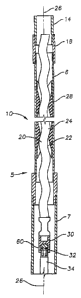
FIGS. IA and 1B show a conventional progressing cavity (PC) pump assembly.
While the preferred embodiment of the invention described herein relates to PC
pump
assemblies, the invention is not limited to use in PC pump assemblies only,
and may be used in
other ESP assemblies as well. In FIGS. 1A and IB, the pump assembly has a pump
assembly
housing 5 consisting of a tubular pump housing 6, a flex shaft housing 7, and
an intalce housing
8. FIG. 1A shows an upper pump assembly section 10. FIG. 1B shows a lower pump
assembly
section 11 and an electric motor assembly 12. Referring to FIG. 1A, a string
of production
tubing 14 extends from a wellhead at ground surface (not sliown) into a well.
Tubular pump
housing 6 is located at the lower end of production tubing 14. Pump housing 6
is connected to
production tubing 14 with a threaded collar 18.
Within pump housing 6 is a metal rotor 20 with an exterior helical
configuration.
Rotor 20 has undulations with small diameter portions 22 and large diameter
portions 24, which
give rotor 20 a curved profile relative to axis 26. Rotor 20 orbitally rotates
within an elastomeric
stator 28 which is located in pump housing 6. Stator 28 has double or multiple
helical cavities
located along axis 26 through which rotor 20 orbits.
A rotor coupling 30 attached to the lower end of rotor 20 has a rotor
receptacle 32
that receives the upper end of a metal flexible shaft 34. During normal
clockwise rotor
operation, gravity and the reaction force due to rotor 20 pumping fluid upward
will keep rotor
receptacle 32 engaged around the upper end of flexible shaft 34. Flexible
shaft 34 flexes off of
axis 26 at its upper end to allow rotor 20 to orbitally rotate.
~.M , ...........,... :..; , w. ~ ~.R_ a.....~.~ . _,..,,. _~.,
,_....,.~~.,..n...... ~..,..~.~, ,.
CA 02457596 2004-02-13
Referring now to FIG. 1 B, the lower end of flexiblle shaft 34 is received by
a splined
receptacle 36 on the upper end of a drive shaft extension 38. Drive shaft 40
extends upward
from the top portion of seal section 42 and engages drive shaft extension 38
at drive shaft
extension bottom receptacle 45. Drive shaft extension 38 is supported by
bearings to keep it
radially constrained. Drive shaft extension 38 is located within intake
housing 8. The upper end
of intake housing 8 is mounted to the lower end of flex shaft housing 7. The
lower end of intake
housing 8 connects to seal section 42.
The drive shaft 40 is powered by electric motor assembly 12, which is located
in a
motor assembly housing 41 releasably secured to the lower end of intake
housing 8. Motor
assembly 12 includes seal section 42 mounted to a gear reduction unit 48. Gear
reduction unit 48
is mounted to an electric motor 50. An electrical power cable 52 connects to
electric motor 50
and extends up alongside the pump assembly to the ground surface (not shown)
for receiving
electrical power. Seal section 42 seals well fluid from the interior of
electric motor 50 and also
equalizes the pressure differential between the lubricant in motor 50 and the
pump assembly
exterior.
FIGS. 2A and 2B show engaged coupling assemblies for shaft elements within the
pump assembly. FIG. 2A shows the upper end of flexible shaft 34 engaged with
rotor receptacle
32 attached to the lower end of rotor 20. FIG. 2B shows the lower end of
flexible shaft 34
engaged with drive shaft extension top receptacle 36 attached to the upper end
of drive shaft
extension 38.
Referring now to FIG 2A, rotor receptacle 32 has a bore therewithin with
longitudinal
internal splines 54 extending downward that are complimentary in size and
shape to interfit with
6
CA 02457596 2004-02-13
the longitudinal external splines 56 of the upper end of flexible shaft 34.
Rotor receptacle 32 and
flexible shaft 34 have been axially aligned with one another and moved toward
engagement. The
splined upper end of flexible shaft 34 is inserted into rotor receptacle 32.
As a result, the
longitudinal external splines 56 at the end of flexible shaft 34 become
engaged with the
complementary longitudinal internal splines 54 within rotor receptacle 32 to
transmit torque.
Referring now to FIG. 2B, drive shaft extension top receptacle 36 has a bore
with
longitudinal internal splines extending upward that are complimentary in size
and shape to
interfit with the longitudinal external splines of the lower end of flexible
shaft 34. Drive shaft
extension top receptacle 36 and flexible shaft 34 have been axially aligned
with one another and
moved toward engagement. The splined lower end of flexible shaft 34 is
inserted into drive shaft
extension top receptacle 36. As a result, the longitudinal external splines at
the end of flexible shaft 34 become engaged with the complementary
longitudinal internal splines within drive shaft
extension top receptacle 36 to transmit torque.
Drive shaft extension bottom receptacle 45 has a bore with longitudinal
internal
splines extending downward that are complimentary in size and shape to
interfit with the
longitudinal external splines of the upper end of drive shaft 40. Drive shaft
extension bottom
receptacle 45 and drive shaft 40 have been axially aligned with one another
and moved toward
engagement. The splined upper end of drive shaft 40 is inserted into drive
shaft extension
bottom receptacle 45. As a result, the longitudinal external splines at the
end of drive shaft 40
become engaged with the complementary longitudinal internal splines within
drive shaft
extension bottom receptacle 45 to transmit torque.
7
CA 02457596 2004-02-13
Referring to FIG. 3, rotor 20 is secured by threads 66 to rotor coupling 30.
Fastener
apertures 58 are positioned such that a fastener 60 can be closely inserted
into each fastener
aperture 58 and disposed through the walls of rotor receptacle 32 to be
secured to.the portion of
flexible shaft 34 within rotor receptacle 32, thus securely interconnecting
flexible shaft 34 to
rotor receptacle 32. Referring to FIG. 4, fastener 60 preferably comprises a
key 62 and a screw
64. A mating recess 68 is formed on the end of flexible shaft 34 for alignment
with fastener
aperture 58. Key 62 extends through fastener aperture 58 into recess 68. Key
62 is a cylindrical
member with a cavity 70 for receiving a screw 64. Screw 64 secures in a
threaded hole 72 in the
end of shaft 34. Axial tension between receptacle 32 and flexible shaft 34
transmits through key
62, and not through screw 64.
During initial construction and assembly, some of the adjacent shaft elements
within
the pump assembly may be interconnected and fastened to one another. For
example, rotor 20,
flexible shaft 34, and drive shaft extension 38 may be connected with keys 62,
then inserted into
production tubing 14, pump housing 6, flex shaft housing 7, and intake housing
8 prior to
delivery to the well site. Seal section 42 will normally be connected to
intake housing 8 or flex
shaft housing 7 at the well site. An access port such as hole 74 (FIG. 3) may
be located in some
section of housing, for example, the housing 7 of flexible shaft 34 or the
housing of seal section
42 at the upper end, to allow keys 62 and screws 64 to be installed.
In operation, motor 50 is supplied with power, causing drive shaft 40 to
rotate, which
in turn rotates rotor 20. Thrust is downward as well fluid is pumped upward
through production
tubing 14. If motor 50 is shut off, the weight of the fluid in production
tubing 14 will fall,
causing reverse spinning of rotor 20. Rotor 20 will tend to move upward,
causing tension in the
couplings to occur. The tension is then transmitted through keys 62,
preventing any of the
8
CA 02457596 2004-02-13
couplings from separating. An upthrust bearing in the seal section shaft (not
shown) prevents the
shaft from becoming disengaged with the driver components. The same axial
tension can occur
if motor 50 is powered in reverse rotation.
The invention has significant advantages. By securely interconnecting the
adjacent
shaft elements in the pump assembly, the upthrust forces of the rotor during
counterclockwise
motion are transferred to the seal section shaft and the upthrust bearing
within the seal section.
Thus, the need for a rotor stop is eliminated, which simplifies field use of
ESP systems and
reduces risk of downhole failures.
While the invention has been shown in only one of its forms, it should be
apparent to
those skilled in the art that it is not so limited but is susceptible to
various changes without
departing from the scope of the invention. For example, not all of the
couplings need to be
splined types; rather, some could be secured other ways, such as by threads.
9