Language selection

Search

Patent 2457756 Summary

Third-party information liability

Some of the information on this Web page has been provided by external sources. The Government of Canada is not responsible for the accuracy, reliability or currency of the information supplied by external sources. Users wishing to rely upon this information should consult directly with the source of the information. Content provided by external sources is not subject to official languages, privacy and accessibility requirements.

Claims and Abstract availability

Any discrepancies in the text and image of the Claims and Abstract are due to differing posting times. Text of the Claims and Abstract are posted:

  • At the time the application is open to public inspection;
  • At the time of issue of the patent (grant).
(12) Patent: (11) CA 2457756
(54) English Title: HYPODERMIC INJECTION SYSTEM
(54) French Title: SYSTEME D'INJECTION HYPODERMIQUE
Status: Expired
Bibliographic Data
(51) International Patent Classification (IPC):
  • A61M 5/30 (2006.01)
  • A61D 1/02 (2006.01)
  • A61M 5/178 (2006.01)
  • A61M 5/24 (2006.01)
(72) Inventors :
  • D'ANTONIO, NICHOLAS F. (United States of America)
  • COLVIN, RICHARD O. (United States of America)
  • D'ANTONIO, LINDA F. (United States of America)
(73) Owners :
  • D'ANTONIO CONSULTANTS INTERNATIONAL, INC. (United States of America)
(71) Applicants :
  • D'ANTONIO CONSULTANTS INTERNATIONAL, INC. (United States of America)
(74) Agent: RIDOUT & MAYBEE LLP
(74) Associate agent:
(45) Issued: 2006-07-11
(86) PCT Filing Date: 2002-08-21
(87) Open to Public Inspection: 2003-02-27
Examination requested: 2004-06-25
Availability of licence: N/A
(25) Language of filing: English

Patent Cooperation Treaty (PCT): Yes
(86) PCT Filing Number: PCT/US2002/026623
(87) International Publication Number: WO2003/015846
(85) National Entry: 2004-02-13

(30) Application Priority Data:
Application No. Country/Territory Date
60/313,978 United States of America 2001-08-21
60/358,861 United States of America 2002-02-22
10/224,034 United States of America 2002-08-20

Abstracts

English Abstract


A hypodennic injection system particularly for use in mass immunizations
having a handpiece with a grasping mechanism for holding ampules filled with
injectate, a plunger for driving into the ampule to discharge the injectate in
an injection process, an injection spring mechanism for driving the plunger, a
motor and/or manual mechanism for cocking the injection spring mechanism, and
an ampule ejection mechanism for ejecting ampules after use under control of a
release mechanism. Ampules can be loaded, used and ejected without contact by
the user of the system or the patient being injected. Also disclosed are a
filling station for filling ampules through their injection orifices, and an
arming device for setting the injection spring. Ampules are disclosed having a
piston which is drivable towards an orifice to discharge injectate through the
orifice. Ampules are also disclosed having enlarged proximal portions for easy
grasping by the grasping mechanism of the injector. Ampules are further
disclosed with separators for mixing lyophilized medication and a diluent.
Further disclosed are magazines for holding ampules for sequential use by the
hypodermic injector. The disclosed system finds particular use as a mass
immunization kit for making numerous injections in the field.


French Abstract

L'invention concerne un système d'injection hypodermique destiné à être utilisé en particulier pour des immunisations de masse, comportant une poignée qui présente un mécanisme de saisie permettant de tenir des ampoules remplies d'un produit d'injection, un plongeur permettant de pénétrer dans l'ampoule afin d'administrer le produit d'injection pendant un procédé d'injection, un mécanisme à ressort d'injection permettant d'entraîner le plongeur, un moteur et/ou un mécanisme manuel permettant de déclencher le mécanisme à ressort d'injection, et un mécanisme d'éjection d'ampoule permettant d'éjecter les ampoules après utilisation, commandé par un mécanisme de libération. Les ampoules peuvent être chargées, utilisées et éjectées sans entrer en contact avec l'utilisateur ni avec le patient qui reçoit l'injection. L'invention concerne également une station de remplissage permettant de remplir les ampoules à travers leurs orifices d'injection, et un dispositif d'armement permettant de mettre en place le ressort d'injection. L'invention concerne également des ampoules présentant un piston pouvant être entraîné vers un orifice afin d'administrer le produit d'injection à travers l'orifice. L'invention concerne également des ampoules présentant des parties proximales agrandies destinées à être saisies facilement par le mécanisme de saisie de l'injecteur. L'invention concerne également des ampoules présentant des séparateurs permettant de mélanger un médicament lyophilisé et un diluant. L'invention concerne en outre des chargeurs permettant de contenir les ampoules pour une utilisation séquentielle de l'injecteur hypodermique. Le système de l'invention s'avère particulièrement utile en tant que kit d'immunisation de masse permettant de réaliser de nombreuses injections sur le terrain.

Claims

Note: Claims are shown in the official language in which they were submitted.


-38-


What is claimed is:

1. A hypodermic injector for injecting fluid from an ampule loaded in
said injector from a plurality of ampules in sequence, each ampule having a
sealed
condition for containing injectate in a sealed container and an empty
condition
where the injectate was discharged from the ampule without the necessity of
human contact with the ampule before or after injection, said injector
comprising:
a grasping mechanism having a grasping condition for grasping an
ampule without the necessity of human contact and holding the ampule to
receive
an injectate discharge force, and an open condition;
a plunger device movable from a set condition to a discharge
condition for applying discharge force to an ampule in the sealed condition to
release injectate from the ampule to render the ampule in the empty condition;
a first biasing device having a cocked condition for storing a
biasing force in said device and a released condition, said first biasing
device
discharging force to said plunger device to move said plunger device from the
set
condition to the discharge condition in response to the movement of said
biasing
device from the cocked condition to the release condition;
a first cocking mechanism for moving said first biasing device
from the release condition to the cocked condition;
a first biasing device release mechanism actuatable for releasing
said first biasing device from the cocked condition to the released condition
to
effect the movement of said plunger device from the set condition;
an ampule release mechanism for releasing an empty ampule from
said grasping mechanism in the open condition, said ampule release mechanism
including an ampule release member movable from a set condition to a release
condition for engaging and releasing an ampule from said injector, and a
second
biasing device releasable from a cocked condition to a release condition to
drive
said ampule release member to release the ampule; and
a second cocking mechanism for moving said second biasing
device from the released condition to the cocked condition.


-39-


2. A hypodermic injector according to claim 1 wherein said second
cocking mechanism moves said second biasing device to the cocked condition in
response to the loading of an ampule into said injector.

3. A hypodermic injector according to claim 1 wherein said ampule
release mechanism comprises:
a manually operable manual release member for releasing said
second biasing device from the cocked condition.

4. A hypodermic injector according to claim 1 and further including a
motor having a drive shaft operatively connected to said first cocking
mechanism,
said drive shaft being rotatable in one direction to cause said first cocking
mechanism to assume the cocked position from the release position to move said
first biasing device from the release condition to the cocked condition, and
automatically rotatable in a reverse direction to reset said drive shaft for
the next
operation to cause said first cocking mechanism to assume the cocked
condition.

5. A hypodermic injector according to claim 1 wherein said grasping
mechanism assumes the open condition when no ampule is grasped by said
grasping mechanism, and wherein said grasping mechanism includes a disabling
device for disabling said plunger device from moving from the set condition
when
no ampule is in said grasping mechanism and said grasping mechanism is in the
open condition.

6. A hypodermic injector according to claim 1 and further including a
motor having a drive shaft operatively connected to said first cocking
mechanism,
said drive shaft being rotatable to cause said first cocking mechanism to
assume
the cocked position from the release position to move said first biasing
device
from the release condition to the cocked condition.

7. A hypodermic injector according to claim 6 wherein said
hypodermic injector further includes a handpiece with a housing for containing
said grasping mechanism, plunger device, first biasing device, first cocking
mechanism, biasing device release mechanism, ampule release mechanism and
second cocking mechanism, wherein said motor is remote from said handpiece,
and wherein said injector further includes a coupling mechanism for
operatively
coupling said motor to said first cocking mechanism.


-40-


8. A hypodermic injector according to claim 6 wherein said
hypodermic injector further includes a handpiece with a housing for containing
said grasping mechanism, plunger device, first biasing device, first cocking
mechanism, biasing device release mechanism, ampule release mechanism,
second cocking mechanism and motor.

9. A hypodermic injector according to claim 1 wherein said grasping
mechanism comprises:
gripper jaws having a closed position for releasably engaging an
ampule inserted in said grasping mechanism and an open position;
a jaw expansion spring device having a set position for biasing said
gripper jaws to the open position and a release position;
a jaw capture sleeve having a holding position for releasably
holding said gripper jaws in the closed position and a release position for
enabling
said gripper jaws to move to the open position;
a jaw capture sleeve return spring releasable from a set position to
a release position for biasing said jaw capture sleeve from the release
position to
the holding position when in the set position;
an ampule eject spring releasable from a set position to a release
position to eject an ampule from said hypodermic injector; and
an ampule release mechanism for moving said jaw capture sleeve
from the holding position to the release position and for releasing said
ampule
eject spring from the set position to the release position;
said jaw capture sleeve being movable from the release position to
the holding position, said jaw expansion spring being movable from the release
position to the set position, said jaw capture sleeve return spring being
movable
from the release position to the set position, and said ampule eject spring
being
movable from the release position to the set position, in response to the
loading of
an ampule into said gripper jaws.

10. A hypodermic injector according to claim 1 wherein the ampules
have an outer wall with an interior chamber for containing the injectate, a
proximal end and a distal end with an orifice in the distal end through which
injectate can flow, the chamber extending between the distal end and the
proximal
end, and a piston movable from the proximal end towards the distal end to
force


-41-


injectate from the chamber through the orifice, wherein said injector further
includes a motor having a drive shaft operatively connected to said first
cocking
mechanism, said drive shaft being rotatable in one direction to cause said
first
cocking mechanism to assume the cocked position from the release position, and
said motor shaft being operatively connectable to the ampules and being
rotatable
in the reverse direction to draw the piston from the distal end of the ampule
to the
proximal end of the ampule to enable filling of the ampule with the injectate
through the orifice.

11. A hypodermic injector according to claim 1 and further including a
magazine for sequentially presenting an ampule to be grasped by the grasping
mechanism from ampules held in sequence in a strip of ampules, said magazine
comprising:
a housing having a holding region for holding a strip of ampules, a
presenting region for making an ampule accessible to said grasping mechanism
and walls for guiding a strip of ampules from said holding region in sequence
to
said presenting region;
a take-up spool for taking up portions of the ampule strip after
ampules have been withdrawn from the strip by said grasping mechanism; and
a driving device for moving said take-up spool to receive the
portions of the ampule strip after ampules have been withdrawn from the strip.

12. A hypodermic injector according to claim 11 wherein said housing
comprises:
an access wall having access surfaces defining an opening to said
presenting region wherein said grasping mechanism can grasp an ampule in said
presenting region and withdraw the ampule from said magazine.

13. A hypodermic injector according to claim 11 wherein said walls
define a curved, generally helical path for the ampule strip, wherein the
ampule
strip following the outermost part of said path locates the lead ampule in
said
presenting region to be grasped by said grasping mechanism, prior to the
disposition of the ampule strip having had the ampule withdrawn therefrom on
said take-up spool.

14. A hypodermic injector according to claim 13 wherein said
magazine comprises:


-42-


a base portion having said walls extending therefrom, said walls
further defining a compartment for holding said take-up spool; and
a cover portion having a funnel-shaped opening to said presenting
area from which an ampule on the ampule strip extends from said presenting
region to be grasped by said grasping mechanism.

15. A hypodermic injector according to claim 11 wherein said driving
device is a negator spring.

16. A hypodermic injector according to claim 11 wherein said walls
define at least one linear path in said housing for guiding the ampule strip
towards
said take-up spool, and wherein said presenting region is on said linear path
adjacent to said take-up spool.

17. A hypodermic injector according to claim 16 wherein said walls
define at least two parallel linear paths connected by a path interconnecting
an
adjacent end of said paths, wherein the ampule strip is movable along one
linear
path in one direction and along the adjacent path in the opposite direction,
said
linear paths terminating at said presenting region adjacent said take-up
spool.

18. A hypodermic injector according to claim 17 wherein said housing
comprises:
a base portion from which said walls extend, said base portion
further having a take-up spool compartment for holding said take-up spool; and
a cover for said base portion, said cover having a funnel-shaped
opening for receiving a portion of an ampule in said presenting region to
provide
access to said grasping mechanism to grasp the ampule.

19. A hypodermic injector according to claim 11 wherein said housing
comprises an exterior wall having an opening to said presenting region for
said
grasping mechanism to grasp an ampule in said presenting region, and further
comprising guiding walls for guiding said grasping mechanism to said opening
to
grasp an ampule.

20. A hypodermic injector according to claim 1 wherein said first
biasing device is at least one spring having a biasing force sufficient to
drive said
plunger device with enough energy to eject injectate at jet velocity.

21. A hypodermic injector according to claim 20 wherein said at least
one spring has a spring force of at least 60 pounds.


-43-

22. A hypodermic injector according to claim 21 wherein said at least
one spring has a spring force of at least 80 pounds.

23. A hypodermic injector according to claim 21 wherein said at least
one spring has a spring force of between 60 and 105 pounds.

24. A hypodermic injector system for making injections at a field site,
said system comprising:
a hypodermic injector for making injections, said hypodermic
injector comprising:
a grasping apparatus having a closed position for holding
ampules containing injectate for subsequent discharge of injectate during an
injection, and an open position for terminating the holding of an ampule;
a plunger for being driven into a held ampule to discharge
injectate from the ampule;
an injection spring having a set condition and a released
condition operatively connected to said plunger, said injection spring driving
said
plunger into the ampule when said injection spring is released from the set
condition;
a spring cocking member for being movable from a rest
position to a setting position for moving said spring from the released
condition to
the set condition;
a coupling for coupling an external energy source to said
spring cocking member to move said member from the rest position to the
setting
position;
a trigger operatively connected to said injection spring for
releasing said injection spring from the set condition to the released
condition to
render an injection;
an ampule ejection device for ejecting an ampule from said
injector;
an ampule eject spring operatively connected to said ampule
ejection device and having a set condition and a released condition, said
ampule eject
spring effecting the discharge of an ampules from said grasping apparatus when
said
grasping apparatus is in the open position upon the release of said ampule
eject
spring from the set condition to the released condition, the leading of an
ampule into


-44-
said grasping apparatus effecting the changing of said ampule eject spring
from the
released condition to the set condition; and
an ampule release mechanism for placing said grasping
apparatus in the open position and for releasing said ampule eject spring from
the set
condition to cause said ampule ejection device to eject an ampule from said
injector;
and
a motor and battery module being selectively connected to said
coupling for resetting said cocking member from the rest position to the
setting
position.
25. A hypodermic injection system according to claim 24 wherein said
injection spring has sufficient spring force in the set condition to drive
said plunger
with enough force to eject injectate from the ampule at jet speed.
26. A hypodermic injection system according to claim 24 wherein the
spring force of said injection spring is at least 60 pounds.
27. A hypodermic injection system according to claim 26 wherein the
spring force of said injection spring is at least 80 pounds.
28. A hypodermic injection system according to claim 27 wherein the
spring force of said injection spring is between 80 and 105 pounds.
29. A hypodermic injection system according to claim 24 and further
including a motor module selectively connected to said coupling for resetting
said
cocking member from the rest position to the setting position, and a battery
selectively coupled to said motor to energize the motor.
30. A hypodermic injection system according to claim 24 and further
including a manual reload module for selectively connecting said reload module
to
said coupling for manually resetting said cocking member from the rest
position to
the setting position.
31. A hypodermic injector for discharging injectate from ampules in
sequence in an injection process, said injector comprising:
an ampule grasping mechanism for grasping an ampule prior to an
injection;
a plunger for being driven into the ampule to discharge injectate from
the ampule;


-45-
an injection spring releasable from a set position to drive said plunger
into the ampule;
a ball screw assembly having a motor with a motor shaft, said motor
shaft being selectively rotatable in forward and reverse directions, and a
ball screw;
a power linkage operatively connected to said ball screw assembly
and to said injection spring, said power linkage having a cocked position for
releasing said injection spring from the set position, and a release position;
a firing trigger actuable for releasing said power linkage from the
cocked position to the release position;
an ampule release system including an ampule release trigger, and an
ampule release member for ejecting an ampule in response to actuation of said
ampule release trigger;
a motor coupler mechanism connectable and disconnectable from
said motor to stop operation of said motor;
a first switch being releasable to stop operation of said motor and
being actuable to cause said motor to rotate in the forward direction to reset
said
power linkage from the release position to the set position and to put said
injection
spring in the set position;
a second switch actuable in response to the actuation of said ampule
release trigger; and
a switch arm being movable in one direction in response to actuation
of said firing trigger to release said first switch to stop operation of said
motor, and
said switch arm being movable in a reverse direction in response to actuation
of said
ampule release trigger to actuate said first and second switches to reset said
power
linkage and set said injection spring and to cause said motor to reverse
direction, said
ball screw moving in response to the reverse direction of said motor to
disconnect
said motor coupler mechanism from said motor to stop said motor.
32. A hypodermic injector for discharging injectate from ampules in
sequence in an injection process, said injector comprising:
a handpiece;
an ampule grasping mechanism for grasping an ampule prior to an
injection;


-46-
a plunger for being driven into the ampule to discharge injectate from
the ampule;
an injection spring releasable from a set position to drive said plunger
into the ampule;
a ball screw assembly having a motor with a motor shaft, said motor
shaft being selectively rotatable in forward and reverse directions, and a
ball screw;
a power linkage operatively connected to said ball screw assembly
and to said injection spring, said power linkage having a cocked position for
releasing said injection spring from the set position, and a release position;
a firing trigger actuable for releasing said power linkage from the
cocked position to the release position;
a switch being releasable to stop operation of said motor and being
actuable to cause said motor to rotate in the forward direction to reset said
power
linkage from the release position to the set position and to put said
injection spring in
the set position; and
a switch arm being movable in one direction in response to actuation
of said firing trigger to release said switch to stop operation of said motor,
and said
switch arm thereafter being movable in a reverse direction to reset said ball
screw
assembly.
33. A hypodermic injector for injecting fluid from an injection
chamber having an exit nozzle in a sequential manner, each injection occurring
from the chamber without the necessity of human contact with the exit nozzle,
the
injection chamber or the injecting fluid, said injector comprising:
a plunger device movable from a set condition to a discharge
condition for applying discharge force to the injection chamber to eject
injectate
fluid from the chamber; and
a motor having a drive shaft operatively connected to said plunger
device to move said plunger device from the set condition to the discharge
condition, and for moving said plunger device from the discharge condition to
the
set condition.
34. A hypodermic injector according to claim 33 and further including
a perforator operatively connected to the chamber for injecting fluid
injectate in
response to the movement of said plunger from the set condition to the
discharge


-47-
condition, said motor rotating said drive shaft in an increasing manner during
an
injection process, to increase the discharge force applied by said plunger to
increase the pressure in the injectate fluid to increase the depth of
injection in a
body being injected as compared to the depth of injection by an injector
having a
diminishing discharge force.
35. A hypodermic injector for injecting fluid injectate from a supply
having a housing for holding the injectate fluid, the supply being finable
from a
reservoir, said injector comprising:
holding apparatus for holding the supply of fluid injectate and for
receiving an injectate force to discharge fluid injectate from the supply;
a plunger operatively connectable to the supply, said plunger being
movable from a set condition to a discharge condition for applying discharge
force
to the supply held by said holding apparatus to discharge fluid injectate from
the
supply, and said plunger being movable from the discharge condition to the set
condition to effect the transfer of injectate fluid from the reservoir to the
supply,
in preparation for the next injection by said hypodermic injector; and
a motor having a drive shaft operatively connected to said plunger,
said motor rotating said drive shaft in one direction to move said plunger
from the
set condition to the discharge condition and rotating said drive shaft in the
opposite direction to move said plunger from the discharge condition to the
set
condition.
36. A hypodermic injector according to claim 1 wherein said ampule
release mechanism comprises:
a second biasing device releasing member for releasing said second
biasing device from the cocked position.
37. A hypodermic injector according to claim 36 wherein said second
biasing device releasing member comprises:
an automatically operable release member for releasing said second
biasing device from the cocked position in response to an immediately previous
injection.
38. A hypodermic injector according to claim 1 and further including a
magazine for sequentially presenting an ampule to be grasped by the grasping


-48-
mechanisms from ampules held in sequence in a strip of ampules, said magazine
comprising:
a housing having a holding region for holding a strip of ampules, a
presenting region for making an ampule accessible to said grasping mechanism
and walls for guiding a strip of ampules from said holding region in sequence
to
said presenting region.
39. A hypodermic injector according to claim 38 wherein said walls
define a curved, generally helical path for the ampule strip, wherein the
ampule
strip following the outermost part of said path locates the lead ampule in
said
presenting region to be grasped by said grasping mechanism, prior to the
disposition of the ampule strip having had the ampule withdrawn therefrom.
40. A hypodermic injector according to claim 13 wherein said
magazine comprises:
a base portion having said walls extending therefrom; and
a cover portion having a funnel-shaped opening to said presenting
area from which an ampule on the ampule strip extends from said presenting
region to be grasped by said grasping mechanism.
41. The combination of a hypodermic injector and at least one ampule,
said hypodermic injector being actuable for injecting fluid from said at least
one
ampule loaded in said injector from a plurality of ampules in sequence, each
ampule having a sealed condition for containing injectate in a sealed
container and
an empty condition where the injectate was discharged from the ampule without
the necessity of human contact with the ampule either before or after an
injection,
said injector comprising:
a grasping mechanism having a grasping condition for grasping
said at least one ampule and holding the ampule to receive an injectate
discharge
force, and an open condition;
a plunger device movable from a set condition to a discharge
condition for applying discharge force to the ampule in the sealed condition
to
eject injectate from the ampule to render the ampule in the empty condition;
a first biasing device having a cocked condition for storing a
biasing force in said device and a released condition, said first biasing
device
discharging force to said plunger device to move said plunger device from the
set


-49-
condition to the discharge condition in response to the movement of said
biasing
device from the cocked condition to the release condition;
a first cocking mechanism for moving said first biasing device
from the release condition to the cocked condition;
a first biasing device release mechanism actuatable for releasing
said first biasing device from the cocked condition to the released condition
to
effect the movement of said plunger device from the set condition;
an ampule release mechanism for releasing an empty ampule from
said grasping mechanism in the open condition, said ampule release mechanism
including a release member movable from a set condition to a released
condition
for engaging and releasing the ampule from said injector, and a second biasing
device releasable from a cocked condition to a release condition to drive said
release member to release the ampule; and
a second cocking mechanism for moving said second biasing
device from the release condition to the cocked condition.
42. The combination of a hypodermic injector and at least one ampule,
said hypodermic injector being actuable for injecting fluid from said at least
one
ampule loaded in said injector from a plurality of ampules in sequence, said
at
least one ampule being one of individually packaged and multiple ampules in a
magazine, each ampule having a sealed condition for containing injectate in a
sealed container and an empty condition where the injectate was discharged
from
the ampule without the necessity of human contact with the ampule either
before
or after an injection, said injector comprising:
a grasping mechanism having a grasping condition for grasping
said at least one ampule and holding the ampule to receive an injectate
discharge
force, and an open condition;
a plunger device movable from a set condition to a discharge
condition for applying discharge force to the ampule in the sealed condition
to
eject injectate from the ampule to render the ampule in the empty condition;
a first biasing device having a cocked condition for storing a
biasing force in said device and a released condition, said first biasing
device
discharging force to said plunger device to move said plunger device from the
set


-50-


condition to the discharge condition in response to the movement of said
biasing
device from the cocked condition to the release condition;
a first cocking mechanism for moving said first biasing device
from the release condition to the cocked condition;
a release mechanism actuatable for releasing said first biasing
device from the cocked condition to the released condition to effect the
movement
of said plunger device from the set condition;
an ejector mechanism for ejecting an ampule in the empty
condition from said grasping mechanism in the open condition, said ejector
mechanism including an ampule release mechanism movable from a set condition
to an eject condition for engaging and ejecting an ampule from said injector,
and a
second biasing device releasable from a cocked condition to a released
condition
to drive said ejector mechanism to eject the ampule; and
a second cocking mechanism for moving said second biasing
device from the released condition to the cocked condition.

43. A combination according to claim 41 or 42 and further including a
magazine for presenting an ampule to be grasped by the grasping mechanism,
said
magazine comprising:
a housing having a region for holding ampules, at least one segment within
the region for making an ampule accessible to said grasping mechanism and
walls
for allowing the ampules to be extracted from said holding region in sequence
fur
use in said injector.

44. A combination according to claim 41 or 42 and further including a
container for holding said members, and retractable legs for converting said
container into a table.

45. A combination according to claim 44 and further including panels
attachable to said container for providing a work surface.

Description

Note: Descriptions are shown in the official language in which they were submitted.


CA 02457756 2005-09-08
HYPODERMIC INJECTION SYSTEM
't
Backsround of the Invention
Field of the Invention
This invention relates to hypodermic injection systems, and in particular to
those residing in a kit format. It more particularly relates to hypodermic
injection
l0 systems in kit form for mass inoculations, using electrical or manual
power.. The
invention additionally relates to hypodermic injection systems having ampules
that are
processed to avoid cross contamination.
Descriution of the Prior Art
Many forms of hypodermic injection systems are available. These systems
15 include rapid delivery of vaccineshnedications with jet injectors that
utilize the same
orifice for every injection, and in some cases, use individual, single use
ampules that
must be handled by the vaccinator when filling them with vaccine and/or when
inserted or removed from the injector. Soiree are manually armed, these to
include all
personal use inj ectors now available, and some have otb~er means of power
such as
2o compressed gas. None of the injection systems are available in kit form
that will
provide healthcare workers with everything. needed to deliver thousands of
shots in
remote or urban locations before returning to a central location for an
equipment re-
supply or re-energizing the power sources, and none supply single use, self
destruct
ampules in . a magazine format that can also be used as a shipping container,
or if
25 needed, as a mixing structure for the simultaneous preparation of numexous
lyophilized filled ampules.
Elements of this disclosure that were considered in earlier patents by at
least
one of the present inventors are: (1) one ampule per injection found in U.S.
Patent
5,080,648, (2) the magazine concept for .holding ampules while connected to
the
30 injectox, and a guard ring around the ampule to discourage splashing are
found in U.S.
. Patent 5,318,522, (3) inserting new ampules andlor discarding used amlaules
without
the need of any physical ~ contact by the user, and ~ also the arming station
for

l ,. , I ~~ , , l , I
CA 02457756 2005-02-02
-2-
compressing an energy storage spring in the hand piece are found in PCT
application
Serial No. PCT/CZS00/07470, and (4) perforator (or mini-needle) delivery for
reduced
pressure and pain to the patient is found in U.S. Patent 6,056,716. One of the
present
inventors has a pending patent application directed to a structural
containment of low
cost syringes used at high pressure. Elements from each of the four patents
are
discussed in the present disclosure for mass immunization systems, clinical
injectors,
and personal use injectors, and the invention herein will represent
improvements or
new ways for performing these vital functions for all types of injection
systems.
1o The invention in its preferred form provides the equipment needed for an
electrically powered injection kit, including enough battery power for
thousands of
injections without nieans of support required from a central location or
conventional
sources of power. The basic means of energizing the inj ector is electrical
power;
however, as a user option, the kit and injection devices preferably also
include a means
for manual operation to assure continuation of the ,injection procedure if the
transportable power sources are depleted and/or a source of renewable power is
not
available. The risk of cross-infection is avoided with disposable, single use,
pelf
destruct ampules (also referred to as cartridges, capsules, vials, etc.) that
are designed
to interface with the injector in such a way that user.contact with the
ampules both
2o before and after the injection is unnecessary. In addition, with respect to
the preferred
embodiment, the trigger is disabled until the amgule is securely held in place
with the
combination of a grasping jaw assembly and a locking sleeve to prevent the
possibility
of an ampule becoming a projectile when the injection ram is released. The
ampules
can be pre-filled by the manufacturer with liquid or lyophilized medication,
or can be
2s filled on site if necessary. Also included in the kit are magazines that
hold numerous
ampules before re-supply is needed. These magazines are designed for rapid,
sterile
delivery when used with the injector. In some cases, the magazine also serves
as the
shipping container for the ampules, and has the capability of simultaneous, on
site
mixing of the lyophilized filled ampules when needed. Alternatively, a filling
station
30 provides an efficient and sterile means for filling the ampules with liquid
or
lyophilized medication just prior to delivery.
The method for non-contact changing of ampules has utility for clinical


CA 02457756 2004-02-14 !
! ~:!, ,~"," "ii", .,, I,I ii aC;i, ~i"~~i ir~:!: . :;:;I! n ;!,." ;:;:!f
'".;:~! ." irv!' "!~ i~",~= °";I~ ii,;.!! (i'.~i; il...~E ~~;:J~
~!...:: !! ..' ..... ......1 ...... ....... .. !!. ... ~:..:!t ~!:::!! !;.....
....... ... ....... ... ._.. ._.. , .. _ _ ._....
s i v L. n'~ 8
_>-
situations and personal use injections as well, where avoiding the risk of
cross !
infection to healthcare workers is critically important when dealing with
patients
=~'~~oring dangerous pathogens. By the same token, where the risk of cross
infection
is not a factor, such as patients receiving insulin, or perhaps the daily
delivery of
growth or other hormone injections, the patient or healthcare worker assisting
them
can easily handle the ampule for both insertion and removal with the novel
grasping
system disclosed. The availability of this system has special utility for
people who
find the prior art techniques for filling the ampule and manually arming
personal-use
injectors to be physically challenging, if not impossible, in some cases.
to For all of,the injection scenarios discussed, very short perforators (1 to
2 mm) ,
as the exit nozzle, and ~used for piercing the injection site prior to jet
delivery, are
included in the preferred embodiment because they allow for low pressure
injections '
(200 to 1,000 psi) as opposed to typical jet injection pressures on the order
of 2,000 to
3,500 psi or more. Properly contained ampules, as discussed in the pending
U.S. .
patent application referred to .above, open the door for manufacturer-modified
insulin
and other syringes having 27 or 28 gauge needles that are already produced by
the
hundreds of millions, which when supplied at perforator length will provide an
' _ injection orifice on the order of .008 or .007 inches, which are typical
diameters for jet .
injection systems. The economy of this approach is quite substantial
Summary of the Invention
The object of this invention is to provide a new, high-speed injection system
that is economical, technically suited to campaigns for mass immunization and
meets
the needs of reliability, ergonomics, power availability, cost, safety and
eiiecnve
injections. The system is designed with several options for both powered and
manual
operation so that the needs of a wide variety of users can be met, these to
include
clinical and personal use injection systems. One option for powering the
injector is an
embodiment wherein a motor is remote from the handpiece discussed below, and
referred to as a "Motor-Off Tool" (MOT) "Handpiece" with three methods
including
both electrical and manual means for compressing the inj ection spring. Also
available
3.o is another embodiment ~~-herein a motor is included in the handpiece, and
referred to as
a "Motor-In-Tool" (IVIT) "Handpiece" similar to that reported in earlier
disclosures by
at least one of the inventors; however, according to a preferred embodiment in
this


CA 02457756 2004-02-14
~I.~~li ~...;, ...~~~.. ; . i~ ~~ ... i,.~.~~ .,~ It ~ ...,.p i ~": i ...,
..,.~~~ ."~~~~ :~.,~1~ ,. I ~ ~"~~ .,.";i :.,..~e v,"In u." ~ .""p
t. II",;, .. .. II"~~ ,.::I! 1(...:I Ii_... . ... I~ :.. ;L::1.( il::;ls
ii'::.. ,.:::I! :: ~i.:_. _ II_ ~~.. ~! .:::It II:::.. II~ il .....Ii ..:::(~
-4-
disclosure, rather than a rotating cam mechanism for compressing the energy
storage
spring, a gear reduction and ball screw are used to do the same thing which
provides
novel methods and advantages for operating the motor in both the forward and
reverse
directions. For example, motor reversal allows for increasing the speed of
rapid,
repetitive inj ections by compressing the inj ection spring iu one direction
and then
reversing direction for an immediate return to the starting point in
preparation for the
next arming cycle regardless of whether or not the present injection is
delivered. An
internal switching arrangement determines when the motor drive reaches the
intended
location, then provides an appropriate signal to first stop, latch the spring,
and then
l0 , reverse motor direction at the appropriate time. This sequence of
repeated motor
reversal takes place for every injection cycle, the distance of travel in each
direction
being determined by the volume of injectate to be delivered. In every case
described,
the mass immunization kit will also include a means for manual delivery if
necessary;
and this system has utility as a manual device for clinical situations.
~ . In an alternate embodiment, the forward direction of the motor allows for
the
ball screw drive to completely eliminate the energy storage injection spring
by using a
direct drive delivery from the motor to the ampule piston. One of the
advantages of
direct drive is the ability to provide an ever-increasing drive voltage to the
motor that,
in turn, will yield a prof 1e of increasing pressure over the course of an inj
ection. This
increasing pressure will drive the injectate ever deeper, rather than ever
more shallow,
-' which will discourage the inclination of medication being left on the
surface as is
sometime seen with the usual spring driven, orifice oriented systems. This
feature is
especially useful forr personal use injectors used by diabetics who are often
very
sensitive to the correct amount of insulin entering the body. Availability of
reversing
motor direction can also be used for filling an empty ampule, and has
particular utility
with personal use inj ectors as an improvement to the tedious manual methods
now in
use. To do this, the injector ram will first grab the plunger of an empty in-
dwelling
ampule, and then, v~rith a push button command by the user, the inj ector will
pull the
plunger back to draw vaccine from a supply connected to the front end of the
ampule.
Mechanical or magnetic means can be used to make this connection to the ampule
piston. Once the ampule is full by virtue of the reverse direction, a low
speed button
controlled motor drive v~.ll allots= the vaccinator to slowly "j og" the
piston fox~x~ard,


i CA 02457756 2004-02-14
1 a,~l~ !I~,~, ", I". ,,. I i1, 1 ~"" i ",I ,.,.yi ..".yl .,."I! ,. I II t .".
! "",y! y .., ! t1 .", !
!1..w'.: .. i~.a~ '~..I( I~...i~ Ir;;.~~ " ~ _...:[ !1~~.y( jjM~yt i~.._
..::~~! .~ li~... ._~~. il,..t~ :~~.~! tl'~,.. if...~l II~,~E ,..~y
_.. 1 r,
and visually determine when all air is expelled from the ampule. For direct
drive
delivery, the motor is then transferred to its high-speed mode to drive the
injectate into
the inj ection site.
The ampules are designed for interfacing with a circular set of grasping jaws
on
the front of the injector. In one embodiment, the system comprises the
following: (1)
the ampules are packaged on a tear-away paper strip, (2) a filling station
fills the
ampules with pre-mixed, liquid vaccine while attached to the strip, (3) two
different
magazine options are available that house the ampules for rapid, easy
insertion into the
magazine, and then, one by one into the inj ector, (4) the inj ection is
followed by self
to destruction of used ampules, (5) two different handpiece options (the
choice
v
depending on user circumstances), and (6) several options for compressing the
spring.
The high-speed manual option mentioned earlier is an especially important
feature for
financially strapped countries that .are unable to afford higher-level
injection systems.
The primary means for arming the automatic injector is electrical power for
energizing
a motor that serves to compress an injection spring. It should be noted that
the spring-
energized inj ector options are virtually always adaptable ~to manual
operation as either
a primary or , emergency back-up system. -This option is not available with
conventional compressed gas, COa or ignitable gas drive systems.
Also disclosed are means for an on site mixing of pre-filled individual
ampules
2o having lyophilized medication in one compartment, and its mixing diluent in
a
---~' companion compartment, the two being separated by an appropriate
barrier. Several
means axe shown for utilizing a barrier between the medication and its
diluent. The
barrier can be frangible or a one-way valve. In one embodiment, a filling
station will
provide sufficient force for filling the individual ampules with pre-mixed
liquid
- 25 vaccine through the exit nozzle, an option that is also useful for the
personal use
injectors described above. This approach for front end filling will virtually
eliminate
the problem of having air enter the chamber that usually occurs when filling,
ampules
by creating a vacuum when drawing back on the plunger. Alternatively, the
filling
station can provide sufficient force to insert the diluent through the exit
nozzle and
3o then mix it ~zth lyophilized medication located in the ampule.
A new concept of a mixing magazine allows for simultaneous, on-site mixing
of an entire magazine full of the pre-filled, lyophilized/diluent cartridges.
In this case,
.., 3


1 CA 02457756 2004-02-14
I::.tl .,.. ..:j:: ,.:'i II II;"11 ii.,:fl II",II .r~ II'..If tl;.,~ ni'..,
.,..It :,... ~,~..i! ~:I' ~'~..i; :.:u'1 ::~;II':..f~ Ii~:.t' ";::fit
I~",~ ~~...:: .. .. ..... ..... .!..:. ....... . .. ... If-f! !C.".:!
!l:::.:..'.:ai ;:: ?:_... ._!... ....... ._...! f._.» .4,__ .._... ......1
G
the magazine can also be used as the shipping container from the manufacturer
to
anywhere in the world thus, of course, lowering cost and fm-ther reducing the
risk of
contamination due to intermediate handling.
In summary, the system includes a transportable injection station or kit that
is
s easily moved from place to place by foot, bicycle, motor scooter,
motorcycle, water,
air transport or whatever means is available for moving people and equipment
to an
immunization site. If no other working surface is conveniently available at
the site,
legs provided as part of the station are opened and extended to the proper
height for
.the user, and optional flat panels from one to all of the four sides of the
housing are
l0 extended to form a working surface if needed. . When the kit is opened, the
healthcare
- worker will have everything needed for thousands of inj ections without any
other
means of support for the amount of time expected at the location. As mentioned
above, the kit will include magazines of the selected type, filling station if
needed,
enough battery power to provide the number of shots expected, and a module for
15 manually arming the injector in the event that all battery power is
unexpectedly
depleted, andlor the power needed for recharging the batteries is not
available.
Brief Description of the Drawings
Figure 1 is a pictorial view of a portable injection system or kit according
to
- the invention; -.
20 Figure 2 is a partially exploded, pictorial ~riew of one embodiment of the
--~' invention having a motor off the tool;
Figure 3 is a pictorial view of a mechanical arming system for use with the
embodiment shown in Figure 2;
Figure 4 is a pictorial view of an electrical or optionally manual arming
station
25 for compressing an injection spring in the embodiment shown in Figure~2;
Figure Sa is a pictorial view of a Motor-In-Tool injector having a removable
motor and battery module for arming the Motor-In-Tool embodiment of the
invention;
Figure 5b is a pictorial view of a motor-In-Tool injector having a removable
motor module for the Motor-In-Tool embodiment of the invention;
30 Figure ~c ~is a pictorial view of a removable, back-up manual-arming module
for the Motor-In-Tool embodiment of the invention;
Figure 6a sho~-s a permanent Motor-In-Tool injector according to the


CA 02457756 2004-02-14
u.",~ n.,:" .";i.,. " , ~' ", ,' °;::~ ,. r ""." ",.,i, .",.,. ..n
,".~, "",, ,;; i ~".,~ ~'.,.i, "..,
.~ !...1~ ~'~:;~t It..,ll'.1....... " ~~:.;~~ II~~~j 7~~I,i ;I,:::....;,:[! a
~:::...,.:~.. ~~.It ....'»S 1~..:,. ~~.It if.,it ,p~y
i
_ ~ _ ~~~~~';Jj
invention, in pictorial form;
Figure 6b is a cut-away view of the Motor-In-Tool injector illustrated in
Figure
6a, showing its internal mechanism;
Figure 7a .is a cut-away view of a second injector for the embodiment of the
Motor-In-Tool invention depicted in Figure.6a, showing its internal mechanism
in its
armed condition;
Figure 7b is a partly cut-away front view of the injector shown in Figure 7a
also showing the internal mechanism in its armed condition;
Figure 7c is a cut-away side view of the injector shown in Figure 7a showing
to its internal mechanism in its fired or unarmed condition.
Figure 7d is a cut-away front view of the injector shown in Figure 7c showing
"~ its internal mechanism in its fired or unarmed condition.
Figure 8a is a cut-away view of a version of an injector for the first
embodiment of the invention for the Motor-Off Tool injector shown in Figure 2
with
an ampule .illustrated with a perforator at the exit port; -
Figure 8b is an enlargement of the ball transfer subsystem shown in Figure 8a
~ w
Figure 8c is an enlargement of the jaw structure for grasping ampules as
'shown
in Figure 8a;
Figure 8d is an illustration of one embodiment for self destruction of a
2o perforator aftex use in Figure 8a;
--- Figure 9 is a pictorial view of a used ampule being ej ected from the j aw
structure shown in Figure 8c;
Figure 10a is a pictorial view of ari unused, empty ampule according to an
embodiment of the invention;
' Figure lOb is a pictorial view of the ampule shown in Figure IOa filled and
ready to deliver an inj ection;
Figure lOc is a pictorial view of the ampule shown in Figure IOa in the
disabled state after an injection has been given;
Figure 11a is a perspective view of an alternate embodiment of a frangible
piston for use in the ampule showil in Figures 10a-1 Oc;
Figure-1 Ib is an end ~~iew of the piston show in Figure 11 a;
Figural lc is a view taken along the line A-A in Figure 1 1b;
,, _ .. .. . . _ , .. .
r .. . . _. _ ~, ~:.... ~ . , :_.:..


i CA 02457756 2004-02-14 t
n",,~ a"," ; ". ," a i q;;, ' ";~~ ; .,,::p ~ :::' ~ i ",:,i~ ...;at ~ , ",i,
.""i, : , !; , ,!"," "...a
..:..° ~!...:, ''!I. ,: ~:...I~ .~:ii Il.::il !!..... .. " .! , .I ,t
Ii:::;; ,;~ ~' ":::!~ ::: !!_... .'.:!1.. !1..!! .:.a a::~~ :~-1! !,_:!
°:!:
_g_
Figure 12a is a pictorial view of a portion of the invention showing ampules
attached to a cardboard/paper strip;
Figure 12b is an enlargement of a portion of Figure I2a;
Figure 13a is_ a pictorial view of the ampule strip shoi~m in Figure 12a when
inserted in an unfolded magazine;
Figure I3b is an enlargement of a portion of Figure 13a showing a close-up
view of posts for securing ampule strips to a folding magazine; .
Figure I3c is a pictorial view of the apparatus shown in Figure 13a with a set
of magazine wings being folded over the center segment;
lo ~ Figure 13d is a pictorial view of the apparatus of Figure 13a in a fully-
folded
magazine ready for injection;
'~ , Figure 14a is a pictorial view of another embodiment of an aspect of the
invention showing an ampule strip coiled up and placed in a rotating auto-feed
magazine; ,
Figure 14b is a pictorial view of the embodiment shown in Figure 14a with a
cover placed on the rotating auto-feed ,magazine shown in Figure 14a and ready
fox
use;
Figure l4c.is a pictorial view of a negator spring used in the magazine shown
in Figures 14a-14b, 16, .17 and I 8a-18c.
2o Figures 14d and 14e are schematic drawings of a pawl and ratchet device
used.
.- in the magazine shown in Figures 14a, 14b, 16, 17 and 18a-18c.
Figure 15 is a pictorial view of ampules according to the invention located in
a
tray or crate assembly;
Figure 16 is a pictorial view of the second embodiment of the invention shown
in Figure' 2 retrieving a filled ampule from a rotating auto-feed magazine as
shown in
Figures 14a and 14b;
Figure 17 is a pictorial vied of anofiher embodiment of the magazine portion
of
the invention showing a linear auto-feed magazine with an open cover;
Figure 18a is a pictorial view of another embodiment of the magazine .aspect
of
the invention showing a rotatable auto-feed magazine v~ith an improved
structure for
ampule retrieval;
Figures 18b and 18c are ~>7.ev,Ts of the magazine sho~~~n. in Figure 18a in
i<vo
y a
.,, a a

CA 02457756 2004-02-14
':;;n ° . ".~!.., .. ,.~ ..... ,~..,:! .....!~ , .. .. ,., .,...!,
..,.," . i ..u a : ,.,.,i, ."." ~: : r ".,,
i~ I~.,... !: ..~ ~ ~.= ~;~!~ ,.._: !e::.. .. ~~ !!::::: ~f:::!~ ll~::,~
!.::.: .:::1. ::: !!::: ~ '. ~,."~~ ,..,. a~,; . Mil°4 ~I !I ~.!!
.:::~,
' ,, ~~'';';; JJ~~CI ~hc~
-9-
mounting modes.
Figure 19 is a pictorial view of a filling station according to the invention
in
partially exploded form;
Figure 20a is a schematic view of an ampule according to the invention with a
lyophilized/diluent vaccine separated by a mixing piston with a one-way valve;
Figure 20b is a schematic view of the ampule shown in Fi~ure 20a with
internal lyophilized vaccine. and external mixing diluent being forced into
the exit
nozzle;
Figure 20c is a schematic view of an ampule according to the invention with
to lyophilized vaccine, having an external appendage containing the mixing
diluent;
Figure 20d is a schematic view of the ampule shown in Figure 20c having an
-' external appendage containing both lyophilized vaccine and diluent
,separated by a
barrier;
Figure 20e is a schematic view of another aspect of the invention showing a
magazine full of ampules, each with a collapsible storage unit; and
Figure 20f is a schematic view of another variation of an ampule according to
the-3nv~ntion showing i~ with lyophilized vaccine and diluent separated by a
slidable
frangible barrier.
Detailed Description of the Preferred Embodiments
2o Figure 1 illustrates a customized, all-inclusive, carrying case 12 for the
portable
injection system, station or kit 10 according to an embodiment of the
invention. Each.
_ carrying case 12 of the portable system 10 contains all components necessary
for a
healthcare team to efficiently administer thousands of inj ections at the rate
of up to~ 600
. people per hour, this equipment to include several magazines, at least one
handpiece,
enough battery power for the number of injections expected, manual arming
means if
needed, at least one filling system, several battery charging options and
simple tools to
effect repairs to the system components. . .
The case has retractable legs (not shown.) for standing the unit in an upright
position and flat panels from the four sides that can be pulled out to form a
working
3o surface (not shown) for the healthcare team if no other surfaces are
available or
convenient. Sterile components such as gauze, cotton balls, band-aids, etc.,
will also be
housed in the case. Several ampule strips should be included in the case as a
fill-in or


CA 02457756 2004-02-14 I
1';;a~ ,~w~" ..~.., , ' ii Ii 'C::;~ ~ ~.,li ,;::!! r ;°;,:p ,r...
~!".; .,.,.!, ...,.i, .,W~ ~I' "i! ~~'.,li ,~;?, ~~:::1! sr~,!,_ 1~,.i,..",.,
:l ...,.. .. .. ....: ..... I.... v...... ... " ,r~ ~a ,.,° ; )!:::.:
.....,. _. .1..... ....'.. ..,..,~ y"1 ~...4 ,....u .~::~~
(~ ;J '.,_.:
- 10-
backup in case a delay occurs in the normal procedure for delivery; however,
for the
enormous number of inoculations needed for a mass immunization campaign, it is
anticipated that the required number of ampules will be tr~~- ~ -orted to the
site in separate
cartons and/or shipping magazines, and might even contain pre-filled liquid or
lyophilized ampules.
One of the main embodiments of the invention is referred to as a "Motor-Off=
Tool" or "MOT," where the electrically operated motor (discussed below) is
separable
from the injection device that it is driving. The injection device preferably
includes a
handpiece for effecting inj ections.
1 o Figures 2 through 4 are illustrations of the various ways to deal with
arming a
~ Motor-Off Tool (MOT) device, i.e., it includes a handpiece 14 containing an
injection
spring (discussed below) and a trigger 16, but a motor 1 S and a battery 17 on
motor-
battery belt assembly 18 are located off of handpiece 14. Because of this, MOT
handpiece 14 is less expensive and extremely light at an estimated weight of
approximately 8.5 ounces (240 g), where the handpiece is made from an
appropriate
plastic, and the plastic and inj ection spring comprising nearly all of the
weight of the
handpiece. The reduced weight has the added advantage of less fatigue to the
healthcare
worker when thousands of injections are given.
Figure 2 shows a Motor-Off Tool apparatus 100 having a belt-motor assembly
located on a belt pack 22, arm pack or the~like, and is attachable to a
convenient location
-.-~ on the healthcare worker giving the injections. A moveable center (not
visible but
similar to a speedometer cable) located inside tether or cable 26 is fastened
on one end to
a draw rod (discussed below) on handpiece 14, and is used for applying the
pulling 'force
needed to compress an injection spring in handpiece 14, also discussed below.
The
outside shell of tether 26 is connected to handpiece 14 with a coupler
mechanism 24.
The other end of the movable center of cable 26 is attached to a motor drive
19 located
on belt back 22, and~this end of tether or cable 26 is attached to the housing
of motor
drive 19 u>ith a coupler or connection mechanism 28. After an injection is
given, a
signal goes back frorn~the handpiece to the motor control which will instruct
the motor to
pull on the movable center of cable 26 to again compress the spring in
preparation for the
nexrt injection as explained later, The injection fluid or injectate is held
in disposable
ampules 2 l.. This option allours the vaccinator to move around freely and
proZrides for
. ..-y


CA 02457756 2004-02-14
~;;'u II°,." i ." ., a i ~ .":. ,.,: , .""~~ . .""y ..:. ,~.,;,, ,., yl
.,u ."~, :""r~ ".,.~, ,i,.~;~ ; I ,...,,r
I~ . ..... °n .: .. o, ~.,.I, ; ~. ,.... « ~~,... ,~,.." ;,.... ;,~:1~
::°:~' :: :~..... ...~~.. ~(_ t.. .. ~I~ I~:.. ,~_... 1::;i ..:::~,
.. .. v .... .... .__.I_._....~ .... _.. .... . .
n'1'4
r
~~; i,'~.
- 11- ~ ~ :~u a ~:~
very.high-speed operation, all the while requiring very little outside
assistance.
Mechanical tether 26 should be of adequate strength, and could be fairly stiff
which, for
~r ,.e situations will also possibly add unwieldy weight to handpiece 14.
Figure 3 illustrates a manually operated foot pedal assembly 30 for activating
the
movable center of mechanical tether 32 which functions exactly as described
for tether
26 in F baure 2 for compressing the spring in handpiece 14. The outer shell of
tether 32 is
connectable to handpiece 14 with coupler mechanism 34. No additional energy.
is
needed and no motor is involved for using this foot-operated device.
Figure 4 shows a pair of Motor-Off Tool (MOT) injectors residing in rearming
station 40; however, in this case an electrically operated arming station 42
is used.
- While not mandatory, the primary obj ective of arnzing station 42 is for the
vaccinator and
an assistant to work together, wherein the vaccinator will give the shots and
the assistant
will move the handpieces around as described below. Arriling station 42 has a
pick-up
cradle 44 for holding a fully armed Motor-Off Tool injector, and a rearming
dock or port
location 50 to accept an unaizned injector. _A_rmin_g station 42 can be
adapted to hold
more than one MOT handpieee, wherein two are shown in Figure 4 as configured
for use
with an assistant. Cradle 44 on arming station 42 is for holding an injector
14 that has
already been armed and ready for use. A pick-up cradle adjustment knob 46 on
arming
station 42 is adjustable in order to place the handpiece at an angle that is
most convenient
2o and comfortable to provide access to a fully armed injector 14 for the
vaccinator.
Arming station 42 also has an arnzing station base 48 on which the
aforementioned pick-
up cradle 44 and a rearming dock or cradle 50 is located. In addition, base 48
also has an
. optional or back-up manual arming lever 52 to rearm the handpiece resting in
aoclc or
cradle 50 in the event electrical power is not available, all of which are
discussed below.
At the beginning of an immunization sequence, both injectors are typically
unarmed.
When arming cradle 50 senses the presence of handpiece 14, it pulls the
injector draw
rod to compress the injection spring to the latched position, as discussed
hereinafter.
After arming is completed, the armed handpiece is moved to pick-up cradle 44,
and the
second injector is placed in arming cradle 50 and armed. At this point, the
vaccinator
takes an armed injector from cradle 44 to give an injection and the assistant
v~ri.ll move
the second injector to pick-up cradle 44 while at the same time the vaccinator
will
squeeze trigger 16 of handpiece 14 to then release the injection spring,
therein driving a
.. . . _. a . .., _ W, ~. : . _..~


CA 02457756 2004-02-14
i~~ ~!i ~~"", ".ii", ,, .~~ !~ i~ w ".,, ~ ",i, ",..i~ , . ,t..., ~::;!t
'";:~~ "..n, :,u a".'~ ",.,,1 ~ ;( ~~~,nl I~"?~ "."n
....: ..,.. '...!( i1 II !!~~. '1'~:I! 11~;,!1 1,~'.,~I !s--. _...!! n::
!!.'w. ..~!.. !I ,I ...'~i «':_t ...~ .!~ ..::an
..... .._. _ ....... ~ ZA',4~'A~~y',1.-.:
-12-
ram in handpiece I4 to expel the jet velocity fluid from the ampule. After
giving an
injection, the vaccinator ejects used ampule 2I and deposits handpiece 14 into
the now
empty rearming cradle or dock ~0, and picks up the armed handpiece 14 from
cradle 44
wherein handpiece I4 is ready to retrieve a new ampule 21 for the next
injection.
Benefits with arming station 40 include the elimination of any kind of tether,
so that the
vaccinator's arm has complete freedom of movement. Also, in a campaign with an
adequate supply of assisting personnel, which is often the case in mass
campaigns,
arnling station 40 will relieve the vaccinator from all duties except for
delivering
injections, thus insuring an efficient, high-speed operation. If, however, a
vaccinator is
1 o working with very little assistance, the arming station 40 option would
require more
motion and effort on the part of the vaccinator than the mechanical tether
option. Also,
'~ . unlike the mechanical tether option, in which the vaccinator can move
around freely, this
option requires the vaccinator to remain close to the arming station in order
to swap
handpieces 14 after each injection. The arming station concept is also
conveniently
applied to the personal use inj ector, wherein the motor and battery can be
housed in a
. unit that also serves as a compact storage and carrying case that is easily
concealed by
the user, and which also makes the handpiece very compact, lightweight and
easily
maneuvered for a personal injection.
A second main embodiment of the invention is referred to as a "Motor-In-Tool"
or "MIT," where an electric motor is plugged into or otherwise is a part of
the injection
.- device which it is driving, in this case a handpiece as described below.
Referring to
Figures Sa-5c, they show together a Motor-In-Tool device or apparatus 200
having a
handpiece 1.14, and in the embodiment of F bwxe 5b, a battery-belt assembly 11
~ having
a battery 120, and a motor module with a motor 119.
Fiwres Sa-Sc illustrate, various options for arming the Motor-In-Tool (MfT)
injector or handpiece I14. Depending on the required shot capacity, battery
I20 can be
housed on handpiece I14 or in a separate off tool compartment as shown in
Figure Sb.
Just like the Motor-Off Tool (MOT) handpiece 14, the MIT handpiece l I4 houses
an
inj ection spring, : the force transfer system, trigger, and the ampule
grip/reJ.ease system as
discussed belo~T.
F ~aure 5a illustrates a removable module 130 containing a geared down motor
I32. Depending on the desired injection pressure and stroke length for a
particular


t. CA 02457756 2004-02-14 i
.'' I iI'C;' i("~il u;;:i! .~" ~:.,",!t n::' n";° i::;:u ..;;, ...
a~:!!"i ~r"I~ ~~,;:j~ n~,U II':'I~ ~I.",~ ',',;ji
(. .: ' ~ !I , ~ ! n .r u~ tc : . ~ ~ ~ ~ ,
- 1 j - , .- -~ ~ . .,
injector desi~, any number of conversion values could be used, one value
implemented
for this system has an armature speed as high as 13,900 revolutions per minute
(R.PM),
but with very Iow torque. This high armature speed is reduced by 29:1 with an
appropriate gear reduction to yield an output speed of 480 FPM to shaft 136 (8
revolutions per second), and except for an inevitable loss due to conversion
efficiency,
the torque output is therefore increased by the same ratio, thus providing the
power
needed to compress the injection spring (not shown in this figure). In this
embodiment, a
battery 134 is connected to the motor inside of module 130, wherein both the
motor and
battery are connected to the handpiece 114 during its operation by insertion
of an output
1 o shaft 13 6 into a mating receptacle 13 8 on handpiece 114.
. Figure Sb illustrates a~ removable module that contains only the geared down
motor 119 when the motor is connected to handpiece 114, but battery I 18 is
off the tool
during operation and is connected to motor 119 with an electrical tether 140.
Motor 1 I9
has the same type motor, shaft 136 as shown in Figure Sa for insertion into
receptacle
138. . This is a more likely situation for providing power to handpiece l I4
when
thousands of injections are expected,, i.e., a larger remote battery pack can
be clipped
. onto a belt or vest, carried in a pocket, or placed on a stationary surface
next to the
~ vaccinator without the risk of excessive fatigue from constantly moving the
greater
weight. The MIT handpiece 1I4 (that is, when motor I19 is connected thereto)
is
estimated to weigh about 14 ounces and is somewhat larger than an MOT
handpiece 1 I4
~~ (when motor 119 is not connected); however, it is still much lighter than
any other mass
campaign injector known to the inventors. The MIT handpiece I14 weighs about
14.5 to~
16.5 ounces, wherein added to the 8.5-ounce MOT handpiece I 14 are motor I 19
at about
4 ounces and the linkage from the motor to the gears weighing from 2 to 4
ounces. The
option shown in Figure Sb provides the vaccinator full range of, arm motion
and
complete freedom to walk around; that is, handpiece 114 does not have to be
put down
between injec-dons and one-handed operation to load, inject, and eject ampules
21 is
possible. V~rhile not shown, it is clear than other sources of power, such as
solar or main
power, v,=hen converted to the voltage needed can also be used to drive the
motors in
Fi~~ure ~b. .
Fiwre Sc sho~~~s a module 142 for the manual awning of handpiece 114, and
~xrhich is connected to the injector in the same manner as that described for
the modules
.. . . .. _..-,


CA 02457756 2004-02-14
:,..i~ ~!.,.~. :.,~',., ,,., ii ~~ a!:;"y :!.,.~ ;;;;U ; ;~"!mr." ~!..,. ~~:It
."..t, ",;tt t ."t, "..," ,...t~ ., j ! .",no
..... :: .. !...~ ....:.t !:...~~ :!..._ .. . ..: !!::'!! !!:.".;_ !!.__
..:':!: ;. !i.- _a1. ~t ;; _~:!: lo:.: ~~....~! ~1..~,1~ .~'o
~~~~~i~~~~
~a .
~ ~,,
-14-
of Figure Sa and Sb. This format takes the place of the motor and the battery
pack
needed to energize it. Module 142 has a housing I44, and a manually driven
handle 148
coupled to geared down interface prior to moving output shaft 146 which is
connected to
receptacle 13 8 on handpiece 1 I4 during its operation. Manual arming of
handpiece 114
is facilitated by rotating handle 148 several times to provoke the amount of
rotation
needed on output shaft 146 to compress the injection spring. While not shown
in any of
the figures, the MIT injector 200 can also be manually rearmed by compressing
the
spring from the front end when the injector nose is inserted into a
corresponding manual
rearming station.
l0 Figures 6a and 6b show one version of a complete MIT injector 114', and
Figure
6b is a cut-away view of the motor location and the other significant
components. In this
'" case, motor 119' receives power from electrical tether 140 as illustrated
in Figure Sb, but
in this case, motor 119' is a permanent future on injector 114'. This figure
also includes
an ariipule grip/release system, force transfer system, trigger, and the
injection spring, all
which are also incorporated in the MOT design 100. Ampule 21 is not installed
iri
handpiece 114' in these figures. ~.
z
With reference to Figure 6a, handpiece 114' has a housing I50 with a trigger
116'. Turning to Figure .6b, an inj ection spring 152 is shown in the
compressed state and
is held in compression between a ball screw nut 154 and an injection release
sleeve 156
having a shoulder 158 against which spring I52 rests, wherein, motor 119'
rotates ball
__.-~ screw nut 154 in the spring compression direction until it reaches and
actuates a motor
stop switch which is more fully e~.plained with the embodiment of Figure 7.
Optionally,
,the spring can be made to latch in this position and the motor is instructed
to
immediately return ball screw nut 154 to the lower portion of screw 164.
Alternatively,
ball screw 154 can stay in the position shown until the injection is given and
the used
ampule released from the handpiece, at which time, the'motor ~x~ill reverse
the ball screw
position as described to be reset to again compress spring 152. Both
techniques have .
been implemented, the advantage of immediate reversal is sacking time in
preparation fox
the ne~~t inj ection. A force transfer system 160 transfers force from inj
ection spring 162
to system 160 and ultimately to a ram for driving a piston inside an ampule.
Motor 119'
is mounted in housing 150 and has a drive shaft I6I for rotating a spur gear
163, uThich
,in turn rotates a spur gear 162 to rotate a ball screw I64 uFhich moves ball
screw nut 164


CA 02457756 2004-02-14
n;;i, ,,I..,.. ,.,~',., ,., i! iI !l::;i~ r"~I ~i:;U ,. '":;! s!:;' :r,.,
,:,::!t '";?: '";;p .at !! i ~ ~., ,."!t i~,.,'! ~i",i; ,.;;y
!!' i1...:: .. :: ....! ...... ~:...:. ....... ., " !!::... ~!,yt ~!:::!f !!__
...,.!~ ::: !!..... ..it '~"~~ v.'s: !!;."..: ...._i s._... .......
.. .t._.. ..
~'i''.i~' ~ ~_ . ,q,
~Y t;:mj ~~~ as''~
'
to compress injection spring 152. No thrust bearing is required for protecting
drive shaft
I61 because the Ioad is decoupled from the motor and the gearbox by virtue of
the offset
nature of the spur gears. An electric tether connector port I66 is shown as a
connection
for connecting a battery or, as suggested for the Figure 5 embodiments,
connecting other
sources of electrical power to motor 119'.
Force transfer system 160 includes a casing I68' for holding an ampule plunger
rod, a transfer mechanism held in casing 168, and a ramrod extending from
injection
release sleeve 156 to effect the aetive operation of the transfer mechanism.
The ampules
are held in handpiece 114' by gripper jaws 172, the operation of which is
discussed in
l0 further detail for Figure 8c below. The foregoing mechanism included in
handpiece
- , 114', with the exception of motor I 19' installed in handpiece 114', is
essentially the same
"~~' as for the MOT handpiece 14.
When trigger I6, 1 I6 or 116' is squeezed on any of handpiece 14, 114, 114',
the
stored energy in injection spring 152 exerts the appropriate force on.transfer
system 160
(more fully described below for Figure 8a), which then applies injection
pressure to an
ampule ramrod (discussed below). After an injection, art ampule release button
170 is
compressed and the ampule capture sleeve (discussed below) is pulled back from
its
locked position. The gripper jaws 172 expands, are held open, and the used
ampule 21
either falls out or is pushed away from the front end of handpiece 114'. There
is no need
fox physical contact by the user; however, if desired, ampule 21 can be
inserted and
-.- extracted manually. As described above, at some point in the cycle, motor
119' reverses
its direction to reset handpiece 114'. To install a new ampule 21, the front
end of the
handpiece 114' is placed over the mating back section of a new ampule 21, and
the
capture sleeve is returned to the locked position as soon as gripper jaws 172
are released
and closed. The ampule is now securely held in place for the next injection.
Apparatus
is provided for preventing the actuation of a ramrod for normally injecting
injectate from
an ampule unless gripper jaws 172 are properly holding an ampule because the
actuation
of the ramrod without a properly held ampule could pose a dangerous situation
since the
ramrod could provide a dangerous impact if it were to strike a person.
3o Figures 7a, 7b, '7c and 7d show the internal structure for one embodiment
of the
MIT injector 200. Injector 200 has a handpiece 114" hown in Figures 7a and 7b
in the
armed position, and Figure 7c and 7d, the same in the fired or unarmed
position. lt~T


CA 02457756 2004-02-14
..!1 p~~n ... ~.. ~~~ Ii ~i ?~"~~ ~~~.~Z~ II"?I ~ n ~';::~[ n .... ~L,.~
..'..~I ~~.:.!~ .. li'..~! ~~~~ Ii~..ii ";..1i ~~:.(! ~j~..ii i~..~~' ";
.. I!...:: .. .. ....: .....:. .-.. ,._... ,. I .._ ?~_::a ?aat ?s__.. .__. ._
....._ ".... ...._. ...._. .... . ...
~i ::_. , ''~1
-16-
handpiece I14" includes a housing I50' having a ball screw assembly 172, which
includes a motor and gear train 119", a coupler mechanism 174, a ball screw
I64' and a
ball nut 154'. Coupler mechanism 174 represents a fixed point which locks the
motor in
the housing while at the same time coupling motor 119" and its gear box
(included in the
motor or housing) to ball screw I64'. Member 174 is able to pivot very
slightly (a few
degrees) to allow for movement of ball screw 164' and a power linkage 176 as
ball screw
nut I54' moves up and down on ball screw 164' during the arming process.
Coupler
mechanism 174 also includes a thrust bearing (not detailed in the figure) to
protect the
motor and gear train from the in-line spring load. Power linkage 176,
described in more
to detail below, operatively attaches to ball screw assembly 175 with an
appropriate
. , connector or pivot point 192. The injector spring is included in a rear or
right part of a
-'- spring tube assembly 178. A battery 118' is located within housing 150'
above spring
tube assembly 178. An ampule capture sleeve 180 holds an ampule 21. The
discharge
or removal of a used ampule 2I is accomplished by the sidewise movement of an
ampule
release trigger 182. A ready indicator 184 is located at the rear of headpiece
114" and
extends out the rear end of injector 200 as shown when the injection spring is
compressed. A front view of the unit is shown in Figure 7b.
Power linkage 176 includes a first link 186 connected to ball screw nut 154'
by
connector 192 about which first link 186 can pivot. Link 186 has a free end
188 with a
longitudinal slot 190. A second link 194 is connected to a pin or pivot pin
196 extending
-.. from trigger 116"_ Second link 194 can pivot about pin' 196: A third link
198 is
pivotally mounted on a pivot pin 201 carried on a tube housing 202 which
allows pivot
201 to slide to the left when the injection spring is released, and a fourth
link 204 is
mounted at one end to a pivot pin 206 fixed on handpiece 114", and at its
other end to a
connecting pin 208 extending through slot 190 in first link 186. Link 198 is
coimected to
fourth link 204 by means of the same connecting pin 208 for second link I94.
Pin 208 is
held in place by a retainer 210. '
As mentioned, F bwre 7a shows MIT handpiece I14" in a loaded or armed
position. When trigger I16" is actuated, injection release or second link 1.94
is forced
up~~ardly by trigger 116", therein, connecting pin 208 is raised above the
center point
of links 198 and 204 to unlock these links, and the compression spring in
spring tube
assembly I78 is released and rapidly moves to the left, driving an ampule
plunger rod


CA 02457756 2004-02-14
..", , ,.:,~, . ., ,t ~ n r ....,
I~;;;!e il~:.~. ,:.i~.:: . :' ~~ ~~ !C;.;. l~ ; ... ~i;;:!~ ~;;:;~ ~i:::;~
~~~~!' '°:;;: ,., m..!, ,.~E ;~':,I~ :::!, n~;! r..i~ !i_.!1, :::.'.
.. :...... .. .. ..... ..... ....~ !!..... ..'~ ....... ~~..... ._.... .~...
.__.. ... ....._ ,...... .....
_~~'~,~~~
- I7-
or ramrod into ampule 21 to cause the discharge of the injectate held therein.
Connecting pin 208 moves to the upper end of slot 190 in first link 186, and
then, in
this embodiment (other motions are possible), upon the sidewise actuation of
ampule
release trigger 182, an ampule-ej ect spring engages an ampule ej ector sleeve
which
both withdraws jaw capture sleeve 180 to release jaw expansion springs (not
shown in
this figure) from holding ampule 21 in place in handpiece I14", and a plunger
return
and ampule-eject spring drives an ejector sleeve against ampule 21 to either
eject or to
allow ampule 21 to fall away from the open gripper j aws (discussed in detail
with
respect to Figure 8c). The condition of handpiece 114" after firing, i.e.
after an
injection has been made and just prior to ejection of ampule 21 from the
gripping jaws
- 172, is shown in Figure 7c.
~' Ampule release 182 can also release an ampule in the event no injection is
made.
It also effects release of an ampule if the main system malfunctions.
It is noted that the fully compressed spring in this embodiment latches with a
15, slightly over-center toggle composed of third link 198 and fourth link
204; therefore,
spring release is easily facilitated with a small force to the center point of
this toggle
arrangement when trigger I16" is actuated. Ball nut 154', screw 164' and motor
drive
119", move in both the forward and reverse directions by virtue of electrical
switch
actuation as described below. As described earlier, a ready button 184
extending from
the rear end of housing I5f tells the user when injector 114" is fully armed
for an
inj ection.
After an inj ection has been accomplished and inj ector 200 moves from the
condition in F bwre 7a to that of condition 7c, the direction of rotation of
the shaft of
motor 119" is reversed. Control' of motor 119" is facilitated with the use of
switches
214, 2,16, and 218. When trigger 116" is actuated and toggle 204/198 is
released to
facilitate the inj ection, trigger I 16" also causes a switch arm 2I2 to move
upward with a
guide and stop member 220 riding along a slot 213, thereby releasing switch
216. The
release of switch 216 enables motor 119", but this alone will not permit it to
operate. At
this point, there are t~.vo possible embodiments for having the motox rearm
the injector.
In the first embodiment, when ampule release trigger 182 is actuated and the
used
ampule falls a~c~~ay from the injector, switch 218 is released, and the
combination of
s~ritch 216 and 2I8 enable motor l I9" to rearm the injector 200, at which
time, ball nut


CA 02457756 2004-02-14 t,
~!;;;" ....". ,..Ii", . ,~~ p !I '!::°~ ,...,f ~::::_, . .....,.
,;;::,, .~...;. ;~.::!: °:~;; .. °.:::!. °1I
II°,II ";::I; ;~;~:'! Ii:::L If'r~i :::v_'
!: ~ ~~...:. .. .. ..... :.._.. ,1...!. !:...:: .. " ;~:~.: :!..._ :.._.
....... ..._.. ._ ._.._ ...._. ...... ..._.. .._
-I8-
1 ~4' moves in the downward direction along screw 164". When nut 154" reaches
the
bottom of ball screw I6f, arm 2I2 slides downward wifh guide and stop member
220
riding along slot 213, and switch 216 is again compresseu, while at the same
time, toggle
204/I98 latches to its slightly over center position. Re-compression of switch
2I6 when
ball screw I5f reaches the bottom causes motor 119" to reverse direction and
ball 154'
' immediately returns to the upward part of screw 164 as shown in Figure 7a.
When ball
screw 154' reaches the top, it pulls on shaft 215 which in turn produces a
slight pull on
coupler 174 to pull coupler 174 away from switch 2I4, and the motor stops. In
an
alternative embodiment for rearming the injector, motor 119" reversed
direction as soon
to as the injection is completed. This saves time between shots, however, it
also provides
the risk of dry firing the inj ector if the trigger is pulled before a new,
filled ampule is
'~ inserted into the injector. The choice between the two embodiments is
determined by the
conditions where the injector is to be used. ,
It should be noted that the manual backup, i.e., for situations where
electrical
power is unavailable, could be just as fast as automatic arnzing, but fatigue
to the user
could be much greater due to the physical energy needed at the rapid rate
expected.
Whatever the case, the manual feature is necessary to assure that all inj
ections are
completed at the location before the healfihcare team moves on.
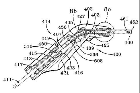
Figures 8a-8c illustrate the details of a complete Motor-Off Tool injector
400;
however, the inner workings, with the exception of how it is armed, apply to
the Motor
--- In-Tool injector as well.
The Figure 8a cut-away shows the off axis energy transfer system consisting of
a
series of balls in a tube and all of the other elements described above. The
off axis
transfer of power was developed in order to provide a handpiece that was less
threatening to children than the gun type structure that has typically been
used. This
model is also easier to handle than the straight-line version (similar in
shape to a
conventional flashlight), provides for a better.distribution of weight, and
helps reduce the
onset of fatigue to the healthcare worker. Several methods were reduced to
practice,
each having its own advantages and disadvantages for certain situations in
mass
immunization.
Refen-ing to Figure 8a, MOT 400 includes a handpiece 414 having a housing 450
with a trigger 416, and a force transfer system 402 ha~~ing an ampule plunger
rod 403,


CA 02457756 2004-02-14 (~
~ :' ~ ... a t "~; s! ; ..,..,. t°:' t,,.,. ""." "",i, . , .. i :! t
..., S .;: ;! t ~ ,1 , ..., ,
If'~,i~ ~i,..:: i"tl'~, ~~ " ~~,~j~ !"::![ t!...!1 11,.... .. ~~ !!'.:.: ~!-.!
a_::!! !!::.. .~::!! ::: !;:.:! ...Ii.. !t...ll .:::~! 11.::. !!...!S ~~'-
..,t~ .:::~
- _
force transfer balls 405 and a ramrod 407. Force transfer balls 405 are held
in and
tangential to the inside surface of curved housing 409. Handpiece 4I4 further
includes a
yaw rod 41 l, a spring tube 413 housing an injection spring 415 and a spring
retainer nut
417. An injection release sleeve 456 includes part of curved housing 409 with
force
transfer balls 405, as well as six release balls 419 which can be transferred
from an
annular channel 421 to an annular pocket 423. Handpiece 414 has an ampule
release
button 425 and leaf springs 427. Ampule release from the front erid jaw
structure is
essentially the same as that described for Figure 8c below.
Figure 8b is a blown-up view of force transfer balls 405 shown in Figure Sa.
l0 Balls 405 are preferably made from steel, and there are "hat" members 429
inserted
between each of the balls that are intended to improve the efficiency of this
transfer by
'-,
helping maintain alignment of the balls to reduce wall friction. Hat members
429 are
preferably made from Delrin. While not shown in,the figures, tube 409 can also
contain
a hydraulic fluid with sealing pistons at either end, rather than balls 405.
The fluid,
along with these pistons, will transfer the power to ampule plunger rod 403
when the
injection spring 415 is released. Tubular transfer. system 402 is the most
compact and
lightest weight of those disclosed; however, its efficiency is not as great as
some of the
others; for example, while somewhat larger, a chain or cable connected to a
pulley and
gear motor combination can also provide the spring compression at higher
efficiency.
2o Selection of a particular transfer system will depend on the energy
available to
accommodate an acceptable efficiency, as well as the premium placed on weight
and size
of the device. ,
Figure 8c is a blown up view of the circular jaw structure shown in Figure 8a.
As pointed out earlier and discussed below, these j aws allow for a no-
personal contact
procedure when grasping and discarding an ampule, and because of that, they
also have
important utility for personal use injectors when used by healthcare workers
for a
particular patient who might be harboring dangerous blood born pathogens, thus
eliminating the risk of cross infection to the worker.
In Fi~-ure 8c, an ampule 21 is held in handpiece 4I4 by three gripper jaws
472.
Ampule 21 has a housing 700 with a cylindrical forward outer surface 702 and a
tapered
. rearward surface 704 that is narrow at its free end and thickens until it
reaches a peak
706 after which it tapers inwardly towards the longitudinal axis of ampule 21
to form a
- .. . ._. .~ .. h~ '
--, .N . .....~ ~ ~


i CA 02457756 2004-02-14 ~~. '
t,.:,~ ,..... .:,",.. ;, a a ~t~~~ ,t..,(, ;~::!! :. ."::!! tt:,".' ~r,..
..,::!i :.".t, ,:..:" "H !,."" ::,.." ..",! ,(",,~ ,(:,.t, ~;::(.
!(..,° ;1...~ ! : ~ ~!,_ !c ..'.; ~t ~.._~ :~..... .. !' ._. s:_ ~!
!!~:!! !!._.. .._!~ ::: !~ ::.: .. ~._ :!._:! ..::'!! !! . , -!! ! ., i! ...,
..
," ..~. _t
-20-
slanting shoulder 708. Gripper jaws 472 each have a head 475 with an inclined
impale
engaging surface 476 for engaging impale shoulder 708. Jaws 472 are biased
outwardly
by jaw expansion springs 478. A jaw capture sleeve 480 engages an abutment 482
on
the outside of head 475 of jaws 472 to hold jaws 472 in a closed position
against the bias
of springs 478. Ramrod 403 follows the longitudinal axis of jaws 472 and
impale 21 (if
installed), and as explained earlier, effects the ejection of serum or other
injectate from
impale 21. A guide and holder 484 has a forward end portion with an inclined
inner .
surface 486 for engaging and holding inclined rearward surface 704 of impale
21, an
inward collar 488 and a rearward cylindrical portion 490. An ejector sleeve
492 extends
l0 partially along ramrod 403, and the inner surface of collar 488 of rearward
portion 490
engages sleeve 492 and holds it against ramrod 403. A plunger return and
impale spring
' 494 extends partially along ramrod 403, including a forward portion between
ejector
sleeve 492 and ramrod 403.
A jaw capture sleeve return spring 496 extends along the inside surface of the
rear part 497 of jaw capture sleeve 480, and has a forward end abutting an
inwardly
extending collar 498 of sleeve 480 and a rear end abutting a gasket 500
extending
between the rearward end of sleeve 480 and the rearward portion 490 of guide
and
holder 484. A retaining ring 502 is located in an annular groove 504 of guide
and holder
484 for maintaining gasket 500 and sleeve and return spring 496 in place.
, Figure 8a shows the MOT injector 400 in its loaded or armed condition, ready
for
..-.- giving an injection. The user actuates trigger 416 by causing it to
pivot on an annular
axle (hidden in this figure but located close to the left end centerline of
plunger rod 403),
which causes a cam 506 on trigger 416 to engage inclined surface 508 to force
injection
release sleeve 456 downwardly along tube 409 containing balls 405. This causes
injection release balls 419 to move from annular channel 421 into annular
pocket 423 in
injection release sleeve 456. Balls 419, which had been restricting the
release of
injection spring 415 in spring tube 413; now permit the release of spring 415.
Therein,
injection spring 415, which at its upper end engages a drive member 510, in
turn drives
draw rod 41 I into ramrod 407 to apply the force from spring 415 into force
transfer balls
405 to move upwardly, the forward ones of which moving around the curve in the
upper
end of tube 409, to drive impale rod 403 into the inner end of impale 2I of
such force as
to cause the ejection of injectate under jet pressure through its discharge
port 710,
_#
t ~.. . . ~. .,-.... .~ .~ ~ . .._.w, 7


CA 02457756 2004-02-14
~ ;;;': :..." ; ~° ~ ;~ !f,:;i' I ,~~~~ ~r;:U : ",~,,. : ~~ ,i"" .,~:!~
":;;~' .., ar;;li ~i~ i~",,~ :~;;~' ~~;;:I! i~..~~ ~~, ,~~ _,~°~~
:( ' ~L..:: ~";~ ° .. .»: ....... . ..... ....... .. ~~ u. ::. ~1:. ~'.
i~: :~~ ~ .... ..»_. ... ..._.. ,..._. .....:. ....... ._..
-21-
It is noted that ampule 21 in this embodiment is shown with an exit port
perforator 460 covered by a collapsible protective front end 462 whose
interior contains
a springy or resilient return material. When front end 462 is pressed against
an inj ection
site, it collapses under the applied force to then expose perforator 460
through the
narrow access hole at the front. The perforator. now enters the very outer
Iayer of the
body and the injecfiion is thereafter delivered. When the injection is
completed,
protective cover 462 re-expands to again, cover perforator 460 thus avoiding
the risk of
injury to the user. Importantly, protective front end 462 is manufactured with
a side-wise
bias that breaks lose when the perforator is first exposed, consequently, when
perforator
460 is drawn back into protective front end 462, the narrow exit hole in 462
will shift to
the side as shown in Figure 8d, therefore making it impossible to again expose
perforator
--- 460. This feature provides protection against any form of after shot
"stick" or reuse by
preventing the perforator from again becoming exposed, and will, in fact,
destroy the
perforator is such front end compression is again. applied.
Thereafter, the actuation of ampule release button 425 withdraws jaw capture
sleeve 480 to the left as shown in Figure 8c, away from forward end 702 of
ampule 21.
This results in jaw expansion spring 478 rotating gripper jaws away from
ampule 21 so
that ampule-engaging surface 476 disengages ampule shoulder 708. Plunger
return and
ampule-ej ect spring 494 urges ej ection sleeve 492 forwardly against the rear
face 712 of
2o ampule 21 to eject ampule 21 from MOT handpiece 414.
Since this embodiment is that of a motor-off tool (MOT) injector, withdrawal
of
ramrod 407 from the forward or fired position must first be facilitated before
a new
ampule can be~inserted into gripper jaws 472. Thus, injector 414 is inserted
into either a
motor driven arming station or a manually'driven arming station to. grab hold
of draw rod
411 and pull on it to recompress spring 415 to the injection ready position. A
new
ampule 21 can now be inserted in the forward end 485 of guide and holder 484,
and jaw
heads 475 will ride along inclined surface 704 of ampule 21 until peak 706
rides over the
. . gripp~g portion of jaw head 475 to releasably lock ampule 21 in place. Jaw
capture
sleeve return spring 496 then moves jaw. capture sleeve 480 to the right as
shown in
F ~wre 8c, to move gripper jauys 472 to the closed position.
MOT handpiece 414 is note- ready for the next injection. The entire system in
this and other embodiments ha~Te been found to make 600 injections per hour,
including
&~~.1...., .r.~~.-1 .-,. D°_ 1'.~~.


CA 02457756 2004-02-14
I..;I' I'"' ~'' i~ I~ iC:;i[ p"~~~ !rv'b ,,., ~;::It n::; a,... "."" ,.;, ~
"":~: . m°: "",i, ",:-n :r°y! :1y ._..~:
II 'L..:: "".~ ~~ . ~ ..... ....... ...... ....... .. ~..... !!.. ~~ ;~ ;~ ! !
.... , .. ..: ?!:_.. w~~.. ?L..II ..:::L, ~!:'.. 1~ " .! ~~cl, "'y
1..._ -.:
-22-
the injection of injectate from each ampule, discarding the ampule and
reloading a new
ampule.
Figure 9 illustrates a full external view of the Figure 7a-7c MIT injector 200
as
seen when ejecting a used ampule 21 into a trash container T without the need
for any
physical contact by the user.
Figures l0a-lOc are three views of one version of a self destruct ampule that
is
conveniently used with this inj ection system.
Figure 10a shows ampule 21 prior to filling. In order to maintain consistency
as
to the location of the proximal and distal ends of the ampule for the
discussions to
to follow, the proximal end is always that end which is closest to the
injector; i.e., the part
of the ampule that is held by the graspzng jaws described earlier. Each ampule
21
w° includes its thin plastic shell or housing 700, cylindrical forward
outer surface 702,
tapered rearward surface 704, peak 706, shoulder 708, an orifice or discharge
port 710
and rear face or proximal end 717. A channel or bore 714 forms a chamber 715
15 ~ extending along the longitudinal ails Of ampule 21, and is open at the
rearward or
proximal end 717 of ampule 21. Orifice 710 is located at the forward or distal
end 716.
An injection piston 718 is located at the distal end 716 while a spool 720 and
a Locking
spring assembly 722 remain at proximal end 717. Piston 718 is made from an
appropriate plastic and has a head portion 724, a body 726 and a base 728.
Spool 720 has
20 a head 730, a body 732 and a base 734. Locking spring 722 is wrapped around
body 732
of spool 720, and has leaf spring members or fingers 736 which are biased
outwardly
from the longitudinal axis of ampule 21 towards the side wall 714 of chamber
715. The
leaf members 736 of the locking spring 722 apply slight outward pressure to
the inner
diameter (117) of bore 714, thus enabling locking spring assembly 722 to
maintain
25 position within bore 714. Herein lies another feature that, in some cases,
would find use
v~rith~a personal use injector. However, it should be noted that in some cases
where
dangerous pathogens are not an issue, some personal use injectors actually
promote. the
reuse of ampules to facilitate greater economy to the user.
Figvire lOb shows a filled ampule. The distal end 716 of ampule 21 is
installed
3o into the filling station (shown in greater detail in Figure 19), and
pressurized injectate is
forced into chamber~714 through the orifice 710, thus driving piston 718
towards spool
assembly 720 at proximal end 717 of ampule 21, ~~-herein it makes ph5=sical
contact with


i CA 02457756 2004-02-14
;y I~"", ..,i,., .~' ii i[ ~i::a~ [j:.~~[ i,°.:,~ "".n ~r,.. ~ ".""
~;:;[~ . ":'~!' ;_°.. [I',~[ ,.:::~s !~_::~''. ?1.~~[ ~~_,~~ .':,~~
.: ..... ...... ...... ~..... .. ' ~ ?'e ::.: ~! :::f [l:::(1 !l:::.: _.....
as !?~~~' !!
s' ,9
.2-1 j -"~ .d
-23-
spool 720 and locking spring 722 and comes to a stop. Due to outward pointing
fingers
736 of locking spring 722, assembly 722 is unable to move any further in the
proximal
direction. The concept of filling through the exit port with the application
of pressure to
the vaccine reservoir offers a substantial advantage by avoiding the insertion
of air into
the injectate chamber during the filling process. This as opposed to the more
common
practice of creating a vacuum in the injectate chamber when the plunger is
pulled back.
While the pulling procedure certainly draws fluid into the injectate chamber,
it also
draws air in at the same time, therein requiring an extra step of carefully
pushing the
plunger forward until all of the air is expelled before giving the shot.
to Figure lOc depicts an ampule 2I after.the injection is completed. Plunger
rod
-. 403 makes contact with end~or base 734 of spool 720, thus driving the spool
720, locking
'- spring assembly 722 and piston 718 forward at high speed to force the high
velocity
inj ectate out through orifice 710 as a coherent j et stream. Once the inj
ection is complete,
piston 718 is firmly lodged in distal end 716 of ampule 21, making reuse
virtually
impossible to further reduce the likelihood of cross infection. .
Figures l la-1 1e depict an alternate embodiment of the piston used in ampule
21
that avoids the use of a locking spring to disable the ampule, but relies
instead on a very
thin frangible section just behind an 0-ring seal on the piston. After the
piston reaches
the end of the inj ection stroke and strikes the distal end of the ampule, the
inj ector ram
continues in the forward direction just far,enough to produce an additional
compression
w, ' . force on the piston which provokes a separation, or breakage, of the
piston at the
frangible ring. Once the piston ~ is broken into two parts, reuse of the
ampule is
impossible. In another form of the same idea, the injector ram fractures a
frangible
center section on the piston. After the piston has fully pushed forward to
complete the
shot, ~ a movable center rod will .continue beyond the end of the ram and
force a hole in
the frangible member; therefore, if a user tries to refill the ampule, the
remains of the
piston cannot be moved to the full position.
Thus, still referring to Figures lla and 11-b, an ampule piston 7~0 is shown..
Piston 7~0 has a head 752, a body 7~3, and an annular groove 754 separated by
a pair of
surfaces 7~6, 7~8 by a distance sufficient to engage in sealing contact an 0-
ring 760. An
elongated, annular groove 762 extends bet«~een a pair of collars 764, 766. A
closed bore
768 (Figure 11c) exrtends from an end 770 of piston 7~0 and ends in a conical
surface
. ~. _..,_~:~
. -'I ..., . . _~..,r>!~n


CA 02457756 2004-02-14
I . .' , ..., :.. , , .. .,.., ..;~i '
't ~~ ~~, 1l . ~ ~ ~~ i~ L"~I I~ i1 !S 1~ ,t.: j~...,i it"p ii' .i! :.~~~ ~
11,' ~~ ,.li~ i~',~~~ _...~s it"~~I 1~~,',il ~~~'~1~ ...~~~1
I . ..... ....... ...... ...... . ... .,.. . ....... ....._
..,... .. . ~ n ' J ' " " n n
~~::~ w;; ~~;e~
-24-
772. The narrow portion 774 between conical surface 772 and surface 758 of
groove
754 forms a frangible web area. As explained above, in use a ram such as
ampule
plunger rod 403 - when activated - is driven into the rear surface 770 of
piston 750 a.s it
moves through its inj ection stroke to ej ect inj ectate from an ampule such
as ampule 21
from chamber 715 through orifice 710. After ampule piston 750 reaches the
bottom of
ampule 21, plunger rod 403 continues its forward motion until its compressive
force
breaks the frangible web area at narrow portion 774, rendering piston 750
useless and
ampule 21 disabled against reuse.
The item shown in Figures 12a and 12b is an example of ampules 21 connected
together on an ampule strip 800 comprising a cardboard and paper combination,
with
''tear-away paper strip 802 looping over each of the ampules as they rest on
cardboard
hacking 804. Ampules 2I are affixed to the cardboard backing when the paper
overlay
802 is secured to the cardboard baclcing 804 by a suitable adhesive 806.
Cardboard
backing 804 extends.beyond distal face 716 of each ampule 21, protecting the
orifice 710
from incidental contact arid possible contamination during handling. A loop
belt 808 is
configured arid serpentined in such a way as to form folds 810 to hold ampules
21
securely inside of each other in the folded over strip during shipping,
handling, and
filling, but allows ampules 21 to be easily torn away when a shear load is
applied by the
handpiece jaws (such as jaws 472) when pulling ampuies 21 out of ampule strip
800, i.e.,
2o a tear-away system. Ampules 21 in Figure 12a and 12b are shown prior to
insertion into
the magazine system (described in more detail below). An alternate embodiment
(not
shown) has the ampules connected together during the molding process, but
insertion
into the magazine and the tear, or breakaway feature is essentially the same.
Each ampule strip 800 preferably contains a number of 0.5m1 ampules 21.
Reconstitution of a 50-dose cake of lyophilized vaccine with 30m1 of diluent
typically
yields 'more than 50 doses of vaccine, especially with the highly efficient
filling station
described below. While a greater number is possible, the number of ampules in
the strip
will be equal to half the average number of doses of vaccine the ,filling
statiori ~~11
extract from the vial (i.e. two ampule strips per vial of vaccine, wherein a
strip will
3o preferably hold between 26-28 ampules). As shown in Figures 12a and 12b,
ampules 2I
are spaced approximately lOmm (0.400") apart, allowing strip 800 to fold in
half
lengthwise (Fiwre 12a), nesting ampules 21 facing one another into the
intervening
~:..,~. , . ..... . :


CA 02457756 2004-02-14
r~n ;:..,. .,.i.., ;. a ~ ~... ,,.,i~ ..;.~! ~. ..,;! :r,., ,i..,, ..."i,
:..",, '~,;:A ~~~~ !! i ",, !i ..;;y ;',..~~ li~,~.~j :.~1,
~!..,~~ ~:::!~ !~., ~! 1!..... .. 1~ !l::.~ v::_~s !!:."?! !!:::.: _:::!: :w
!!_._ ...._. ,:_d~ ..._~ !!: .
~~,~!m~!jf ~~'h:~
-25-
spaces (Figure 12b) for ease of shipping and filling.
The folded strip will be removed from its sterile pouch and interfaced
directly
with the filling station (as discussed below) advancing iteratively to allow
the filling
nozzle to access each ampule 21 and force reconstituted vaccine through its
orifice 710
described above for Figures 10a-1 Oc. The vaccine will push ampule piston'
(such as
piston 718 or 750) back until it stops against a pre-installed spool (such as
spool 720)
and Lock ring (such as locking ring 722), insuring a precise amount of
injectate in each
ampule 21. This spool and lock ring will also prevent the piston from moving
in the
reverse direction once the injection is completed, thus disabling the ampule
and
preventing reuse. Once the ampules 21 are filled, strip 800 is ready to go
into cold ,
storage for use later in the day or to be installed directly into a magazine.
Figures 13a-13d and 14a-14b show two distinct, yet similar, off tool ampule
management systems available with the injection station of Figure l, and the
handpiece
designs described above. By virtue of the ampule strip design in Figures 12a-
12b, a
greater number of ampules are available for the off tool magazines than that
described
for the on-tool magazines of prior art patent IJ.S. Patent No, 5,318,522.
Either of the
magazines can be attached to a working surface, such as the injection system
carry case,
a table, a lanyard around the user's neck, belt pack, arm pack or wrist
mounting, and/or
any other convenient location.
The magazine 820 shown in Figures 13a-13b is a folding magazine. This system
holds a set of ampules 21 in a fixed position relative to one 'another, and
are removed
from any location, one at a time by the handpiece. This system comprises three
plastic
segments: a center segment 822 and two winged sections 824, 826 hinged to each
side.
Segments 822, 824, 826 are initially unfolded, and the open magazine is placed
on a flat
surface, allowing the ampule strip to be laid into the unfolded magazine (F
jwre 13a).
Small posts 828 (Figure 13b) on the inner surface of magazine segments 822,
824, 826
press securely into a set of matching holes 832 in an ampule strip backing
830, properly
locating strip backing 830 on the support walls 834, 836, 838 (F bmare l~c) on
each of
s agents 822, 824, 826, and holding it in place. Additionally, an edge 840 of
backing
830 closest to proximal end 717 of,ampules 21 fits firmly against retaining
rib 708 on the
inside surface of magazine segments 822, 824, 826, keeping strip backing 830
from
sliding while ampules 2I are being extracted one at a time. Ampule strip 800
when
;,, ., n . . . .. , . . _ . ,..,~
.~1:........_. ...__


CA 02457756 2004-02-14 t
.: I I p.~.. ni I ,....h .". ~ ni .. .~~..!I Ic, .._!I il_..~I .._:~~~
~I ~~ .!...:: ~"~I.~, . ~ . 1:...!l ' :: ~~ ,I.~!! t3:::.. _ '' ;r..!. ;,::.,,
i~!, !!..... :~~::~'. ::: i~::! : ~! ':..li 'w::li i4~.'! !.
- 26 -
inserted in magazine 820 includes a loop belt 842 attached to strip backing
830 by an
appropriate means such as an adhesive. Loop belt 842 and backing 830 are
flexible so
that they can bend with the folding of magazine 820. Loop belt 842 has a
sequence of
loops 844 being generally semi-cylindrical for grasping ampules 21 around
ampule body
702 to hold ampules 21 in place. Retaining rib 708 extends across each of
segments 822,
824, 826 for engaging the edge of ampule strip 800 when it is inserted in the
magazine.
Segment 822 has two pairs of opposing hinge arms 848; 849 for cooperating with
hinge
arms 850 on each of segments 824, 826 for forming two pairs of hinges 852.
Hinge arms
850 each have a pin 854 for extending through a hole 856 in hinge arms 848,
849 to
complete respective hinges. 852. Segment 824 has an end plate 858 and segment
826 has
an end plate 860 with a handle 862 attached to it by some appropriate means or
to be
integral therewith. 'Finally, the segments 824, 826 are folded over center
segment 822,
left segment 824 first (Figure 13c). ,The end of right segment 826 snaps fully
over the
opposite ends of the center segment 822 and Ieft segment 824, holding the
system
securely closed . in Its folded position .(Figure 13d).. Snapping occurs by
virtue of
opposing fingers 864 extending from hinge arms 850 into opposing notches 866
in end
plate 860. Strip backing 830 'and loop belt 842 have strategically positioned
pleats or
perforations 868, 870 to allow the folding to occur easily. The folded
magazine 820
(Figure 13d) has a solid bottom surface because of foot flanges 872, 874, 878
on each of
2o segments 822, 824, 826, to protect ampule distal ends 7I 6 and also to
provide a place for
--° . possibly securing magazine 820 to a surface, eifiher through hook-
and-loop strips (e.g.
Velcro) or features which affix to matching surfaces on the inj ection system
carry case.
Folded magazine 820 also has solid sides 880, 882, which allow for gripping.
the
magazine with one hand while extracting the ampules with the handpiece jaws.
The
relative position of the ampules in the magazine allows access to each ampule
in flan.
Proximal ends 717 of fihe remaining ampules provide some guidance to the nose
of the
handpiece, helping the user locate the handpiece nose (such as gripper jaw
heads 475)
appropriately for jaws (such as jaws 472) to grasp the targeted ampule. .After
the last
ampule 21 has been extracted, magazine 820 can be unfolded, ampule strip
backing 830
3o removed and discarded, and a new strip backing 830 of filled ampules 21
installed. The
advantage of folding magazine 820 is simplicit~T. With few,parts and few
manipulations
necessary to operate, this magazine design is likely to be robust and take
minimal time to
,rn, .. " P~- . ... ....~

CA 02457756 2004-02-14
;;:p ~'.,... ."~ ." ; . ~, iI !C::.: ~;~,~~i m~1! ,. ,~;:1! n;;;i~ ;~:;;;:
;!~:1! '",::~; ::: ~r,:;.. ..1~ . i~,..iE .."W!; !c_:I! ii_..« ij_ ii _~";~~
i ....! . ...,_. .., ... .. !~ .... ii_... ....... ....... ._...
'9
27 ~r. ~~P.~:~ '.f ~3 y
load and unload. Protection of the orifice or distal end 7I6 of ampule 21
prevents the
possibility of cross infection, but because proximal ends 717 of ampules 21
are exposed,
some effort must be made by the user to insure cleanliness.
Figures 14a-14b illustrate a rotating auto-feed magazine 890. This system
advances the ampule strip along a track, presenting each ampule at a
consistent location
for extraction. As with folding magazine 820, this system 890 is ideal for
placement on
a table, attached to the injection system case, or ideally, on the opposite
wrist to the hand
used to hold the injector. If desired, auto-feed magazine 890 could also be
worn as a
neck lanyard by the vaccinator. This magazine 890 comprises a load chamber 892
that
l0 holds the ampule strip (such as strip 800 of Figure 12a) and a rotating
take-up spool 898
that collects the empty strip as the ampules are removed, and is similar in
operation to
the film advance system of a camera (Figure 14a). This embodiment includes
four
primary components: a base 894, a cover 896 (Figure 14b), take-up spool 898,
and a
constant-force negator spring 900 (Figure 14c) located and attached to the
inside of spool
898. Spring 900 is shown outside of spool 898 with Figure I4c for clarity.
Housing
base 894 has a bottom wall 902, side walls 904 and interior guide walls 906
for
cooperating with the inside surfaces of side walls 904 to guide strip backing
908 of
ampule strips 909 through load chamber 892. Wall 906 is also appropriately
curved at
wall. section 910 so that load chamber 892 can receive take-up spool 898.
Cover 896 has
a rim 912 that is configured to slip over and slidingly engage the upper
portion of side
walls 904. Take-up spool 898 has a slot 914 for receiving a tab 916 and strip
backing
908, for holding tab 916 as take-up spool 898 rotates to draw ampule strip 800
(or 900 in
Figure 14a) along its path in magazine 890. Ampule strip 909 has ampules 2I
secured to
strip backing 908 by some appropriate means, such as disclosed with reference
to
Figures 13a-13d.
In preparation for inserting ampule strip 909 into magazine 890, the user
pulls
the wind-up cord (not shown, but see F ~°~ure 17 for an equivalent one)
which turns take-
up spool 898 through several revolutions (counterclocltv~~ise in this figure)
to turn spring
900 to the fully wound and latched position. A ratchet-type arrangement having
a pawl
9I8 and a ratchet groove 929 unll prevent the cord from being pulled back into
the
housing by vTound up spring 900 because of the vertical left side on groove
929 and
mating spring loaded pearl 918 on the interior of magazine 890, hot~lever, the
slanted
... ' . . ~,19)
. v ..... . . ~. .a. a.- . ..:w r~ 1 ~ ,


CA 02457756 2004-02-14
I
,." !i i~ !C;;ii I~'.yi ii~;~!t ,. ".,!, ~~~ II,".".:;~ i:;!! ";°;. .,,
ii.::!! ~li_'~...~i ..'.'~i iii;!! li_~4!l fi, il .::
~~...:: ~i .: ..... ....... ...... ....... _ ~~ !:~_. »::'~~ :...._ .......
..._.. ...
_28_ _
surface on the right side of groove 929 will allow spool 898 to rotate in the
counter
clockwise direction during wind-up by having spring loaded member 918 slide
over the
slanted surface during each revolution. To facilitate loading magazine 890,
ampule strip
800 is rolled into a coil and placed in load chamber 892 (Figure 14a). The
user then
threads an extended tail or tab 916 of strip backing 908 along the track or
path as
described above, affixing it to rotatable take-up spool 898. When cover 896 is
placed on
to housing base 894, an appendage on the inside of cover 896 (not shown)
extends
downward to interface with the surface of spring loaded pawl 918 and push it
out of the
way to release take up spool 898. Application of spring tension from constant
force
to spring 900 located in housing base 894 draws strip backing 908 onto spool
898 until an
ampule 21 comes to rest against a stop position defined by wall portion 926.
Cover 896,
which can optionally be attached to the housing base by a hinge on housing
base 894, is
then placed over base 894 to protect the ampules against contamination (Figure
14b). As
stated above, the ratchet is released v;~hen pawl 9I 8 is pushed out of mating
groove 929
in the closing of cover 896. This should be made clear by considering Figures
14d and
14e. In order to cock or set spring 900 prior to the loading of a strip of
ampules, a pull
cord is pulled to rotate spool 898 counterclockwise. As spool 898 is wound
counterclockwise as shown in Figure 14a, spring loaded pawl 918 slides into
groove 929
but does not stop the rotation due to the sliding of the inclined surfaces of
pawl 9I 8 and
groove 929 passing over each other. However, once a strip of ampules is
inserted in load
-- chamber 892, ~ spring 890 would be free to unwind spool 898. This cannot
occur,
however, since while spring qflll ~.rn 1d un~xrind, spool 898 moves a small
amount due to
pawl 918 moving below spool 898 as shown in Figure 14e. Nevertheless, while
pawl '
918 moves into groove 929 as shown in Figure 14d, the ampule strip is locked
in place.
When cover 896 is closed, a bar 897 moves pawl 918 downward so that it cannot
stop
the clockwise rotation of spool 898 as ampules are advanced through magazine
890.
This action-reaction will free spring 900 and advance ampules~21 on baclcing
strip 908 as
described.
A fiumel-like opening 930 in cover 896 proirides access to the ampule 21
resting
3o against the stop defined by wall portion 926. The funnel feature allows the
nose (the
head of the gripping jaws) of the handpiece to be guided easily into position
to grasp the
ampule flange, i.e. the portion near proximal end %~17. Once an ampule 2I is
extracted,
.
. . .._ . . . ....... .


CA 02457756 2004-02-14
i
:,;,i !~a~ ..,1!~,; ;~ n !C.. '"::I! ,: .:;;,p r~,~ ,r.., . ! ,.:..!~ :::"i! !
:r:.u :",, ,~,:1!
,I : .. ..' !1...~~ ,.. ,Ii ~~...~~ !l..... .. ~1 !! ; : ~i~_!t !!_::L :!".. t
..'.::i: a :!:,.. ..a~ . !!..1! .:::~~ !S.:_ '~,»iI ;~.. v -'.-
_29_ . . . .
spring 900 turns spool 898 and automatically brings the next ampule 21 into
position at
access opening 930. After the last ampule 21 has been extracted, cover 896 is
removed
so that ampule strip 909 can be removed and discarded. A new ampule strip 909
is then
installed as described above. Position of the pull-cord at all times is an
indicator of the
number of ampules remaining in magazine 890 as the cord is stepwise pulled
into the
housing when ampules 21 are extracted. Auto-feed magazine 890 makes use of the
handpiece easier, because the ampule access point (opening 930) is always at
the same
place and the fiu~nel in the cover (e.g. conical) can guide the jaws into
position. To
allow for the unlikely case of magazine malfunction, a slot 932 in housing
side wall 904
provides a manual feed option where the user can pull the strip ~to advance
the next
ampule 2I into position for retrieval by the handpiece.
Figure 15 illustrates the ampules housed in a crate assembly rather than the
magazine structure described above. Accordingly, a crate 940 is provided which
is made
of cardboard, plastic or other appropriate material, which has a series of
orifices 942
i5 defining the entrance to receptacles 944 for receiving distal ends 716 of
ampules 21 with
proximal ends 717 extending from receptacles 944 for engagement by jaws Of an
appropriate handpiece. While this is the Ieast expensive way to manage ampules
21, it is
also the most likely to risk contamination and/or accidental spilling onto the
floor.
Figure 16 illustrates an ampule 21 being extracted from auto-feed magazine 890
2o (Figure 14) by injectoi 200 shown in Figure 9. Ampule 21 could also be
grabbed and
-- ~ extracted from folding magazine 820 (Figure 13) or crate 940 (Figure 16)
with the same
injector jaw assembly. .
Figure 17 illustrates an in-line version of auto-feed magazine 890 shown in
Figure 14 and is geometrically similar to stationary magazine 820 shown in
Figure 13d.
25 This in-line type magazine is the preferred embodiment in some cases
because it reduces
the amount of handling of the ampule sti-ip, i.e., the packa.baing alignment
is similar to the
. way it v~~ill be inserted into the filling station, and after that, into the
magazine itself.
This is easier and faster than txying to coil the ampule strip for use v~ith
the rotating
magazine shown in F j°~ures 14a and 14b. The in-line magazine is also
easier to hold and
3o equally convenient for wrist mounting if so desired. Thus, F ~Uure 17 shows
in-Line
magazine 960 having a housing 962 comprised of a base 964 and a cocker 966
connected
to base 964 by an integral hinge 968. A spring wound take-up spool 960 (using
negator
. . .",-,_
". ..:
.,~ ~ ,
... .. . ._


CA 02457756 2004-02-14
ti..., i.,", ..~i... , ii.... ! . ~~;~ it .~ .,",:;!t n;:; "~;U ""," ...:;,~ ,
t~.,!, .,.,." ,.,.,i~ ,1,~~~I I~'"if ~:;~i;
It~,"~ ~1,..:: !~ :' ,' ~~, ~!~ ;:::!4 ~f...!~ 11..... .. '1 ~t ... t~.. ~!
[":I! 1~..... .....It ::: :!:.._ _.!~ ~t _I .:'~.tt t~":.. ! ... .... ..
-30-
spring 900) is disposed in an appropriately figured compartment 962 of housing
9~2. A
longitudinally extending dividing wall 964 extends between compartment 962 and
an
end 966 of housing 9~2. A path for an ampule strip is defined between the
opposite side
surfaces of dividing wall 964 and the inside surfaces of opposing side walls
968, 970 of
base 954. An ampuie strip such as strip 800 in Figure 12a could be used. It
extends
from a base end and extends to a connecting end attached to spool 960. A nylon
pull-
cord 972 for winding up negator spring 900 is shown in this Figure 17, and is
the same
as that described above for magazine 890 in Figures 14a, 14b. In both auto-
feed
magazines 890, 950, the housing can also be transparent for a visual appraisal
of the
to number of ampules remaining. A funnel-shaped opening 973 is provided for
presenting
the proximal end 717 of ampules 21 for grasping by the j aws of an inj ector.
Figure 18a is another embodiment of the rotating auto-feed magazine. However,
rotating auto-feed magazine 980 as shown has a housing with a cover 984 and a
base
986. Cover 984 has a set of V-like rails 988 to virtually guide the injector
nose into a
I5 funnel-shaped opening 990 where an ampule 21 appears for being grasped or
retrieved
with little or no visual contact.by the user. For this reason, this embodiment
is called a
"noseeum" model; however, ampules 21 are grabbed by the jaw assembly the same
as
that described for the other magazine embodiments. It is noted that the
"noseeum"
feature is very important in high-speed procedures where it was found that
delivery
20 efficiency is greatly improved when the vaccinator is able to keep his/her
eyes on the
next patient rather than looking around for the next ampules 21.
Figure 18b illustrates magazine 980 in the released position from a mounting
bracket 989, and Figure 18c shows magazine 980 in the secured position in the
mounting
bracket 989. Mounting bracket 989 can be any appropriate bracket in the
market.
25 Figure 19 is an illustration of an.ampule filling station 990~described
above and
will be included in injection kit 10 of Fiwre 1. The purpose of filling
station 990 is to
accelerate the ampule _fill rate. It could have a fill rate capacity in excess
of 600 ampules
per hour in order to keep up ~~ith patient throughput, or several filling
stations with
slo~~Ter fill rates could be used simultaneously. A more likely scenario would
be to use a
3 o slower fill rate filling station to pre-fill a Iarge quantity of ampules
before the sfart of
~Taccine administration. It is preferred that each ampule be addressed
indi~~idually iu a
serial manner (as opposed to collectively in a~ parallel manner) to minimize
. !


CA 02457756 2004-02-14 E'.
i
,..., ,....,: :.."... ,.. .. . ,...... ,v.,, .,~y, ,, :,...,. ,r,.: ,....
°~,~t! °;;.;; ... . ;it :.p,_ ;~ ~~, W:~' l~~"t' v...i~ ~'~..1~
:"i;
I ;~ .. ;[ .r' ~!..~~ .»:!! ;!._!~ t!_... .. ~~ ~~~:~. !!:~ l! !~::~~! !..__
..._.. _ ....
-31- -
maintenance/cleaning of the fluid path, reduce the chance of entrapping air
bubbles, and
reduce the possibility of contamination.
Filling station 990 includes a housing 991 and a manual fluid transfer handle
992. A magazine 993, which could be one_of those discussed above, receives
ampules
2I on a strip, such as ampule strip 800 shown in Figure 12a. A shroud 994 is
used to
cover magazine 993 in order to reduce the likelihood of contamination. After
magazine
993 housing empty ampules is inserted into the filling station at access pork
997, injectate
is forced into ampules 21 one by one upon the actuation of handle 992, which
effects the
filling of ampules 21 from inj.ectate contained in syringe 998. The full
magazine 995
to exits the filling station at an exit 996 of filling station 990. The filled
magazine 995 is
again covered with a shroud 994 when it exits from filling station 990.
,
"'" In an alternate embodiment, ampules can be provided in strips 800 that
interface
with filling station 990 directly. After being filled in much the manner as
described
above, strips 800 of filled ampules may then be placed immediately into
magazine 993
or placed into cold storage to be installed in magazines just _ before use.
While
considering the various means for filling ampules 21 for mass immunization
campaigns,
and as mentioned above, the assumption is made that the vaccine is available
in a 50-
dose vial of lyophilized vaccine~with the associated 30m1 vial of diluent.
Single-dose or
ten-dose vials may also be used, but the increased frequency of swapping vials
will slow
__ 20 the overall filling process accordingly. The possible means for filling
include: 1) forcing
--- inj estate through output orifice 710 as illustrated with filling station
990 shown in Figure
19, 2) forcing injectate through the piston (similar in nature to that
discussed below~with
reference to Fibwre 20a, which refers to the use of lyophilized vaccine), and
3) pulling
injectate through orifice 710 by drawing on the~piston. Use of a piston to
facilitate filling
from a filling station (a.s opposed to forcing the vaccine in through the
orifice when using
the filling station) poses several problems. The small diameter of the piston
(O.I86in,
4.72mm), coupled with the lack of an ampule plunger in the injection system
disclosed,
makes it very difficult to create an appropriate interface to the filling
station. The
precision needed to interface with a smaller component could very v,Tell lead
to problems
3o in the rougher treatment expected in the field. This concept was therefore
not included
in filling station 990 of F jaure 19 as discussed abo~Te, but it does fall
~~ithin the scope of
the invention. The orifice at distal end 710 of ampule 21- provides for a more
user-

,


CA 02457756 2004-02-14
f
~ ::.~i .:" . :n1 n. ;' ji ~ i~.,~" :1~., ~ ,:..,y , "":1~ ~ .,.p iI",t~ IY~f!
"~~ y - ~~~ :;! ;,~~,. jL.~il ..'~:~ ~1,. ~i ~~~Yj~ ~~",~I "'_' Is
' .... ~ ~._ I! 11,_.~s Ii ~:.. .. " Il:::_ :..... ..__. ....... ._._.
- 32-
friendly interface due to the increased outside diameter of ampule 21
(0.375in, 9.53mm).
Filling station 990.therefore preferably uses distal end 710 of ampule 21.
Forcing the
injectate into ampule 2I by use of a large syringe 998 as shown in Figure 19,
or by
pressurizing the vial containing the reconstituted vaccine have all been
considered.
pumping air into the vial (i.e., avoiding transfer of syringe 998) to
pressurize the contents
could be accomplished via a simple ball type pump (bulb) such as that found on
a
sphygmomanometer or via a mechanically actuated syringe pump. A mare
complicated
system utilizing a motor driven pump, with manual override, is possible but
would add
cost, weight and complexity to the portable system. The main difficulty in
using the vial
to comes in the valuing required to control flow of air into the vial and flow
of injectate out
, of the vial. In addition, how to control and monitor the pressure within the
vial is at
issue. The complexity of valuing, coupled with the need for pressure control,
favors a
standard large syringe 998 as a solution for filling the ampules, and this is
what is shown
in Fiwre 19. The syringe requires no valuing, external pressurization, . or
pressure
monitoring, to provide an accurate fill: In addition, .and importantly,
standard practice
cases large syringes to mix the diluent with the lyophilized vaccine, and the
same syringe
998 could then be used to then fill the ampules. A custom interface is
provided for the
syringe/vial interaction (i.e. for mixing diluent with lyophilized vaccine and
for drawing
mixed vaccine into syringe 998), or users could continue using standard
needles to mix.
2o vaccine and to draw vaccine from the vial into the syringe. When
filling.ampules 21
from the syringes, advancement of the syringe plunger is accomplished via a
simple lever
action 992, or alternatively, a more, complicated motor driven means. Many of
these
issues vrere addressed when settling on the filling station of Figure 19 and
have been
eliminated with the use of ampules 21 that are pre-filled with liquid vaccine
as described,
or much better, the lyophilized pre-filled ampules 21 as described for Figures
20a-20f
below.
The series of ampule and magazine configurations illustrated in Figures 20a-
20f
are directed to the very important concept of the vaccine/medication
manufacturers pre-
filling the ampules prior to shipping them to the user. Pre-filling provides
the promise
3o for numerous improvements in some very important healthcare concerns,
especially so in
campaigns for mass immunization. Two of t1'~e most difficult considerations
are time
and sanitation, both of which are nicely addressed with the concepts
disclosed. Time for
,. ~ -


CA 02457756 2004-02-14 t
' :",:i, :,:.n "";!i ! .,.:, ::_::!i ~r"u a":!, .:",,.
II;;;! ~~:"~: ,::,~::: ', :: ii,. ~, ""::!r i~'~,~I n.~~! ~' ~ i~ ~!~ 1i.. a
iiyit !r::.: ..~.. :: !t..._ ..:~.. ~~..:~~ ..'.::~~ !!._. !.. r! !!.. ~ .
:::!,
t J ''
preparation is a crucial factor for an immunization campaign in the difficult
conditions
often found in third world countries, and sanitation is virtually non-existent
in some of
these situations where misuse and mishandling runs rampant. This is especially
true
when it comes to handling the syringes and vaccine both before and after the
injections
are given.
The concepts found in Fiwres 20a-20f also address the problems that have long
existed for.pre-filled ampules. Plastic, for example, has long been banned for
vaccine
storage because of the possibility of leaching. While recent findings indicate
that some
of the higher-grade medical plastics may be satisfactory for long-term storage
for
vaccines, final approval remains to be seen; ' consequently, the concepts
described in
Figures 20a-20f deal with both plastic storage and the long-accepted means of
storing in
"' glass. The mixing ampules shown in Figures 20a-20f illustrate both a one-
way valve and
a frangible interface to provoke the mixing action; however, it has been shown
that a
one-way valve as shown in Figure 20a with a small retaining pressure, will be
effective
for allowing the mixing action in place of a frangible interface as shown in
the other
figures, i.e., Figures 20d, 20e and 20f. It is also noted that in each of the
diagrams shown
in Figures 20a-20f, the lyophilized vaccine is shown as a small pill-type
member for
illustrative purposes; however, in reality, the vaccine will totally fill the
space to assure a
minimum of air in the compartment. By the same token, while it has been
pointed out in
earlier discussion that filling the ampules through the front end with liquid
vaccine will
.r virtually eliminate the introduction of air into the injectate chamber, the
same is not true
for the case of pre-filled lyophilized vaccine where a very small amount of
air will
inevitably exist; consequently, following the mixing~action for each of these
cases, some
form of minimal venting may be needed.
Figure 20a illustrates an ampule 1000 that contains lyophilized vaccine 1001
and
its diluent, the two being separated by a piston 1002 having a piston head
1004 with a
one-way valve 1006 in the direction of an exit nozzle 101. The embodiment
shown
uses umbrella valve 1006 that will open (as shown in dotted lines) when piston
1002 is
pulled vertically downward in the figure, wherein a diluent 1010 is forced
upward,
through the fluid flow path channel, past the valve, and into the lyophilized
portion of
the chamber for immediate mixing. Piston 1002 has a ring seal 1012 for sealing
against
fluid flow around the periphery of piston 1002. The injection is given by
first removing


;r CA 02457756 2004-02-14
'';;......:,. ,:.!." .~~ I! ii ~:..,. !!°'!! ,~~°,, . ..""
..;;° n;;,,~ ~~~"!' '";:n .. ~~~.!' ~.,~, y;;°;! ~::~1; ~~~.'!
i!~°.; si°'!E ;~:~I;
!", " !. ~~ .. ..
.~ ..... .._... .....:. !...... ...' .__ .~ _.. ..__ ..._.. ._ ...
~~~ ~,~~~ r
4 --
a cap 1 OI 6 that seals an orifice 10I 8, slightly advancing the now sealed
piston head 1004 ,
to expel any air, and then fully pushing piston 1002 forward for the
injection, wherein
umbrella valve 1006 will seal throughput ports 1020 that were used for the
mixing
action. Cap 1016 shown on exit port IOIB is needed to prevent air from being
pulled
into impale 1000 and must be removed to vent air and before an injection is
given.
Piston 1002 has a piston rod 1022 which is designed so that the MIT injector
ram can
optionally grab and pull it back during motor reversal when aiming occurs. A
seal 1024
is provided around an orifice 1026 in impale 1000 to prevent leakage tbrough
orif ce
1026. Alternatively, rod 1022 can be eliminated if a small piece of magnetic
material,
l0 such as a magnetic disk, is attached to the proximal side 1028 of piston
head 1004. A
strong magnet on the injector ram (such as ram 403) will make contact when the
metal
disk when impale 1000 is inserted; consequently, piston head 1004 will follow
the ram
in the reverse direction when arming occurs. After an inj ection, piston 1002
must be
locked in the forward position as described earlier (see Figure 10a), thus
allowing a small
reverse jog of the ram to separate the two for sanitary disposal.
Figure 20b has only lyophilized medication 1001 in the forward or distal part
of
impale 1000. Iri this case, diluent 1010 is forced into exit nozzle 1018 from
a filling
station, while at the same time forcing piston 1002 to the proximal end of
impale 1000.
As before, the need for venting is likely, and a rapid forward push. on piston
1002 will
2o provoke the inj ection.
Figure 20c again has lyophilized vaccine 1001 in the forward part of impale
1000; however, in this case, an appendage 1030 containing diluent 1010 is
attached to
exit nozzle 1018 with an appropriate seal I032. When an appendage piston 1034
is
forced downward, diluent 1010 will flow into the chamber for immediate mixing
while
simultaneously pushing injector piston 1002 to the proximal end of impale
1000. This
model is ideally suited to the mixing magazine system described in Figure 20e
below.
Figure 20d has both lyophilized vaccine 1001 and diluent 1010 in an appendage
1036 .connected to the front end; however, the two are separated by a very
thin, frangible
interface 1038, or alternatively, a one-way valve. As soon as pressure is
applied to an
3o appendage piston 1040 and interface 1038 is broken, diluent 1010 is forced
into the
lower chamber to provoke immediate mixing in appendage 1036, and at the same
time, .
forcing the mixed fluid through nozzle 1018 to force ilnjection piston 1002 to
the

~
CA 02457756 2004-02-14 t
.,:" , ...., ,:. ~~ ,, ....:,. .,..." :.",!, . °° r . ., "::" .
;°.:!, °:::;~ ... i!~..r." "1_I I;°:!l ":.:!~
;;°;!~ X1,1 ~1,_.'I~ ..~~~
~I",. ~!...:: ",~~"~ .. .... i ~!_.G !~ .:.: .. ' 1!~:~. !av~ !!:°_!~
;! ... .... . ... .. . _ .._.. _... .
-
proximal end of ampule 1000. This technique is also ideally suited to the
mixing
magazine of Figure 20e.
F b~ure 20e illustrates a complete mixing/shipping magazine that houses a
multitude of pre-filled ampules. This technique could be housed in a lid for
the
stationary folding magazine and/or the auto-feed magazines described earlier.
As such,
the force needed to provoke the mixing action will require that the lid be
collapsible into
the lower stationary portion of the magazine. This type of magazine will
ideally serve as
a shipping container to further reduce the risk of contamination due to ampule
handling,
the need for which is virtually zero. The appendage for each ampule is similar
to that
to described for Figure 20d; however, in this case, the appendage is shown as
a~ bellows
assembly. Either type of collapsible appendage is suitable for exercising the
techniques
described.
Still referring to Figure 20e, a filling system 1100 is shown. It has a force
transfer member 1102 for collapsing pleated walls I I04 of storage unit 1103
to collapse
a chamber 1106 holding diluent 1010 above a frangible interface 1138, and
lyophilized
medication below interface 113 8. This applies to each of N filling stations
filled by the
operation of member 1102. Each ampule 1000 has a body portion with piston 1002
having wall engaging seals 1012. Storage unit 1103 is connected to exit nozzle
1018
having a seal 1032 to prevent leakage. Upon the application of sufficient
downward
force on member 1102, the mixing diluent 1010 and lyophilized medication 1001
flow
r through exit orifice I OIB, forcing piston 1002 downward as shown by the
arrow to fill
the ampule. A cap could optionally be applied over nozzle or .orifice 1018 to
clo,~c
ampule 1000 until an. injection is made.
Figure 20f illustrates an ampule 1200 that contains a lyophilized vaccine 1202
and its diluent 1204, and in that regard is similar to Figure 20a. However, in
this case,
the separation is a very thin, inexpensive frangible barrier 1206 that
eliminates the cost
of an appendage and/or the piston with the one-way valve. A piston 1210 having
an
annular seal 1212 is provided. Barrier 1206 is held in place by a-sliding seal
1208 which
is used to~properly locate frangible barrier 1206 in ampule 1200. Force on
ampule piston
I2I0 v,~ill cause barrier 1206 to fracture (or a one-way valve to open) and
the mixing
action occurs. As soon as mixing is complete and the ampule is full of liquid,
a sealing
cap 1214 can be removed, whereupon 'the sliding seal 1208 on barrier 1206 will
move
~ :.. ._. W,.. ...,..


CA 02457756 2004-02-14
f!.. ,, ~ ..,., ;' ~ r a!;",;~~ ~i", ( n ~!~ ; ,...,f: :r,.~ ~ ;:;;. f :;;!~
'"~ f; .. !~"~~ ;~ii , !h_,i'c, ..~'!~ !!:: ~~ ~!...~~ i~...~! ..'.::!
!~ .. .,i~~~~ ,: ~~."!~ :...... .....~. ....... .. ~~ !!":.: !!:::n a.....
.l.__ ..._.. .~. '
J
-36-
with piston 1210 as it reaches barrier 1206 and completes the injection
transition through
exit port 1216.
While the examples described for the procedures depicted in Figures 20a-20f
illustrate a direct pushing force to provoke the mixing action, a twisting
motion for
advancing a threaded interface could also be used to facilitate the mixing
action.
Finally, it should be noted that the conventional jet injector orifices shown
in all
of the above descriptions can be replaced with a perforator exit nozzle as
disclosed in
U.S. Patent No. 6,056,716. Perforator delivery has been extensively
experimented with
by the inventors over a number of years and has been shown to allow for lower
jet
pressure, painless delivery because the jet stream begins from just inside the
skin, which
eliminates the need for the high-speed jet velocity required for crossing the
barrier of
-- fully exposed skin. Protection against sharps injury to the healthcare
workers remain a
concern; however, safety is realized by hiding the perforator before the inj
ection, and
having the injector itself destroy the perforator after the injection. Several
methods are
shown to be effective, one being where the perforator is extended through a
tight fitting
exit port of a compressible, protective front end that becomes an off axis
shield after the
perforator is drawn back into the protective housing, i.e., as described fox
Figures 8a and'
8d. In another approach, an off axis, exit hole on a rotatable disk located at
the exit
nozzle will automatically rotate, after the injection to therefore crush and
disable :fhe
perforator to the point where it is virtually impossible to do any damage.
Another
tremendous advantage for using this low-pressure technique is the very low
cost for a
thin-walled ampule. u;. lILVGLLtULS havC Shown over the course of many years
of
experimentation that pressures of anywhere from 200 to 1000 psi are effective
for
virtually any type of injection, the preferred pressure depending on the
patient, location
for the injection and the required depth for the delivery (i.e., intradermal,
subcutaneous
or intramuscular). Because of this, the use of low cost, thin-walled glass is
also possible,
since the inventors have also ~ shown that the ~lo~u cost glass ampules that
are readily
available will not fracture until exposed to pressures in excess of 1500 psi.
Consequently, glass azripules for housing the vaccines for long term storage
is a realistic
goal for the pre-filled techniques described if perforator delivery is used.
The invention has been described in detail, ~~.th particular emphasis on the
preferred embodiment thereof, but ~Tariations and modifications ~x~thin the
spirit and
~, n ___.. . .. . ..~ . ~. ~ -=5~


CA 02457756 2004-02-14
~,.,,~ ,i,.,~, "y", ,., i i iC;;. ",, ~;:;!E ; ,~,::!~ ~r", ,i"" ";,.!, ";;,u
,.."" ;,1~'. ,~".!, .""" "."~~ u."~~ ~r"~~ ,..,~~
' i._... ._,
" !!....: I~ : ~ ~I" I~ :....:! ~(_.~! !:.._. _ ~~ L..... i!'_'!t ir~:;t n,_.
__... :: 1!:::.: .c n_ ! ° p r" n ,I iL, it ."
_ 3'7
scope of the invention may occur to those skilled in the art to which the
invention
pertains.

Representative Drawing
A single figure which represents the drawing illustrating the invention.
Administrative Status

For a clearer understanding of the status of the application/patent presented on this page, the site Disclaimer , as well as the definitions for Patent , Administrative Status , Maintenance Fee  and Payment History  should be consulted.

Administrative Status

Title Date
Forecasted Issue Date 2006-07-11
(86) PCT Filing Date 2002-08-21
(87) PCT Publication Date 2003-02-27
(85) National Entry 2004-02-13
Examination Requested 2004-06-25
(45) Issued 2006-07-11
Expired 2022-08-22

Abandonment History

There is no abandonment history.

Payment History

Fee Type Anniversary Year Due Date Amount Paid Paid Date
Application Fee $200.00 2004-02-13
Advance an application for a patent out of its routine order $500.00 2004-06-25
Request for Examination $400.00 2004-06-25
Registration of a document - section 124 $100.00 2004-07-07
Maintenance Fee - Application - New Act 2 2004-08-23 $50.00 2004-08-09
Maintenance Fee - Application - New Act 3 2005-08-22 $50.00 2005-08-02
Final Fee $150.00 2006-04-28
Maintenance Fee - Patent - New Act 4 2006-08-21 $50.00 2006-07-31
Maintenance Fee - Patent - New Act 5 2007-08-21 $100.00 2007-07-30
Maintenance Fee - Patent - New Act 6 2008-08-21 $100.00 2008-07-31
Maintenance Fee - Patent - New Act 7 2009-08-21 $100.00 2009-08-04
Maintenance Fee - Patent - New Act 8 2010-08-23 $100.00 2010-07-30
Maintenance Fee - Patent - New Act 9 2011-08-22 $100.00 2011-08-01
Maintenance Fee - Patent - New Act 10 2012-08-21 $125.00 2012-08-17
Maintenance Fee - Patent - New Act 11 2013-08-21 $125.00 2013-07-30
Maintenance Fee - Patent - New Act 12 2014-08-21 $125.00 2014-08-18
Maintenance Fee - Patent - New Act 13 2015-08-21 $125.00 2015-08-17
Maintenance Fee - Patent - New Act 14 2016-08-22 $125.00 2016-08-15
Maintenance Fee - Patent - New Act 15 2017-08-21 $225.00 2017-08-14
Maintenance Fee - Patent - New Act 16 2018-08-21 $225.00 2018-08-20
Maintenance Fee - Patent - New Act 17 2019-08-21 $225.00 2019-08-16
Maintenance Fee - Patent - New Act 18 2020-08-21 $225.00 2020-08-14
Owners on Record

Note: Records showing the ownership history in alphabetical order.

Current Owners on Record
D'ANTONIO CONSULTANTS INTERNATIONAL, INC.
Past Owners on Record
COLVIN, RICHARD O.
D'ANTONIO, LINDA F.
D'ANTONIO, NICHOLAS F.
Past Owners that do not appear in the "Owners on Record" listing will appear in other documentation within the application.
Documents

To view selected files, please enter reCAPTCHA code :


To view images, click a link in the Document Description column. To download the documents, select one or more checkboxes in the first column and then click the "Download Selected in PDF format (Zip Archive)" or the "Download Selected as Single PDF" button.

List of published and non-published patent-specific documents on the CPD .

If you have any difficulty accessing content, you can call the Client Service Centre at 1-866-997-1936 or send them an e-mail at CIPO Client Service Centre.


Document
Description 
Date
(yyyy-mm-dd) 
Number of pages   Size of Image (KB) 
Abstract 2004-02-13 1 77
Claims 2004-02-13 15 785
Drawings 2004-02-13 26 1,876
Representative Drawing 2004-02-13 1 25
Description 2004-02-13 36 2,238
Representative Drawing 2006-06-16 1 19
Cover Page 2006-06-16 1 60
Cover Page 2004-05-14 1 62
Description 2004-02-14 37 2,476
Claims 2004-02-14 15 863
Drawings 2004-02-14 24 702
Claims 2004-06-25 19 1,032
Description 2005-02-02 37 2,458
Claims 2005-02-02 25 1,213
Claims 2005-09-08 13 631
Description 2005-09-08 37 2,460
PCT 2004-02-13 1 30
Assignment 2004-02-13 4 125
Correspondence 2004-04-30 1 26
Fees 2004-08-09 1 36
Correspondence 2006-04-28 1 33
PCT 2004-02-14 79 4,211
PCT 2004-02-13 1 73
Prosecution-Amendment 2004-06-25 1 43
Prosecution-Amendment 2004-07-07 1 11
Prosecution-Amendment 2004-06-25 6 200
Assignment 2004-07-07 7 299
Prosecution-Amendment 2004-07-07 1 30
Prosecution-Amendment 2004-08-05 4 147
Prosecution-Amendment 2005-02-02 57 2,770
Prosecution-Amendment 2005-03-08 2 73
Fees 2005-08-02 1 28
Prosecution-Amendment 2005-09-08 13 582
Correspondence 2007-08-09 2 46