Note: Descriptions are shown in the official language in which they were submitted.
CA 02457924 2004-02-13
WO 03/017891 PCT/US02/28084
KNEE BRACE SHIN PINCH GUARD
Back ound of the Invention
Field of the Invention
The present invention relates to medical devices and, in particular, to a knee
brace
pinch guard.
Description of the Related Art
Many types of braces have been made available for the support of body joints
which
have become weakened as a result of sports activity, accident, deterioration
due to age, or
disease. Braces for the knee are designed primarily to provide support while
enabling the
knee to function during normal activity.
Knee braces are often utilized by people who have suffered a knee injury and
1 S require some means of protection against further aggravation of the knee
during
rehabilitation. A knee brace can limit the amount of damage to an injured knee
by providing
the patient with adequate knee stabilization and control. Stabilization and
control is
achieved in such a manner as to permit the patient relative freedom in the
normal use of the
knee joint while, at the same time, permitting control over the joint so as to
optimize
healing.
In addition, knee braces are often employed by a person having previously
suffered
a knee injury who wishes to actively participate in strenuous and demanding
physical
activity. In such cases where the person seeks knee support in furtherance of
activities
involving heavy running or sprinting, it is extremely advantageous to design a
knee brace
which most accurately simulates the true motions of the anatomical knee joint.
This will
minimize the leg forces required to overcome mismatched motions and generally
increase
comfort levels.
Knee braces generally serve two purposes. Firstly, the brace has to support
the knee
at all times, but especially during movement. Secondly, the brace should limit
knee
movements in flexion or extension within limits beyond which injury to the
knee may
occur. Further, movements are limited within the varus/valgus plane.
-1-
CA 02457924 2004-02-13
WO 03/017891 PCT/US02/28084
Flexion is defined as flexing of the knee from the extended position to a
position
where the foot and ankle is bent towards the thigh. Extension is defined as
being the
opposite movement. An extended leg is normally straight with virtually no
bending at the
knee joint.
Knee braces for providing support for the knee of a person are well known in
the
art. Such braces generally include a tibial shell which is constructed so as
to be closely
configured to the shape of the lower leg and a femoral shell which is
constructed so as to be
closely configured to the shape of the thigh area of the leg. The two shells
are secured to
their respective areas on the leg and are interconnected by some type of
mechanism so as to
pivot relative to each other as the knee is bent. The mechanism is usually a
pair of hinge
joints, one on each side of the knee brace, with the tibial shell usually
being attached to the
lower part of each one of the two knee joints and the femoral shell usually
being attached to
the upper part of each one of the two hinge joints.
Often, skiers use knee braces to provide support while skiing downhill. When
wearing knee braces equipped with a rigid posterior calf cuff, the skin
between the top of
the ski boot and the bottom of the calf cuff can become pinched, causing pain
and
discomfort for the skier.
Therefore, there is the need for a device for preventing the pinching of skin
between
a ski boot.
Summary of the Invention
The present invention comprises a component for preventing the pinching of
skin
between a boot and a knee brace. A knee brace generally includes an upper
portion and a
lower portion having a rigid, inelastic upper cuff adapted to be secured to
the thigh and a
rigid, inelastic lower cuff adapted to be secured to the leg below the knee.
The upper
portion and lower portion each include a lateral arm and a medial arm, which
are pivotally
attached at a hinge, which permits rotation of the upper portion with respect
to the lower
portion. The knee brace also includes a plurality of adjustable straps for
securing the knee
brace to the leg. A skin pinch guard is also provided, removably attached to
the lower
portion to prevent skin of a user from being pinched between a boot and the
lower portion.
The skin pinch guard generally includes a molded, rounded body and one or more
fasteners integrally formed on the body. A plurality of forgers preferably
extend from the
-2-
CA 02457924 2004-02-13
WO 03/017891 PCT/US02/28084
body, which conform to the shape of the user's leg while providing relief from
pinching.
The guard removably attaches to the knee brace through the fasteners.
The fasteners may be tapered to provide a firm grip with the cuff.
Alternatively, the
fasteners may include a retention element for retaining or securely connecting
the guard to
the brace. The guard is preferably formed from an injection molded plastic
material.
Brief Description of the Drawings
Figure 1 is a perspective view of a knee brace of the present invention.
Figure 2 is a perspective view of a knee brace pinch guard for use with the
knee
brace of Figure 1.
Figure 3 is a side view of the guard of Figure 2.
Figure 4 is a front view of the guard of Figure 2.
Figure 5 is a top end view of the guard of Figure 2.
Figure 6 is a perspective view of the knee brace and knee brace pinch guard
assembly of the present invention.
Figure 7 is a detailed cross-sectional view of the knee brace and guard
assembly on
line 7-7 of Figure 6.
Figure 8 is a detailed cross-sectional view of an alternative embodiment of a
knee
brace and guard assembly.
Detailed Description of the Preferred Embodiment
Knee Brace
Figure 1 shows an orthopedic brace for supporting a joint having a plurality
of
complaint support components. The knee brace 100 of the present invention
includes a
hinged shell or frame 105 and a plurality of adjustable support straps 110
engaging the
brace at two points on opposite sides of the hinge to stabilize the weakened
joint throughout
its range of motion. The shell 105 has an upper portion 115 conformable to the
thigh and a
lower portion 120 conformable to the lower leg. Each of the shell portions 11
S, 120 is
preferably formed from a single continuous shaped piece of a stiff or rigid
material such as
certain plastics, fiberglass, composites, certain metals, and the like, as are
known to those
of skill in the art.
-3-
CA 02457924 2004-02-13
WO 03/017891 PCT/US02/28084
The upper portion 115 includes a cuff 125, having a lateral arm 130 and a
medial
arm 135. The cuff 125 has a preformed arcuate shape sized to snugly
conformingly engage
the anterior portion of the thigh.
The lower portion 120 includes a cuff 140, having a lateral arm 145 and a
medial
arm 150 extending therefrom. The lower portion 120 has substantially the same
structure
as the upper portion, but is sized to conform to the lower leg of the user.
The lower cuff
140 has substantially the same configuration as the upper cuff 125, but the
preformed
arcuate shape thereof is sized somewhat smaller to snugly conformingly engage
the calf of
the lower leg.
The upper and lower portions 115, 120 are connected across rotatable hinges
155,
160. More specifically, lateral upper arm 130 is pivotally connected to
lateral lower arm
145 and medial upper arm 135 is pivotally connected to medial lower arm 150
across lateral
hinge 155 and medial hinge 160, respectively. A resilient pad 180 may also be
provided to
cushion the knee joint from the rigid hinges 155, 160.
Medial hinge 160 also preferably includes a hinge deflector 165 for preventing
interference between medial hinges when a user is wearing a knee brace on each
leg. The
hinge deflector 165 acts as a shield to the internal components of the medial
hinge 160 and
deflects the opposite medial hinge, preventing the hinges from locking
together.
The support straps 110 are preferably adjustable in length, enabling the user
to
modify the support strap tension, and consequently the degree of support the
brace provides
to the joint. Support straps 110 are preferably formed from a wear-resistant
supple material
such as pliant leather, or natural or synthetic cloth, such as nylon and the
like. The material
should be complaint, but substantially unstretchable.
Support straps 110 enable closure of brace 100 around the limb on which the
brace
is mounted. As seen in Figure 1, each of the cuffs 125, 140 are held in place
by straps. A
separate strap is provided at the upper arms, surrounding the upper leg. A
separate strap is
provided at the lower arms, surrounding the lower leg. Each strap is
integrally provided
with a tab and cap fastener assembly 175 at the ends thereof to fix the strap
and enable
adjustment to the length of the straps 110 for close conformance of the shell
105 to the limb
on which the brace is mounted.
Skin Pinch Guard
-4-
CA 02457924 2004-02-13
WO 03/017891 PCT/US02/28084
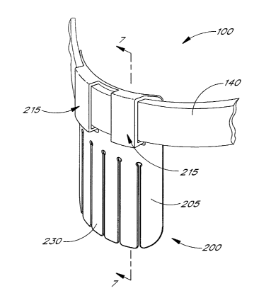
Referring to Figures 2-5, a skin pinch guard 200 includes a body 205 and a
pair of
fasteners 215, which permit easy attachment and removal of pinch guard 200 to
and from
lower cuff 140. Body 205 has a thin, relatively stiff shell-like configuration
and is
preferably, generally arcuate in cross-section to conform to a user's leg. A
centrally located
notch 202 provides some bendability for better conformance.
In the embodiment illustrated, each of the fasteners 215 is a generally
rectangular
element 215a that is attached at its upper end to the body 205 by a box-like
shell or
connector 215b. The shell spaces the element 215a forwardly from the adjacent
surface of
the body 205. This creates a space 216 between the element and the otherwise
forward face
of the body 205. However, as can be seen, there is actually an opening 220 in
the body
which is aligned with the fastener. Hence, the portion of the element 215a
below the
connector 215b is free to flex about the connector. Notches 222 in the edges
of the opening
220 adjacent the connector 215b facilitate the flexing action. The element
215a may
include an inwardly extending flange 225 on its lower end, as shown in Figures
2 and 3.
The flange serves as a retention element for the skin guard 200 as explained
below. In an
alternative embodiment, the free end of the fastener may be tapered inwardly
to serve as a
retention element, as shown in Figure 8.
The rear surface of the element 215a is preferably smooth and slightly curved
consistent with the curvature of the body 205 and the cuff 140 of the knee
brace. The front
surface of the element 215a preferably has a plurality of spaced,
strengthening ribs 210. As
seen, the ribs are vertically oriented and tapered from a central higher area
to lower ends.
The lower portion of the body 205 of pinch guard 200 beneath the fasteners 215
includes a plurality of forgers 230 that allow the pinch guard 200 to better
conform to the
shape of each user's leg while providing relief from pinching.
In a preferred embodiment, skin pinch guard 200 is formed from an injection
molded plastic material, such as polypropylene. However, any material having
sufficient
rigidity and flexibility to provide relief from pinching is contemplated
herein. As can be
appreciated from the description, skin pinch guard 200 is an optional
component of knee
brace 100 and need not necessarily be included therewith.
Figure 6 shows skin pinch guard 200 in use attached to knee brace 100.
Fasteners
215 are removably attached to lower cuff 140 while fingers 230 are to extend
into a ski
boot. Fasteners 215 hook over cuff 140, such that body 205 is behind the knee
brace 100,
-5-
CA 02457924 2004-02-13
WO 03/017891 PCT/US02/28084
as viewed in Figure 6, so that pinch guard 200 rests against the leg, with the
fasteners 215
external of the knee brace cuff. Figure 7 shows the attachment of fasteners
215 to cuff 140
using a retention element 225, in detail. In installation, the lower end of
the fastener flexes
outwardly and the cuff 140 slips into the space between the fastener and the
body of the
guard. Figure 8 shows an alternative embodiment, wherein fasteners 21 S are
tapered to
ensure securement of the fasteners to cuff 140.
Skin pinch guard 200 slides along the wearer's calf between the ski boot and
the
bottom of the proximal cuff 140 to prevent pinching. The fingers 230 extend
down into the
boot in a resting position. As the user flexes his leg, the boot slides up the
body 205 along
fingers 230. Hence, at one extreme, the tips of fingers 230 are within the
boot, while at the
other extreme, larger portions of the fingers 230 are within the boot. The ski
boot slides
with respect to guard 200 preventing skin from being pinched between the boot
and cuff
140 of the knee brace. The user preferably wears the guard under the sock.
Although the device has been described with reference to ski boots, it is
envisioned
that the skin pinch guard may be used in any activity in which skin may become
pinched
between footwear and a knee brace.
Although the present invention has been described in terms of preferred
embodiments,
other embodiments of the invention including variations in dimensions,
configuration and
materials will be apparent to those of skill in the art in view of the
disclosure herein. For
example, various other techniques for securing the guard to the brace cuff
include snaps,
Velcro fasteners, rivets, screws, adhesive, etc. In addition, all features
discussed in
connection with any one embodiment herein can be readily adapted for use in
other
embodiments herein. The use of different terms or reference numerals for
similar features in
different embodiments does not imply differences other than those which may be
expressly
set forth. Accordingly, the present invention is intended to be described
solely by reference to
the appended claims, and not limited to the preferred embodiments disclosed
herein.
-6-