Note: Descriptions are shown in the official language in which they were submitted.
CA 02457988 2004-02-18
ACELP/TCX Audio Coding 2 of 2
TABLE OF CONTENT
Section Page
BACKGROUND OF THE INVENTION 4
1. Field of the invention 4
2. Brief description of the prior art 4
OBJECTIVE OF THE INVENTION 13
SUMMARY OF THE INVENTION 13
BRIEF DESCRIPTION OF THE DRAWINGS 15
DETAILED DESCRIPTION OF AN ILLUSTRATIVE EMBODIMENT18
OVERVIEW OF THE ENCODER 18
High-level view of the encoder 18
Super-frame configurations 19
Mode selection 20
Overview of TCX mode 23
Overview of the bandwidth extension 24
Encoding parameters 24
Bit allocations in the illustrative embodiment 26
DETAILED DESCRIPTION OF THE ENCODER 28
Pre-processing and analysis filterbank 28
LF encoding 29
ACELP mode 31
Codebook gain quantization in ACELP mode 32
TCX mode 34
Windowing in TCX modes 35
Time-frequency mapping 39
Pre-shaping (low-frequency emphasis) 40
Split multi-rate lattice vector quantization 42
Optimization of the global gain and noise-fill 43
factor
Mufti-rate lattice Vector Quantization 49
CA 02457988 2004-02-18
ACELP/TCX Audio Coding 3 of 3
Handling of bit budget overflow and indexing of 50
splits
Quantized spectrum de-shaping 52
HF encoding 54
DETAILED DESCRIPTION OF THE DECODER 57
Main demultiplexing 57
Mode extrapolation 58
Decoding of the LF signal : ACELP/TCX decoding 60
ACELP / TCX switching 63
ACELP decoding 65
TCX decoding 67
Decoding of the high-frequency (HF) signal 72
Post-processing and synthesis filterbank 80
MULTIPLEXING OF ALGEBRAIC VQ PARAMETERS (Annex 1) 82
Formating of the ACELP / TCX bit stream 94
TCX GAIN ENCODING AND MULTIPLEXING 96
TABLE A-1 : LIST OF THE KEY SYMBOLS 99
REFERENCES 105
CA 02457988 2004-02-18
ACELP/TCX Audio Coding 4 of 4
BACKGROUND OF THE INVENTION
1. Field of the Invention
The present invention relates generally to encoding and decoding
of sound signals in digital transmission and storage systems, and more
specifically to hybrid transform and code-excited linear prediction coding.
2. Brief Description of the Prior Art
The digital representation of information offers many well-known
advantages. In the case of audio signals, the information (e.g. a speech or
music signal) is usually digitized using the PCM (Pulse Code Modulation)
format. The signal is thus sampled and quantized with usually 16 or 20 bits
per sample. Although simple, the PCM representation results in a high bit
rate (in number of bits per second or bit/s). This limitation is the main
motivation for designing efficient source coding techniques which can
reduce the source bit rate and meet the specific constraints of an
application in terms of audio quality, coding delay, and complexity.
An audio encoder converts a sound signal into a digital bitstream
which is transmitted over a communication channel or stored in a storage
medium. We consider here only lossy source coding (i.e. signal
compression). The role of the encoder is then to represent the PCM
samples with a smaller number of bits while maintaining a good subjective
audio quality. The decoder or synthesizer operates on the transmitted or
stored bit stream and converts it back to a sound signal. The reader is
referred to (Jayant, 1984) and (Gersho, 1992) for an introduction to signal
compression methods, to the general chapters of (Kleijn, 1995) for an in-
depth coverage of modern speech and audio coding techniques.
In the state of the art of high-quality audio coding, two classes of
algorithms can be distinguished ; Code-Excited Linear Prediction (CELP)
coding which is designed to encode primarily speech signals, and
CA 02457988 2004-02-18
ACELP/TCX Audio Coding 5 of 5
perceptual transform (or sub-band) coding which is well adapted to
represent music signals. These techniques can achieve a good
compromise between subjective quality and bit rate. CELP coding has
been developed in the context of low-delay bi-directional applications such
as telephony or conferencing, where the audio signal is typically sampled
at 8 or 16 kHz. On the other hand, perceptual transform coding has been
applied mostly to wideband high-fidelity music signals sampled at 32, 44.1
or 48 kHz for streaming or storage applications.
CELP coding (Atal, 1985) is the core framework of most modern
speech coding standards. In this coding model, the speech signal is
processed in successive blocks of N samples called frames, where N is a
predetermined number of samples corresponding typically to 10-30 ms.
The reduction of bit rate is achieved by removing the temporal correlation
between successive speech samples through linear prediction and using
efficient vector quantization (VQ). A linear prediction (LP) filter is
computed
and transmitted every frame. The computation of the LP filter typically
needs a look-ahead, a 5-10 ms speech segment from the subsequent
frame. In general, the N sample frame is divided into smaller blocks called
sub-frames, so as to apply pitch prediction. Usually the sub-frame length is
usually set in the range 4-10 ms. In each sub-frame, an excitation signal is
usually obtained from two components, a portion of the past excitation and
the innovative (or fixed-codebook) excitation. The component formed from
the past excitation is often referred to as the adaptive codebook or pitch
excitation. The parameters characterizing the excitation signal are coded
and transmitted to the decoder, where the reconstructed excitation signal
is used as the input of the LP filter. An important instance of CELP coding
is the ACELP (Algebraic CELP) coding model, whereby the innovative
codebook consists of interleaved signed pulses.
The CELP model has been developed in the context of narrow-
band speech coding, for which the input bandwidth is 300-3400 Hz. In the
case of wideband speech signals defined in the 50-7000 Hz band, the
CELP model is usually used in a split-band approach, where a lower band
CA 02457988 2004-02-18
ACELP/TCX Audio Coding 6 of 6
is represented by waveform matching (CELP coding) and the higher-band
is parametrically encoded. This band splitting has several motivations.
Most of the bits can be allocated in a frame to the lower-band signal to
maximize quality; the computational complexity (of filtering, etc.) can be
reduced compared to a full-band encoding; also, waveform matching is not
very efficient for high-frequency components. This split-band approach is
used for instance in the ETSI AMR-WB wideband speech coding standard.
This coding standard is specified in (3GPP TS 26.190) and described in
(Bessette, 2002). The implementation of AMR-WB is given in (3GPP TS
26.173). The AMR-WB speech coding algorithm consists essentially of
splitting the input wideband signal into a lower band (0-6400 Hz) and a
higher band (6400-7000 Hz), applying the ACELP algorithm only the lower
band and encoding the higher band by bandwidth extension (BW E).
The state-of-the-art audio coding techniques, e.g. MPEG-AAC or
ITU-T 6.722.1, are built upon perceptual transform (or sub-band) coding.
In transform coding, the time-domain audio signal is processed by
overlapping windows of appropriate length. The reduction of bit rate is
achieved by the de-correlation and energy compaction property of a
specific transform, as well as encoding only the perceptually relevant
transform coefficients. The windowed signal is usually decomposed
(analyzed) by a DFT, DCT or MDCT. A frame length of 40-60 ms is
normally needed to achieve good audio quality. However, to represent
transients and avoid time spreading of coding noise before attacks (pre-
echo), shorter frames of 5-10 ms are also used to describe non-stationary
audio segments. Quantization noise shaping is achieved by normalizing
the transform coefficients by scale factors prior to quantization. The
normalized coefficients are typically encoded by scalar quantization
followed by Huffman coding. In parallel, a perceptual masking curve is
computed to control the quantization process and optimize the subjective
quality: this curve is used to encode the most perceptually relevant
transform coefficients.
CA 02457988 2004-02-18
ACELP/TCX Audio Coding 7 of 7
To improve the coding efficiency (in particular a low bit rates), band
splitting can also be used with transform coding. This approach is used for
instance in the new High Efficiency MPEG-AAC standard (also known as
aacPlus). In aacPlus, the signal is split into two sub-bands, the lower-band
signal is encoded by perceptual transform coding (AAC), while the higher-
band signal is described by so-called Spectral Band Replication (SBR)
which is a kind of bandwidth extension (BWE).
In applications, such as audio/video conferencing, multimedia storage and
Internet audio streaming, the audio signal consists typically of speech,
music and mixed content. As a consequence, it is desirable in such
applications to employ an audio coding technique robust to the type of
input signal. In other words, the audio coding algorithm should achieve a
good and consistent quality for a wide class of audio signals, including
speech and music. Nonetheless, the CELP technique is known to be
intrinsically speech-optimized and has problems with music signals. State-
of-the art perceptual transform coding on the other hand has good
performance for music signals, but is not appropriate for representing
speech signals, especially at low bit rates.
Several approaches have then been considered to encode general
audio signals (including both speech and music) with a good and fairly
constant quality. Transform predictive coding (Moreau, 1992),
(Lefebvre,1994), (Chen, 1996), (Chen,1997) provides in particular a good
foundation for the inclusion of both speech and music coding techniques
into a single framework. This approach combines linear prediction and
transform coding. We will consider hereafter only the technique of
(Lefebvre, 1994), called TCX (Transform Coded eXcitation) coding, which
is equivalent to (Moreau, 1992), (Chen, 1996) and (Chen,1997).
Originally, two variants of TCX coding have been designed
(Lefebvre, 1994): one for speech signals using short frames and pitch
prediction, another for music signals with long frames and no pitch
CA 02457988 2004-02-18
ACELP/TCX Audio Coding 8 of 8
prediction. In both cases, the processing involved in TCX coding can be
decomposed in two steps:
1 ) The current frame of audio signal is processed by temporal
filtering to obtain a so-called target signal, and then
2) The target signal is encoded in transform domain.
Transform coding of the target signal uses a DFT with rectangular
windowing. Yet, to reduce blocking artifacts at frame boundaries, a
windowing with small overlap has been used in (Jbira, 1998) before the
DFT. In (Ramprashad, 2001 ), a Modified Discrete Cosine Transform
(MDCT) with windowing switching is used instead ; the MDCT has the
advantage to provide a better frequency resolution than the DFT while
being a maximally-decimated filter-bank. However, in the case of
(Ramprashad, 2001 ), the encoder does not operate in closed-loop, in
particular for pitch analysis. In this respect, the encoder of (Ramprashad,
2001 ) can not be qualified as a variant of TCX.
The representation of the target signal plays a crucial role in TCX coding
and controls an essential part of the TCX audio quality, because it
consumes most of the available bits in every coding frame. We restrict
ourselves here to transform coding in the DFT domain. Several methods
have been proposed to encode the target signal in this domain, see for
instance (Lefebvre, 1994), (Xie, 1996), (Jbira,1998) (Schnitzler, 1999) and
(Bessette, 1999). All these methods implement a form of a gain-shape
quantization, meaning that the spectrum of the target signal is first
normalized by a factor (or global gain) g prior to the actual encoding. In
(Lefebvre, 1994), (Xie, 1996) and (Jbira, 1998), this factor g is set to the
r.m.s (root mean square) of the spectrum. However, in general, it can be
optimized in each frame by testing different values of g, as in (Schnitzler,
1999) and (Bessette, 1999). Note that the actual optimisation of g in
(Bessette, 1999) has not been disclosed. To improve the quality of TCX
CA 02457988 2004-02-18
ACELP/TCX Audio Coding 9 of 9
coding, noise fill-in (i.e. the injection of comfort noise in lieu of
unquantized
coefficients) has been used in (Schnitzler, 1999) and (Bessette, 1999).
As explained in (Lefebvre, 1994), TCX coding can quite successful
encode wideband signals (i.e. signals sampled at 16 kHz): the audio
quality is good for speech at 16 kbit/s and for music at 24 kbit/s. Yet, TCX
coding is not as efficient as ACELP coding for encoding speech signals.
For this reason, a switched ACELPITCX coding strategy has been
presented briefly in (Bessette, 1999). The principle of ACELP/TCX coding
is similar for instance to the ATCELP (Adaptive Transform and CELP)
technique of (Combescure, 1999). Obviously, the audio quality can be
maximized by switching between different modes, which are actually
specialized to encode a certain type of signal. For instance, CELP coding
is specialized for speech and transform coding is more adapted to music,
so it is natural to combine these two techniques into a multimode
framework so that each audio frame can be encoded adaptively with the
most appropriate coding tool. In ATCELP coding, the switching between
CELP and transform coding is not seamless (i.e. it requires transition
modes) ; furthermore, an open-loop mode decision is applied, i.e. the
mode decision is made prior to encoding based on the available audio
signal. On the contrary, ACELP/TCX has the advantage of using two
homogeneous linear predictive modes (ACELP and TCX coding), which
makes switching easier ; moreover, the mode decision is closed-loop,
meaning that all coding modes are tested and the best synthesis is
selected.
Note that the ACELP/TCX mode decision used in (Bessette, 1999) has
never been disclosed in the prior art. Furthermore, the quantization of the
TCX target signal in ACELP/TCX coding has not been disclosed into
details in (Bessette, 1999). The underlying quantization method is only
known to be based on self scalable multi-rate lattice vector quanfization,
which was introduced in (Xie, 1996).
CA 02457988 2004-02-18
ACELP/TCX Audio Coding 10 of 10
The reader is referred to (Gibson, 1988) (Gersho, 1992) for an
introduction to lattice vector quantization. An N dimensional lattice is a
regular array of points in the N-dimensional (Euclidean) space. For
instance, (Xie, 1996) uses an 8-dimensional lattice, known as the Gosset
lattice, which is defined as:
REa=2Da v~2Da +( 1,~ ~ ~,1 )~ (Eq. 1 )
where
Da=~(.~,---,xa~ZB~x~+~~~+~ is odd (Eq. 2)
and
Da+(1,...~1)=~(x~+1,...,xs+1~Z8~(~; ..~.~~D gl (Eq- 3)
This mathematical structure allows to quantize a block of 8 real numbers.
RE8 can be also defined more intuitively as the set of points (x,, ..., x8)
verifying the properties:
i. The components x; are signed integers (for i=1,...,8)
ii. The sum xl+...+x8 is a multiple of 4
iii. The components x; have the same parity (for i=1,...,8), i.e. they are
either all even, or all odd.
An 8-dimensional quantization codebook can then be obtained by selecting
a finite subset of REg. Usually the mean-square error is the codebook
search criterion. In the technique of (Xie, 1996), 6 different codebooks,
called Q0, Q,, ..., Q5, are defined based on the RE8 lattice. Each
codebook, Q~ where n=0..5, comprises 24" points, which corresponds to a
rate of 4n bits per 8-dimensional sub-vector or N2 bit per sample. The
spectrum of TGX target, normalized by a scaled factor g, is then quantized
CA 02457988 2004-02-18
ACELP/TCX Andio Coding 11 of 11
by splitting it into 8-dimensional sub-vectors (or sub-bands). Each of these
sub-vectors is encoded into one of the codebooks Qo, Q,, ..., Q5. As a
consequence, the quantization of the TCX target (after normalization by
the factor g) produces for each 8-dimensional sub-vector a codebook
number n indicating which Q" has been used and an index i identifying a
specific code-vector in Q". This quantization process is referred to as multi-
rate lattice vector quantization, for the codebooks Q" have different rates.
The TCX mode of (Bessette, 1999) follows the same principle, yet no
details are provided on the computation of the normalization factor g nor
on the multiplexing of quantization indices and codebooks numbers.
The lattice vector quantization technique of (Xie, 1996) based on
REe has been extended in (Ragot, 2002) to improve efficiency and reduce
complexity. However, the application of the device of (Ragot, 2002) to TCX
coding has never been described in the prior art.
In the device of (Ragot, 2002), an 8-dimensional vector is coded
with multi-rate quantizer that employs a set of RE8 codebooks denoted as
{Qo, Qz, Q3, ..., Q3s}. The codebook Q, is not defined in the set in order to
improve coding efficiency. All cadebooks Q" are constructed as subsets of
the same 8-dimensional RE8 lattice, Q" c REB. The bit rate of the nth
codebook defined as bits per dimension is 4n/8, i.e. each codebook Q"
contains 24" code-vectors. The construction of the multi-rate quantizer
follows the before-mentioned reference. For a given 8-dimensional input
vector, the encoder of the multi-rate quantizer finds the nearest neighbor in
RE8, and outputs a codebook number n and an index i in Q~. Coding
efficiency is improved by applying an entropy coding technique for the
quantization indices (i.e. codebook numbers n and indices i of the splits).
In (Ragot, 2002), a codebook number n is coded prior to multiplexing to the
bitstream with an unary code that comprises a n - 1 ones and a zero stop
bit. The codebook number represented with the unary code is denoted by
nE. No entropy coding is employed for codebook indices i. The unary code
and bit allocation of nE and f is exemplified in Table 1.
CA 02457988 2004-02-18
ACELP/TCX Audio Coding 12 of 12
Table 1
The number of bits required to index the codebooks.
Codebook Unary Number I~lumber Number
number code of of of
nk n~ bits for bits for bits per
in binaryn~ ik split
form
0 0 1 0 1
2 LO 2 8 10
3 110 3 12 15
4 1110 4 16 20
s 11110 s 20 2s
As illustrated in Table 1, one bit is required for coding the input vector
when n = 0 and otherwise 5n bits are required.
Furthermore, an important practical issue in audio coding is the
formatting of the bitstream and the handling of bad frames, also known as
frame-erasure concealment. The bitstream is usually formatted at the
coding side as successive frames (or blocks) of bits. Due to channel
impairments (e.g. CRC violation, packet loss or delay, etc.j, some frames
may not be received correctly at the decoding side. In such a case, the
decoder typically receives a flag declaring a frame erasure and the bad
frame is "decoded" by extrapolation based on the past history of the
decoder. A common procedure to handle bad frames in CELP decoding
consists of reusing the past LP synthesis filter, and extrapolating the
previous excitation.
To improve the robustness against frame losses, parameter
repetition (also know as Forward Error Correction or FEC coding) may be
used.
Note that the problem of frame-erasure concealment for TCX or
switched ACELP/TCX coding has never been addressed in the prior art.
CA 02457988 2004-02-18
ACELP/TCX Audio Coding 13 of 13
OBJECTIVE OF THE INVENTION
An objective of the invention is therefore to disclose methods for
efficient audio coding using a switched ACELP/TCX model and lattice
(algebraic) quantizers, along with a low bit-rate bandwidth extension
method for encoding the higher frequencies. Methods far multiplexing the
associated variable-length frames into fixed-length packets are also
disclosed, along with packet loss concealment methods appropriate for the
disclosed hybrid encoder.
SUMMARY OF THE INVENTION
More particularly, in accordance with the present invention, there
are provided methods for
switching between ACELP and TCX modes in a hybrid audio
coding structure, with proper windowing and filter memory
updates;
- selecting optimal coding modes and frame lengths (ACELP
versus TCX of different length) in a closed-loop manner;
- applying bit-rate scalable lattice codebooks, in particular an
extension of the Gosset lattice in 8-dimensions, to the gain-
shape split vector quantization of a signal spectrum (in TCX
modes);
- reducing the complexity of said gain-shape split vector lattice
quantization by applying a novel gain estimation method,
which ensures that the spectrum divided by the estimated gain
will require close to the bit budget for indexing the selected
lattice points after quantization;
CA 02457988 2004-02-18
ACELPlTCX Audio Coding 14 of 14
- shaping the low-frequency coding noise in a transform coding
mode (such as TCX) by applying a novel signal adaptive
spectrum pre-shaping algorithm, and corresponding de-
shaping;
- enhancing the performance of an ACELP-type (in particular,
AMR-WB) coder for large transients, by encoding the
innovative codebook gain using a form of mean-removed
memoryless quantization;
- encoding the high-frequency signal (in the invention,
frequencies above 6400 Hz) at low bit rate using a novel
bandwidth extension method;
- splitting the bits of an encoded super-frame (80-ms of length,
in the invention) into several transmission packets, while
managing the possible bit overflow into one or more of the
transmission packets;
- improving the robustness of TCX decoding in case of missing
packets, by adding proper redundancy in the transmission of
the TCX gain across the transmission packets;
The objectives, advantages and other features of the present
invention will become more apparent upon reading of the following, non
restrictive description of a illustrative embodiment thereof, given by way of
example only with reference to the accompanying drawings.
CA 02457988 2004-02-18
ACELP/TCX Audio Coding 15 of 15
BRIEF DESCRIPTION OF THE DRAWINGS
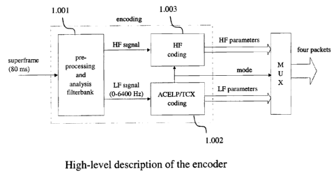
Figure 1 gives a high-level description of the encoder in the
invention.
Figure 2 gives the timing structure of the frame types in a super-
frame.
Figure 3 shows the payload structure of a packet for all frame
types (in the disclosed invention, a frame can be 20-ms ACELP, of 20-ms
TCX, or part of a 40-ms TCX or part of an 80-ms TCX).
Figure 4 shows the windowing used for linear predictive analysis,
along with the interpolation factors used at each 5-ms sub-frame
depending on the mode.
Figure 5 shows the frame windowing in ACELP/TCX encoder,
depending on the present frame mode and lengtht, and the past frame
mode.
Figure 6 is a high-level flow chart of the encoder for the TCX
modes.
Figure 6a gives an example spectrum and associated weighting
function, for the spectrum pre-shaping method disclosed in the invention.
Figure 7 shows in a block diagram how algebraic encoding is used
to quantize a set of coefficients (here, frequency coefficients) based on a
previously described self-scalable multi-rate lattice vector quantizer using
the RE$ lattice.
Figure 8 describes the iterative global gain estimation, for the TCX
encoder. The global estimation is a critical step in TCX encoding using
CA 02457988 2004-02-18
ACELP/TCX Audio Coding 16 of 16
lattice a lattice quantizer, to reduce the complexity while remaining within
the bit budget for the frame.
Figure 9 illustrates the principle of global gain estimation and
noise level estimation (in TCX frames).
Figure 10 is a flowchart showing the handling of the bit budget
overflow is managed in TCX encoding, when calculating the lattice point
indices of the splits.
Figure 11 gives a block diagram describing the encoder for the HF
signal (based on bandwidth extension).
Figure 11 a shows the gain matching procedure between the low
and high frequency envelope (computed in Processor 11.007 of Figure
11 ).
Figure 12 is a high-level block diagram of the decoder
(recombination of the LF signal, encoded with hybrid ACELP/TCX, and the
HF signal, encoded using bandwidth extension).
Figure 13 is a high-level block diagram of the mode extrapolation
device, used when missing packets occur at the decoder.
Figure 14 is a more detailed flowchart of the mode extrapolation
device.
Figure 15 illustrates the principle of ACELP/TCX decoding (for the
LF signal).
Figure 16 is a flowchart showing the logic in ACELP/TCX
decoding, when processing the 4 packets forming an 80-ms frame.
CA 02457988 2004-02-18
ACELP/'fCX Audio Coding 17 of 17
Figure 17 is a block diagram showing the ACELP decoding
principle in the invention (details of Processor 15.007 in Figure 15).
Figure 18 is a block diagram showing the ACELP decoding
principle in the invention (details of Processor 15.008 in Figure 15).
Figure 19 is a block diagram of the decoder for the HF signal,
based on the bandwidth extension method disclosed in the invention.
Figure 20 is non-existant and not used in the description of the
invention.
Figure 21 is a block diagram of the post-processing and synthesis
filterbank at the decoder side.
Figure 22 is a flow chart iluustrating the logic in TCX global gain
decoding in the presence of frame erasures, using the redundancy coding
disclosed in the invention.
Figure 23 is a block diagram of the LF encoder, showing how
ACELP and TCX encoders are tried in competition, using a segmental
SNR criterion to select the proper encoding mode for each frame in an 80-
ms super-frame.
Figure 24 is a block diagram showing the pre-processing and sub-
band decomposition applied at the encoder on each 80-ms super-frame.
CA 02457988 2004-02-18
ACELP/TCX Audio Coding 18 of 18
DETAILED DESCRIPTION OF A ILLUSTRATIVE EMBODIMENT
The illustrative embodiment of the invention discloses an audio
coding device extending the ACELP/TCX model of (Bessette, 1999) and
using the self-scalable multirate lattice vector quantization of (Ragot,
2002).
In the sequel, we first present an overview of the encoding
principle, then the details of a illustrative embodiment of the encoder and
decoder are presented.
OVERVIEW OF THE ENCODER
High-level view of the encoder
A high-level description of the encoder is shown in Fig. 1. The
input signal, sampled at 16 kHz or higher, is encoded in super-frames of T
ms, with T = 80 in the illustrative embodiment. Each super-frame is pre-
processed and split into two sub-bands, in a way similar to the pre-
processing of AMR-WB as disclosed in the prior art. The lower-frequency
(LF) and high-frequency (HF) signals are defined in the 0-6400 and 6400-
FmaX Hz bands, respectively, where F~,ax is the Nyquist frequency which
depends on the sampling frequency of the input signal.
The low-frequency signal (LF signal) is encoded by multi-mode
ACELP/TCX coding built upon the AMR-WB core that operates on 20-ms
frames within the 80-ms super-frame. The ACELP mode only operates on
20-ms frames since it is based on the AMR-WB encoding algorithm. The
TCX mode can operate on either 20, 40 or 80 ms frames within the 80-ms
super-frame. In the illustrative embodiment, the three TCX frame-lengths
of 20, 40, and 80 ms are used with an overlap of 2.5, 5, and 10 ms,
respectively. The overlap is necessary to reduce the effect of framing in
the TCX mode (as in transform coding). Figure 2 shows the timing chart of
CA 02457988 2004-02-18
ACELP/TCX Audio Coding 19 of 19
the frame types for ACELP/TCX coding of the LF signal. ACELP mode can
be chosen in any of the first, second, third and fourth 20-ms frame within
an 80-ms super-frame. Similarly, TCX mode can be used in any of the first,
second, third and fourth 20-ms frame within an 80-ms super-frame.
Additionally, the first two, or the last two, 20-frames can be grouped
together to form 40-frames to be encoded in TCX mode. Finally, the whole
80-ms super-frame can be encoded in one single 80-ms TCX frame.
Hence, in total, 26 different combinations of the three TCX frame types and
the ACELP frame are available to code an 80-ms super-frame. The frame
types to be used (ACELP or TCX and their length) in an 80-ms super-
frame are determined in closed-loop, as will be disclosed further.
The high-frequency signal (HF signal in Figure 1 ) is encoded using
a bandwidth extension approach. In bandwidth extension, an excitation-
filter parametric model is used, where the filter is encoded using few bits
and where the excitation is reconstructed at the decoder from the received
18LF signal excitation. In this invention, the frame types chosen for the
law-frequency band (ACELP/TCX) dictate directly the frame length used
for bandwidth extension in the 80-ms super-frame.
Super-frame configurations
All possible super-frame configurations are listed in Table 2 in the
form (m1, m2, m3, m4) where mk denotes the frame type selected for the kth
frame of 20 ms inside the super-frame such that
mk = 0 for 20-ms ACELP,
mk = 1 for 20-ms TCX,
mk = 2 for 40-ms TCX,
mk = 3 for 80-ms TCX.
For example, the configuration (1, 0, 2, 2) indicates that the 80-ms
super-frame is encoded by encoding the first 20-ms frame with20-ms TCX,
followed by encoding the second 20-ms frame with 20-ms ACELP and
CA 02457988 2004-02-18
ACELP/TCX Audio Coding 20 of 20
finally by encoding the last two 20-ms frames as a single 40-ms TCX
frame. Similarly, the configuration (3, 3, 3, 3) indicates that 80-ms TCX is
used for the whole super-frame.
(0, 0, (0, 0, (2, 2,
0, 0) 0, 1 0, 0)
)
( 1, 0, ( 1, (2, 2,
0, 0) 0, 0, 1, 0)
1 )
(0, 1, (0, 1, (2, 2,
0, 0) 0, 1 0, 1
) )
(1, 1, (1, 1, (2, 2,
0, 0) 0, 1) 1, 1)
(0, 0, {0, 0, (0, 0,
1, 0) 1, 1 2, 2)
)
(1, 0, (1, 0, (1, 0,
1, 0) 1, 1) 2, 2)
(0, 1, (0, 1, (0, 1, (2, 2,
1, 0) 1, 1 2, 2) 2, 2)
)
(1, 1, (1, 1, (1, 1, (3, 3,
1, 0) 1, 1) 2, 2) 3, 3)
Table 2. All possible 26 super-frame configurations.
Mode selection
The super frame configuration can be determined either by open-
loop or closed-loop decision. The open-loop method consists in selecting
the super-frame configuration following some analysis before the super-
frame encoding in a way to reduce the overall complexity. In closed-loop,
the approach consists in trying all super-frame combinations and choosing
the best one. A closed-loop decision generally provides higher quality
compared to open-loop decisions, with a tradeoff on complexity. In the
illustrative embodiment, the closed-loop decision is performed as
summarized in Table 3 and explained below.
In the closed-loop mode decision, all 26 possible super-frame
configurations of Table 2 can be selected with only 11 trials. The left half
of Table 3 (Trials) shows what encoding mode is applied to each 20-ms
CA 02457988 2004-02-18
ACELP/TCX Audio Coding 21 of 21
frame at each of the 11 trials. Fr0 to Fr3 refer to Frame 0 to Frame 3 in the
super-frame. The trial number (1 to 11) indicates a step in the closed-loop
mode-selection process. The final mode decision is known only after step
11. Note that each 20-ms frame is involved in only four of the 11 encoding
trials. When more than 1 frame is involved in a trial (lines 5, 10 and 11),
then TCX of the corresponding length is applied (TCX40 or TCX80). To
understand the intermediate steps of the mode decision process, the right
half of Table 3 gives an example of mode selection, where the final
decision (after trial 11 ) is 80-ms TCX. This would result in sending a value
of 3 for the mode in all four packets for this super-frame. Bold numbers in
the example at the right of Table 3 show at what point a mode decision is
taken in the intermediate steps of the mode selection process.
TRIALS (11 ) Example of selection
(in bold = comparison is made)
Fr 1 Fr 2 Fr 3 Fr 4 Fr 1 Fr 2 Fr 3 Fr 4
1 ACELP ACELP
2 TCX20 ACELP
3 ACELP ACELP ACELP
4 TCX20 ACELP TCX20
5 TCX40 TCX40 ACELP TCX20
6 ACELP ACELP TCX20 AGELP
7 TCX20 ACELP TCX20 TCX20
8 ACELP ACELP TCX20 TCX20 ACELP
9 TCX20 AGELP TCX20 TCX20 TCX20
10 TCX40 TCX40 ACELP TCX20 TCX40 TCX40
11 TCX80 TCX80 TCX80 TCX80 TCX80 TCX80 TCX80 TCX80
Table 3. Trials and example of closed-loop mode selection
CA 02457988 2004-02-18
ACELP/TCX Audio Coding 22 of 22
The mode selection process shown in Table 3 proceeds as
follows. First, in trials 1 and 2, ACELP (AMR-WB) then 20-ms TCX
encoding are tried on the first 20-ms frame (Fr0). Then, a mode selection
is made for Fr0 between these two modes. The selection criterion in the
illustrative embodiment is the segmental Signal-to-Noise Ratio (SNR)
between the weighted signal and the synthesized weighted signal. The
segmental SNR is computed using 5-ms segments. In the example of
Table 3, we assume that mode ACELP was retained. Then, in trial 3 and 4,
the same mode comparison is made for Fr1 between ACELP and 20-ms
TCX. Here, we assume that 20-ms TCX was better than ACELP, again
based on the segmental SNR measure disclosed above. This choice is
indicated in bold on line 4 of the example at the right of Table 3. Then, in
trial 5, Fr0 and Fr1 are grouped together to form a 40-ms frame which is
encoded using 40-ms TCX. The algorithm now has to choose between 40-
ms TCX for the first two frames, compared to ACELP in the first frame and
TCX20 in the second frame. In this example, on line 5 in bold, the
sequence ACELP-TCX20 was selected, according to the segmental SNR
criterion.
The same procedure as trials 1 to 5 is then applied to the third and
fourth frames (Fr2 and Fr3), in trials 6 to 10. After trial 10, in the example
of table 3, the four 20-ms frames are classified as : ACELP for FrO, then
TCX20 for Fr1, then TCX40 for Fr2 and Fr3 grouped together. A last trial
(line 11 ) is he performed when all four 20-ms frames (the whole super-
frame) are encoded with 80-ms TCX. Using the segmental SNR criterion,
again with 5-ms segments, this is compared with the signal encoded using
the mode selection in trial 10. In the example of Table 3, we assume that
the final mode decision is 80-ms TCX for the whole super-frame. The
mode bits for each 20-ms frame would then be (3,3,3,3) as discussed in
Table 2.
CA 02457988 2004-02-18
ACELP/TCX Audio Coding 23 of 23
Overview of the TCX mode
The closed-loop mode selection disclosed above implies that the
samples in a super-frame have to be encoded using ACELP and TCX
before making the mode decision. ACELP encoding is performed as in
AMR-WB. TCX encoding is performed as shown in the block diagram of
Figure fi. The TCX encoding principle is similar for TCX frames of 20, 40
and 80 ms, with a few differences mostly involving the windowing and filter
interpolation. The details of TCX encoding will be given in the detailed
description of the encoder. For now, we summarize the TCX encoding of
Figure 6 as follows. The input audio signal is filtered through a weighting
filter (same perceptual filter as in AMR-WB) to obtain a weighted signal.
The weighting filter coefficients are interpolated in a fashion which
depends on the TCX frame length. If the past frame was an ACELP frame,
the zero-input response (ZIR) of the weighting filter is removed from the
weighted signal. The signal is then windowed (the window shape will be
described in the detailed description) and a transform is applied to the
windowed signal. In the transform domain, the signal is first pre-shaped, to
minimize coding noise artifact in the low-frequencies, and then quantized
using a specific lattice quantizer that will be disclosed in the detailed
description. After quantization, the inverse pre-shaping function is applied
to the spectrum which is then inverse transformed to provide a quantized
time-domain signal. After gain resealing, a window is again applied to the
quantized signal to minimize the block effects of quantizing in the
transform domain. Overlap-and-add is used with the previous frame if it
was in also TCX mode. Finally, the excitation signal is found through
inverse filtering with proper filter memory updating. This TCX excitation is
in the same "domain" as the ACELP (AMR-WB) excitation.
The details of the TCX encoding principle shown in Figure 6 will be
described below.
CA 02457988 2004-02-18
ACELPITCX Audio Coding 24 of 24
Overview of the Bandwidth extension
Bandwidth extension is a method used to encode the HF signal at
low cost, in terms of bit-rate and complexity. In the illustrative embodiment,
we use an excitation-filter model to encode the HF signal. The excitation is
not transmitted at all; rather, the decoder extrapolated the HF signal
excitation from the received, decoded LF excitation. Hence, no bits are
required for the HF excitation signal. All the bits for the HF signal are used
to transmit an approximation of the spectral envelope. A linear LPC model
(the filter) is computed on the down-sampled HF signal of Figure 1. These
LPC coefficients can be encoded with few bits. This is because the
resolution of the ear decreases at higher frequencies, and the spectral
dynamics of audio signals also tends to be smaller at high frequencies. A
gain is also transmitted for every 20-ms frame. This gain is required to
compensate for the fact that the HF excitation signal (extrapolated from the
LF excitation signal) does not match the transmitted LPC filter for the HF
signal. The LPC filter is quantized in the ISF domain.
Coding in the low- and high-frequency bands is time-synchronous
such that bandwidth extension is segmented over the super-frame
according the mode selection in the lower band. The bandwidth extension
module will be disclosed in the detailed description of the encoder.
Encoding Parameters
The coding parameters can be divided into three categories as
shown in Figure 1; superframe configuration information (or mode
information), LF signal parameters and HF signal parameters.
The super-frame configuration can be coded using different
approaches. in particular, to meet specific systems requirements, it is often
desired to send large packets (as the 80-ms super-packets described
herein) as a sequence of smaller packets, corresponding to fewer bits and
possibly shorter duration. We disclose here the specific option of dividing
each 80-ms super-frame into four consecutive, smaller packets. For
CA 02457988 2004-02-18
ACELP/TCX Audio Coding 25 of 25
partitioning a super-frame into four packets, it is convenient to represent
the frame type chosen for each 20-ms frame inside a super-frame using
two bits to be included in the corresponding packet. This can be
accomplished readily by mapping an integer mk E {0, 1, 2, 3} into its
binary representation. Recall that mk is an integer describing the mode
selected for the kth 20-ms frame in a super-frame.
The low-frequency parameters depend on the frame type. In
ACELP frames, the parameters are the same as those of AMR-WB, in
addition to a mean-energy parameter used in this invention to improve the
performance of AMR-WB on attacks in music signals, as disclose here.
Specifically, when a 20-ms frame is encoded in ACELP mode (mode 0),
the parameters sent for that frame in the corresponding packet are
o The ISF parameters (46 bits reused from AMR-WB)
a The Mean energy (2 additional bits compared to AMR-WB)
o Pitch lag (as in AMR-WB)
o Pitch filter (as in AMR-WB)
o Fixed codebook indices (reused from AMR-WB)
o Codebook gains (as in 3GPP AMR-WB)
In TCX frames, ISF parameters are the same as in ACELP mode
(AMR-WB), but they are transmitted only once every TCX frame. For
example, if the super-frame is comprised of two 40-ms TCX frames, then
only two sets of ISF parameters are transmitted for the whole super-frame.
Similarly, if the super-frame is encoded as only one 80-ms TCX frame,
then only one set of ISF parameters is transmitted for that super-frame.
For each TCX frame (either 20ms, 40ms, 80ms) , the following parameters
are transmitted
o One set of ISF parameters (46 bits reused).
CA 02457988 2004-02-18
ACELP/T'CX Audio Coding 26 of 26
o Parameters describing the quantized spectrum coefficients in
the multi-rate lattice VQ (refer to Figure 6)
o Noise factor for noise fill-in (3 bits).
o Global gain (scalar, 7 bits).
These parameters and their encoding will be disclosed in the
detailed description of the encoder. Note that a large portion of the bit
budget in TCX frames is dedicated to the lattice VQ indices.
The high-frequency parameters, which are provided by the
Bandwidth extension, are typically only related to spectrum envelop and
energy. The following parameters are transmitted
o One set of ISF parameters (order 8, 9 bits) per frame (a frame
can be 20-ms ACELP, or 20-ms TCX, or 40-ms TCX or 80-ms
TCX)
o HF Gains (7 bits), quantized as a 4-dimensional gain vector,
with one gain per 20, 40 or 80-ms frame
o Gains correction (for 40-ms TCX and 80-ms TCX only) to
modify the more coarsely quantized HF gains in these TCX
modes.
Bit allocations in the illustrative embodiment
The ACELP/TCX codec in this illustrative embodiment can operate
at five bit rates : 13.6, 16.8, 19.2, 20.8 and 24.0 kbit/s. These bit rates
are
related to some of the AMR-WB rates, which is an integral part of the
invention. The corresponding number of bits to encode each 80-ms super-
frame at the five rates given above is 1088, 1344, 1536, 1664, and 1920
bits, respectively. In total, 8 bits are allocated far the super-frame
configuration (2 bits per 20-ms frame) and 64 bits for bandwidth extension
in each 80-ms super-frame. More or fewer bits could be used for the
bandwidth extension, depending on the resolution desired to encode the
CA 02457988 2004-02-18
ACELP/TCX Audio Coding 27 of 27
HF gain and spectral envelope. The remaining bit budget (i.e. most of the
bit budget) is used to encode the low frequency signal (LF signal in Figure
1 ). As an illustration, a typical bit allocation for the different frame
types is
detailed in Tables 4 and 5. The bit allocation of bandwidth extension is
shown in Table 6. These tables serves as an indication of the percentage
of the total bit budget typically used for encoding the different parameters
in the invention. Note that in tables 5b and 5c, corresponding respectively
to 40-ms and 80-ms TCX, the numbers in parentheses show the splitting of
the bits into two (table 5b) or 4 (table 5c) packets of equal size. For
example, table 5c indicates that in TCX-80 mode, the 46 ISF bits of the
super-frame (only one LPC filter for the super-frame) are split as : 16 bits
in the first packet, then 6 bits in the second packet, then 12 bits in the
third
packet and finally 12 bits in the last packet. Similarly, the algebraic VQ
bits
(most of the bit budget in TCX modes) are split into two packets (table 5b)
or four packets (table 5c). This splitting is done in such a way that the
quantized spectrum is split into two (table 5b) or four (table 5c) interleaved
tracks, where each track contains one out of every two (table 5b) or one
out of every four (table 5c) spectral block. Each spectral block is
composed of 4 successive complex spectrum coefficient. This interleaving
ensures that, if a packet is missing, it will only cause interleaved "holes"
in
the decoded spectrum for 40-ms TCX and 80-ms TCX. This splitting of bits
into smaller packets for 40-ms TCX and 80-ms TCX has to be done
carefully, to manage overflow when writing into a given packet.
CA 02457988 2004-02-18
ACELP/TCX Audio Coding 28 of 28
DETAILED DESCRIPTION OF THE ENCODER
In the illustrative embodiment, the audio signal is assumed to be sampled
in the PCM format at 16 kHz or higher, with a resolution of 16 bits per
sample. The role of the encoder is to compute and encode some
parameters based on this signal, and to transmit the encoded parameters
into the bitstream for decoding and synthesis purposes. A flag indicates to
the coder what is the input sampling rate.
The input signal is divided into successive blocks of 80 ms, which
will be referred to as super-frames hereafter. A simplified block diagram of
the encoder is shown in Figure 1. Each super-frame is pre-processed, and
then split into two sub-bands (Processor 1.001 ) in a way similar to AMR-
WB speech coding. The lower-frequency (LF) and high-frequency (HF)
signals are defined in the [0-6400] and [6400-11025] Hz bands,
respectively.
As was disclosed in the encoder overview, the low-frequency (LF)
signal is encoded by multimode ACELP/TCX coding (Processor 1.002),
while the high-frequency (HF) signal is coded by HF extension (Processor
1.003). The coding parameters computed in a given 80-ms super-frame
(i.e. the mode information, as well as the quantized HF and LF
parameters) are multiplexed into 4 packets of equal size.
In what follows, the main blocks of the diagram of Figure 1 (pre-
processing and analysis filter-bank, LF encoding and HF encoding) are
discussed in their respective details.
Pre-processing and analysis fiiterbank
Figure 24 shows a block diagram of the pre-processing and sub-band
decomposition in the illustrative embodiment of the encoder. The input
signal (a super-frame of 80-ms duration) is first separated in two sub-
CA 02457988 2004-02-18
ACELP/TCX Audio Coding 29 of 29
signals in Processors 24.001 and 24.002. The sub-signals are respectively
the Low-Frequency (LF) and High-Frequency (HF) signals in the output of
Processor 1.001. Hence, Processor 24.001 performs downsampling with
proper filtering to obtain the HF signal, and Processor 24.002 performs
downsampling with proper filtering to obtain the LF signal, in a method
similar to AMR-WB sub-band decomposition. The HF signal will then be
the input of the high-frequency coding module (Processor 1.003 in Figure
1 ). The LP signal is further pre-processed by two filters before being
passed to the LF signal encoding module (Processor 1.002 of Figure 1 )
first, the LF signal is filter with a high-pass filter having cutoff frequency
50
Hz (Processor 24.003) - this is to remove the DC component and the very
low frequency components ; then, after high-pass filtering, the LF signal is
filter with a deemphasis filter (Processor 24.004) to accentuate the high-
frequency components. This pre-emphasis is typical in wideband speech
coders.
LF encoding
A simplified block diagram of the LF encoding is shown in Figure 23. The
Figure shows in particular that ACELP and TCX modes (Processors
23.015 and 23.016) are always in competition within a super-frame. Note
however that the selector switch at the output of Processors 23.015 and
23.016 is such that each 20-ms frame within an 80-ms super-frame can be
encoded in either ACELP mode or part of a TCX mode (either 20, 40 or 80
ms). The mode selection is as explained in the overview of the encoder.
CA 02457988 2004-02-18
ACELP/TCX Audio Coding 30 of 30
The LF encoding therefore consists of two types of modes: an
ACELP mode applied on 20-ms frames and TCX. To optimize the audio
quality, the frame length of the TCX mode is allowed to be variable. The
TCX mode operates on 20, 40 or 80-ms frames. The actual timing
structure used in the encoder was shown in Figure 2.
In Figure 23, LPC analysis is first performed on the input LF signal noted
s(n). The window type, position and length for the LPC analysis is as
shown in Figure 4, where the windows are positioned with respect to an
80-ms segment of LF signal, plus look-ahead. Note that the windows are
positioned every 20 ms. After windowing, the LPC coefficients are
computed (every 20 ms), then transformed into ISP representation and
quantized for transmission to the decoder. The quantized ISP coefficients
are interpolated every 5 ms to smooth the evolution of the spectral
envelope. Processors 23.002 to 23.007 perform successively the
windowing, autocorrelation, lag windowing and noise correction, Levinson-
Durbin algorithm, ISP conversion, interpolation (in ISP domain) and
computation of the interpolated LPC filters (in Processor 23.007, which
outputs LPC parameters every 5 ms). Note that the ISP parameters are
transformed again into ISF parameters (Processor 23.008) before
quantization (Processor 23.009). The interpolated LPC parameters are
noted A(z), and the quantized version is noted A (z). The LF input signal
(s(n) in Figure 23) is then encoded both in ACELP mode (Processor
23.015) and in TCX mode (Processor 23.016), in all possible frame-length
combinations as explained in the encoder overview and as shown in
Figure 2. Note again that in ACELP mode, only 20-ms frames are
considered in an 80-ms superframe, whereas in TCX mode, frames of 20,
40 and 80 ms are considered in Processor 23.016. Then, when all possible
ACELP/TCX encoding combinations have been tried in Processors 23.015
and 23.016, all possible synthesis outputs (of Processors 23.015 and
23.016) are compared to the original signal in the weighted domain. It is
important to note that in the final selection, there can be a mixture of
ACELP and TCX frames in an encoded 80-ms super-frame, again as
specified in the encoding possibilities shown in Figure 2. The error signals
CA 02457988 2004-02-18
ACELP/TCX Audio Coding 31 of 31
computed by Processor 23.019 are in the weighted domain: both the input
LF signal (80-ms super-frame) and the synthesis output of Processors
23.015 and 23.016 are filtered with the perceptual filter formed by
Processors 23.013 and 23.018 (identical processors, even if they have
different ID numbers). For each possibility of the synthesis signal (again,
possibly a mixture of ACELP and TCX frames), Processor 23.020 then
computes the segmental Signal-to-Noise Ratio (SNR) over the whole 80-
ms super-frame. The segmental SNR operated on 5-ms sub-frames.
Computation of the segmental SNR is well known in the prior art. The
mode combination which minimizes the segmental SNR over the entire 80-
ms super-frame is then considered as the best encoding mode
combination. Again, we refer to table 2 for all 26 possible mode
combinations in a super-frame.
ACELP mode
The ACELP mode used in the illustrative embodiment is very similar to the
ACELP algorithm operating at 12.8 kHz in the AMR-WB speech coding
standard. The main changes compared to the ACELP algorithm in AMR-
W B are:
o The LP analysis (a different windowing is used in the illustrative
embodiment). The windowing used in the present invention for LPC
analysis is shown in Figure 4.
o as well as the quantization of the codebook gains in every 5-ms
sub-frame, as explained in the next section.
The ACELP mode operates on 5-ms sub-frames, where pitch analysis and
algebraic codebook search are performed every sub-frame.
CA 02457988 2004-02-18
ACELP/TCX Audio Coding 32 of 32
Codebook gain quantization in ACELP mode
In a given sub-frame of the ACELP mode, the two codebook gains
(pitch gain gp and code gain g~) are quantized jointly based on the 7-bit
gain quantization of AMR-WB. However, the Moving Average (MA)
prediction of g~, which is used in AMR-WB, is replaced in this invention by
an absolute reference which is coded explicitly. Thus, the codebook gains
are quantized here by a form of mean-removed quantization. This
memoryless (non-predictive) quantization is well justified, because the
ACELP mode may be applied to non-speech signals (e.g. transients in
music), which requires a more general quantization than the predictive
approach of AMR-WB which works well only for speech signals.
Computation and quantization of the absolute reference (in log domain):
A parameter, denoted ~,e"e,, is computed in open-loop and quantized
once per frame with 2 bits. The current 20-ms frame of LPC residual r =
(ro, ..., r~) is divided into 4 sub-frames, r;-(r;(0), ..., r,~Ls"b-1 )), with
i=0..3.
The parameter ~.l.ener is simply defined as the average of the sub-frame
energies (in dB) over the current frame of the LPC residual:
e.cene~(dB)=eo(dB)+e~(dB)+ez(dB)+e3(dB)
4
where
r(0)Z+...+r (lewb-1)z
ei =1+
leuG
is the energy of the i-th subframe of the LPC residual and
ea(dB)=101og~o {ey. A constant 1 is added to the actual sub-frame energy in
CA 02457988 2004-02-18
ACELP/TCX Audio Coding 33 of 33
the above equation to avoid the subsequent computation of the logarithm
of 0.
The mean ~,tener is then updated as follows:
I,Aener (dB) ~= 1-lever (dB) ' S * (p1 + p2)
where p; (I=1 or 2) is the normalized correlation computed as a side
product of the i-th open-loop pitch analysis. This modification of ~ener
improves the audio quality for voiced speech segments.
The mean /.lever (dB) is then scalar quantized with 2 bits. The
quantization levels are set with a step of 12 dB to 18, 30, 42 and 54 dB.
The quantization index can be simply computed as
tmp=(~ener-18)/12
index = floor(tmp+0.5)
if (index < 0) index =0, if (index > 3) index =3
The reconstructed mean (in dB) is: ,u ever (dB) =18+(index*12).
However, the index and the reconstructed mean are then updated to
improve the audio quality for transient signals such as attacks as follows:
max = max (e, (dB), e2 (dB), e3 (dB), e4 (dB))
if ,u ever (dB) < (max 27) and index <3,
index := IndeX +1, ,ll ever (dB) :_ ~(.l ever (dB) +1
Quantization of the codebook gains:
CA 02457988 2004-02-18
ACELP/TCX Audio Coding 34 of 34
Recall that in AMR-WB, the gains (gp and g~) are quantized jointly in
the form of (gp, g~ * goo) where goo combines a MA prediction for g~ and a
normalization with respect to the energy of the innovative code-vector.
In this invention, the two codebook gains (gp and g~) in a given sub-
frame are jointly quantized with 7 bits exactly as in AMR-WB speech
coding, in the form of (gp, g~*g~o). The only difference lies in the
computation of goo. The value of goo is based here on the quantized mean
energy ,u e"sr only, and computed as follows:
goo = 1 ~'((,~ ener (dB) - energy (dB) ) /20)
where
ener~ (dB) = 10 *1og10( 0.01 + (c(0)~2+...+c(Lsub-1)~2)/Lsub )
TCX mode
In the TCX modes (Processor 23.016), an overlap with the next
frame is defined to reduce blocking artifacts due to transform coding of the
TCX target signal. The windowing and signal overlap depends both on the
present frame type (ACELP or TCX) and size, and on the past frame type
and size. The windowing used in the illustrative embodiment will be
disclosed in the next section.
The TCX encoder employed in the illustrative embodiment is illustrated in
Figure 6. We now disclose the TCX encoding procedure, and we will then
go into more details about the lattice quantization used to quantize the
spectrum.
TCX encoding in the illustrative embodiment proceeds as follows.
CA 02457988 2004-02-18
ACELP/TCX Audio Coding 35 of 35
First, from Figure 6, the input signal is filtered through a weighting
filter (Processors 6.001 and 6.002) to produce the weighted signal. Note
that in TCX mode, the weighting filter uses the quantized LPC coefficients
A (z) instead of the unquantized A(z) as in ACELP. This is because,
contrary to ACELP which uses analysis-by-synthesis, the TCX decoder will
have to perform the apply the inverse weighting filter to recover the
excitation signal. If the previous encoded frame was ACELP, then the
zero-input response (ZIR) of the weighting filter is removed from the
weighted signal. In the illustrative embodiment, the ZIR is truncated to 10
ms and windowed in such a way that its amplitude monotonically
decreases to zero at after 10 ms. Several time-domain windows can be
used for this operation. The actual computation of this ZIR is not shown in
Figure 6 since this signal, also referred to as the "filter ringing" in CELP-
type coders, is well known to experts in the art. Once the weighted signal
is computed, the signal is windowed in Processor 6.003, according to the
window selection described in Figure 5.
After windowing by Processor 6.003, the windowed signal is
transformed into the frequency-domain using an FFT (Processor 6.004).
Windowing in the TCX modes -- Processor 6.003
One of the key aspects of the invention is the mode switching
between ACELP-type and TCX-type frames. To minimize the transition
artifacts, proper care has to be given to windowing and overlap of
successive frames. Adaptive windowing is performed by Processor 6.003.
Figure 5 shows the window shapes depending on the TCX frame length
and the type of the previous frame (ACELP of TCX). In Figure 5 (a), we
first consider the case where the present frame is a TCX frame of length
20 ms. Depending on the past frame, the window applied can be
CA 02457988 2004-02-18
ACELP/TCX Audio Coding 36 of 36
1 ) if the previous frame was an ACELP frame (of 20
ms duration) : the window is a concatenation of two
window segments - a flat window of duration 20 ms
followed by the half-right portion of the square-root of a
Hanning window of duration 2.5 ms - the encoder then
needs a lookahead of 2.5 ms of the weighted speech
2) if the previous frame was a TCX frame of 20 ms
duration : the window is a concatenation of three
window segments - first, the left-half of the square-root
of a Hanning window of 2.5 ms duration, then a flat
window of duration 17.5 ms, then the half-right portion
of the square-root of a Hanning window of duration 2.5
ms - the encoder again needs a lookahead of 2.5 ms
of the weighted speech
3) if the previous frame was a TCX frame of 40 ms
duration : the window is a concatenation of three
window segments - first, the left-half of the square-root
of a Hanning window of 5 ms duration, then a flat
window of duration 15 ms, then the half-right portion of
the square-root of a Hanning window of duration 2.5
ms - the encoder again needs a lookahead of 2.5 ms
of the weighted speech
4) if the previous frame was a TCX frame of 80 ms
duration : the window is a concatenation of three
window segments - first, the left-half of the square-root
of a Hanning window of 10 ms duration, then a flat
window of duration 10 ms, then the half-right portion of
the square-root of a Hanning window of duration 2.5
ms - the encoder again needs a lookahead of 2.5 ms
of the weighted speech
CA 02457988 2004-02-18
ACELP/TCX Audio Coding 37 of 37
In Figure 5 (b), we then consider the case where the present frame
is a TCX frame of length 40 ms. Depending on the past frame, the window
applied can be
1 j if the previous frame was an ACELP frame (of 20 ms
duration) : the window is a concatenation of two window
segments - a flat window of duration 40 ms followed by the
half-right portion of the square-root of a Hanning window of
duration 5 ms - the encoder then needs a iookahead of 5 ms of
the weighted speech
2) if the previous frame was a TCX frame of 20 ms duration
the window is a concatenation of three window segments -
first, the left-half of the square-root of a Hanning window of 2.5
ms duration, then a flat window of duration 37.5 ms, then the
half-right portion of the square-root of a Hanning window of
duration 5 ms - the encoder again needs a lookahead of 5 ms
of the weighted speech
3) if the previous frame was a TCX frame of 40 ms duration
the window is a concatenation of three window segments -
first, the left-half of the square-root of a Hanning window of 5
ms duration, then a flat window of duration 35 ms, then the
half-right portion of the square-root of a Hanning window of
duration 5 ms - the encoder again needs a lookahead of 5 ms
of the weighted speech
4) if the previous frame was a TCX frame of 80 ms duration
the window is a concatenation of three window segments -
first, the left-half of the square-root of the square-root of a
Hanning window of 10 ms duration, then a flat window of
duration 30 ms, then the half-right portion of the square-root of
a Hanning window of duration 5 ms - the encoder again needs
a lookahead of 5 ms of the weighted speech
CA 02457988 2004-02-18
ACELP/TCX Audio Coding 38 of 38
Finally, in Figure 5 (c), we consider the case where the present
frame is a TCX frame of length 80 ms. Depending on the past frame, the
window applied can be
1 ) if the previous frame was an ACELP frame (of 20 ms
duration) : the window is a concatenation of two window
segments - a flat window of duration 80 ms followed by the
half-right portion of the square-root of a Hanning window of
duration 5 ms - the encoder then needs a lookahead of 10 ms
of the weighted speech
2) if the previous frame was a TCX frame of 20 ms duration
the window is a concatenation of three window segments -
first, the left-half of the square-root of a Hanning window of 2.5
ms duration, then a flat window of duration 77.5 ms, then the
half-right portion of the square-root of a Hanning window of
duration 10 ms - the encoder again needs a lookahead of 10
ms of the weighted speech
3) if the previous frame was a TCX frame of 40 ms duration
the window is a concatenation of three window segments -
first, the left-half of the square-root of a Hanning window of 5
ms duration, then a flat window of duration 75 ms, then the
half-right portion of the square-root of a Hanning window of
duration 10 ms - the encoder again needs a lookahead of 10
ms of the weighted speech
4) if the previous frame was a TCX frame of 80 ms duration
the window is a concatenation of three window segments -
first, the left-half of the square-root of a Hanning window of
10 ms duration, then a flat window of duration 70 ms, then
the half-right portion of the square-root of a Hanning window
of duration 10 ms - the encoder again needs a lookahead of
10 ms of the weighted speech
CA 02457988 2004-02-18
ACELP/TCX Audio Coding 39 of 39
We note again that all these window types are applied to the weighted
signal, only when the present frame is a TCX frame. Frames of type
ACELP are encoded as in the prior art describing AMR-WB encoding (i.e.
through analysis-by-synthesis encoding of the excitation signal, so as to
minimize the error in the target signal - the target signal is essentially the
weighted signal to which the zero-input response of the weighting filter is
removed). We note also that, when encoding a TCX frame that is
preceded by another TCX frame, the windowed signal using the windows
described above is quantized directly in a transform domain - as will be
disclosed below. Then after quantization and inverse transformation, the
synthesized weighted signal is recombined using overlap-and-add at the
beginning of the frame with memorized look-ahead of the preceding frame.
On the other hand, when encoding a TCX frame preceded by an ACELP
frame, the zero-input response of the weighting filter (actually, a windowed
and truncated version of the zero-input response) is first removed from the
windowed weighted signal : since the zero-input response is a good
approximation of the first samples of the frame, the resulting effect is that
the windowed signal will tend towards zero both at the beginning of the
frame (because of the zero-input response subtraction) and at the end of
the frame (because of the half-Hanning window applied to the look-ahead
as described above and shown in Figure 5). Of course, the windowed and
truncated zero-input response is added back to the quantized weighted
signal after inverse transformation.
Hence, we achieve a suitable compromise between an optimal
window (e.g. Hanning window) prior to the transform used in TCX frames,
and the implicit rectangular window that has to be applied to the target
signal when encoding in ACELP mode. This ensures a smooth switching
between ACELP and TCX frames, while allowing proper windowing in both
modes.
Time-frequency mapping - Processor 6.004
CA 02457988 2004-02-18
ACELP/TCX Audio Coding 40 of 40
After windowing as described above, a transform is applied to the
weighted signal in Processor 6.004. In the illustrative embodiment, a Fast
Fourier Transform (FFT) is used.
Note (as shown in Figure 5) that TCX uses overlap between
successive frames to reduce blocking artifacts. The length of the overlap
depends on the length of the TCX modes: it is set respectively to 2.5, 5
and 10 ms when the TCX mode works with a frame length of 20, 40 and 80
ms (i.e. the length of the overlap is set to 1/8t" of the frame length). This
choice of overlap simplifies the radix in the fast computation of the DFT (by
FFT). As a consequence the effective time support of the TCX modes is
22.5, 45 or 90 ms, as shown in Figure 2. With a sampling frequency of
12,800 samples per second (in the LF signal produced by Processor
1.001 ), and with frame+lookahead durations of 22.5, 45 or 90 ms, the time
support of the FFT becomes 288, 576 or 1152 samples, respectively.
These lengths can be expressed as 9 times 32, 9 times 64 and 9 times
128. Hence, a specialized radix-9 FFT can be used to computed rapidly
the Fourier spectrum.
Pre-shaping (low-frequency emphasis) -- Processor 6.005.
Once the Fourier spectrum (FFT) is computed, an adaptive low-
frequency emphasis module is applied to the spectrum (Processor 6.005),
to minimize the perceived distortion in the lower frequencies. The inverse
low-frequency emphasis will be applied at the decoder, as well as in the
encoder (Processor 6.007) to allow obtaining the excitation signal
necessary to encode the next frames. The adaptive low-frequency
emphasis is applied only on the first quarter of the spectrum, as follows.
First, we call X the transformed signal at the output of the FFT
(Processor 6.004). The Fourier coefficient at Nyquist frequency is
CA 02457988 2004-02-18
ACELP/TCX Audio Coding 41 of 41
systematically set to 0. Then, if N is the number of samples in the FFT (N
is thus the window length), the K--N/2 complex-valued Fourier coefficients
are grouped in blocks of four consecutive coefficients, forming 8-
dimensional real-valued blocks. Note that block lengths of size different
than 8 can be used in general. In the illustrative embodiment, a block size
of 8 is chosen to coincide with the 8-dimensional lattice quantizer used for
spectral quantization. The energy of each block is computed, up to the first
quarter of the spectrum. The energy Emax and position index 1 of the block
with maximum energy are stored. Then, we calculate a factor fm for each
8-dimensional block with position index m smaller than I, as follows
o calculate the energy Em of the 8-dimensional block at
position index m
a compute the ratio Rm = Emax l Em
o compute the value (Rm) '~a
o if Rm > 10, then set Rm = 10
o also, if Rm > R(m-1 ) then Rm = R(m-1 )
This last condition ensures that the ratio function Rm decreases
monotonically. Further, limiting the ratio Rm to be smaller or equal to 10
means that no spectral components in the low-frequency emphasis
function will be modified by more than 20 dB.
After computing the ratio Rm = (Emaxl Em)'~4 for all blocks with
position index smaller that I (and with the limiting conditions described
above), we then apply these ratios as a gain for each corresponding
block. This has the effect of increasing the energy of blocks with relatively
low energy compared to the block with maximum energy Emax. Applying
CA 02457988 2004-02-18
ACELP/TCX Audio Coding 42 of 42
this procedure prior to quantization has the effect of shaping the coding
noise in the lower band.
Figure 6a shows an example spectrum on which the above
disclosed pre-shaping is applied. The frequency axis is normalized
between 0 and 1, where 1 is the Nyquist frequency. The amplitude
spectrum is shown in dB. In Figure 6a, the blue line is the amplitude
spectrum before pre-shaping, and the red line portion is the modified (pre-
shaped) spectrum. Hence, only the spectrum corresponding to the red line
is modified in this example. In Figure 6a, the actual gain applied to each
spectral component by the pre-shaping function is shown. We see that the
gain is limited to 10, and monotonically decreases to 1 as it reaches the
spectral component with highest energy (here, the third harmonic of the
spectrum) at the normalized frequency of about 0.18.
Split multi-rate lattice vector quantization -- Processor 6.006
After low-frequency emphasis, the spectral coefficients are
quantized using, in the illustrative embodiment, an algebraic quantizer
based on lattice codes. The lattices used are 8-dimensional Gosset
lattices, which explains the splitting of the spectral coefficients in 8-
dimensional blocks. The quantization indices are essentially a global gain
(from Processor 6.009) and a series of indices (from Processor 6.006)
describing the actual lattice points used to quantize each 8-dimensional
sub-vector in the spectrum. The lattice quantizer in Processor 6.006
performs (in a structured manner) a nearest neighbor search between
each 8-dimensional vector of the scaled pre-shaped spectrum and the
points in the lattice codebook used for quantization. The scale factor
(global gain) actually determines the bit allocation and the average
distortion. The larger the global gain, the more bits are used and the lower
the average distortion. For each 8-dimensional vector of spectral
coefficients, the lattice quantizer of Processor 6.006 outputs an index
which indicates the lattice codebook number used and the actual lattice
point chosen in the corresponding lattice codebook. The decoder will then
CA 02457988 2004-02-18
ACELP/TCX Audio Coding 43 of 43
be able to reconstruct the quantized spectrum using the global gain index
along with the indices describing each 8-dimensional vector. The details of
this procedure will be disclosed below.
Once the spectrum is quantized, the global gain (output of Processor
6.009) and lattice vectors indices (output of Processor 9.006) can be
transmitted to the decoder.
Optimization of the global gain and computation of the noise-fill
factor
A non-trivial step in using lattice vector quantizers is to determine the
proper bit allocation within a pre-determined bit budget. Contrary to stored
codebooks, where the index of a codebook point is basically its position in
a table, the index of a lattice codebook point is calculated using
mathematical (algebraic) formulae. The number of bits necessary to
encode the lattice vector index is thus only known after the input vector is
quantized. To insure staying within the pre-determined bit budget, this
would in principle require trying several global gains and quantizing the
normalized spectrum with each different gain to compute the total number
of bits required. The global gain which achieves the bit allocation closest to
the pre-determined bit budget, without exceeding it, would be chosen as
the optimal gain. In this invention, a heuristic approach is used instead, to
avoid having to quantize the spectrum several times before obtaining the
optimum quantization and bit allocation.
For the sake of clarity, the key symbols related to this part of the
illustrative embodiment of the invention are gathered in Table A-1.
Recall from Figure 6 that the time-domain TCX weighted signal x is
processed by a transform T and a pre-shaping P, which produces a
spectrum X to be quantized. In the illustrative embodiment of this
CA 02457988 2004-02-18
ACELP/TCX Audio Coding 44 of 44
invention, T is a FFT and the pre-shaping corresponds to the low-
frequency enhancement disclosed above.
We will refer to vector X as the pre-shaped spectrum. We assume that this
vector has the form X - [Xo X1 ... XN_ ~]T, where N is the number of
transform coefficients obtained from T (the pre-shaping P does not change
this number of coefficients).
Overview of the quantization procedure for the pre-shaped spectrum
In the illustrative embodiment of this invention, the pre-shaped
spectrum X is quantized as described in Figure 7. The quantization is
essentially based on the device of (Ragot, 2002). We assume an available
bit budget of RX bits for encoding X. As shown in Figure 7, X is quantized
by gain-shape split vector quantization in three main steps:
o An estimated global gain g, called hereafter the global gain, is
computed (Processors 7.001 and 7.002) and the spectrum X is
normalized (Processor 7.003) by this factor to obtain X'= X/g. X' is
thus the normalized pre-shaped spectrum.
o The multi-rate lattice vector quantization of (Ragot, 2002)
(Processor 7.004) is applied to all 8-dimensional blocks of
coefficients forming X', and the resulting parameters are
multiplexed. To be able to apply this quantization scheme, X' is
divided into K sub-vectors of identical size, so that X -
[X'oT X'~T ... X'K_ ~T]T, where the kth sub-vector (or split) is given by
X'k =[X8k... XgktK-1]~ IC=0, 1, ..., K-1.
Since the device of (Ragot, 2002) actually implements a form of 8-
dimensional vector quantization, K is simply set to 8. We assume
that N is a multiple of K.
o A noise fill-in gain fac is computed (in Processor 7.003) to later
inject comfort noise in un-quantized splits of X'. The unquantized
CA 02457988 2004-02-18
ACELP/TCX Audio Coding 45 of 45
splits are blocks of coefficients which have been set to zero by the
quantizer. The injection of noise allows to mask artifacts at low bit
rates and improves audio quality. A single gain fac is used (as
opposed to the prior art), because TCX coding assumes that the
coding noise is flat in the target domain and shaped by the inverse
perceptual filter hV(z)-'. Although pre-shaping is used here, the
quantization and noise injection relies on the same principle.
As a consequence, the quantization of X shown in Figure 7 produces three
kinds of parameters: the global gain g, the (split) algebraic VQ parameters
and the noise fill-in gain fac. The bit allocation (or bit budget) RX is
decomposed as:
RX = Rg + R + R fac
where Rg, R and Rfa~ are the number of bits (or bit budged allocated to g,
algebraic VQ, and fac, respectively. In the illustrative embodiment, Rfa~ = 0.
Note that the multi-rate lattice vector quantization of (Ragot, 2002)
is self-scalable and does not allow to control directly the bit allocation and
the distortion in each split. This is the reason why the device of (Ragot,
2002) is applied to the splits of X' instead of X. The global gain g therefore
plays a crucial role here, and its optimization controls the quality of the
TCX mode. In the illustrative embodiment of this invention, the
optimization of g is based on the log-energy of the splits.
In the sequel, each block of Figure 7 is detailed one by one.
Computing the Energy of Splits (Processor 7.001)
The energy (i.e. square-norm) of the split vectors plays a crucial
role in the bit allocation algorithm, and is employed for determining the
global gain (as well as the noise level). Recall that the N dimensional input
vector X = [xo x~ ... xN ,]T is partitioned into K splits, eight-dimensional
subvectors, such that the kth split becomes xk = [xak x$k+, ... x8k f~]T for k
CA 02457988 2004-02-18
ACELP/TCX Audio Coding 4G of 46
= 0, 1, ..., K 1. It is assumed that N is a multiple of eight. The energy of
the
kth split vector is computed as
ek = Xk Xk = Xgk + ... + Xgk f72, k= 0, ~ , ..., K ~
Estimation of the global gain and noise level (Processor 7.002)
The global gain g controls directly the bit consumption of the splits
and is solved from R(g) = R, where R(g) is the number of bits used (or bit
consumption) by all the split algebraic VQ for a given value of g. Recall
that R is the bit budget allocated to the split algebraic VQ. As a
consequence, the global gain g is optimized so as to match the bif
consumption and the bit budget of algebraic VQ. The underlying principle
is known as reverse water-filling in the literature.
To reduce the quantization complexity in the illustrative
embodiment, the actual bit consumption for each split is not computed, but
only estimated from the energy of the splits. This energy information
together with an a priori knowledge of multi-rate REg vector quantization
allows to estimate R(g) as a simple function of g.
The global gain is determined by applying this basic principle in Processor
7.002. The bit consumption estimate of the split Xk is a function of the
global gain g, and is denoted as R~(g). With the unity gain g = 1 we apply
the heuristics
R~( 1 ) = 5 loge (E + ek)l2, k = 0, 1, . . ., K-1
as a bit consumption estimate. The constant ~ > 0 prevents the
computation of loge 0, and the value s = 2 is used. In general the constant
~ is negligible compared to the energy of the split ek.
CA 02457988 2004-02-18
ACELP/TCX Audio Coding 47 of 47
The formula of R~(1 ) is based on a priori knowledge of the multi-
rate quantizer of (Ragot, 2002) and the properties of the underlying RE$
lattice:
o For the codebook number nk > 1, the bit budget requirement for
coding the kth split at most 5nk bits as can be confirmed from Table
1. This gives the factor 5 in the formula when loge (~ + ek)/2 is as an
estimate of the codebook number.
o The logarithm loge reflects the property that the average square-
norm of the codevectors is approximately doubled when using Q"k
instead of Qnk+,. The property can be observed from Table 4.
o The factor 1/2 applied to E + ek calibrates the codebook number
estimate for the codebook Q2. The average square-norm of lattice
points in this particular codebook is known to be around 8.0 (see
Table 4). Since loge (s + ez))/2 - log2 (2 + 8.0))/2 = 2, the
codebook number estimation is indeed correct for Q2.
Table 4
Some statistics on the square norms of the lattice points in different
codebooks.
n ' Average
Norm
0 0
2 8.50
3 20.09
4 42:23
93:85
6 1$2.49
7 362.74
When a global gain g is applied to a split, the energy of x~/g is
obtained by dividing ek by g2. This implies the bit consumption of the gain-
scaled split can be estimated based on R~(1 ) by subtracting 5 loge g2 =
loge g from it:
R~(9) = 5 loge (s + ek)l2g2
CA 02457988 2004-02-18
ACELP/TCX Audio Coding 48 of 48
- 5 loge (E + ek)/2 + 5 loge g2
- R~1 ) - 9~og (Eq. 4)
in which g,o9 = 10 loge g. The estimate R~(g) is lower bounded to zero, thus
the relation
R~(g) = max {R~(1 ) - g,o9, 0} (Eq. 5)
is used in practice.
The bit consumption for coding all K splits is now simply a sum
over the individual splits,
R(g) = Ro(g) + Ryg) + ... + RK_,(g). (Eq. 6)
The nonlinearity of equation 6 prevents solving analytically the global gain
g that yields the bit consumption matching the given bit budget, R(g) = R.
However, the solution can be found with a simple iterative algorithm
because R(g) is a monotonous function of g.
In this invention, the global gain g is searched efficiently by applying
a bisection search to go9 = 10 loge g, starting from the value g,o9 = 128. At
each iteration iter, R(g) is evaluated using (Eq. 4), (Eq. 5) and (Eq. 6), and
g,og is respectively adjusted as g,og := gio9 ~ 128/2't~~. Ten iterations give
a
sufficient accuracy. The global gain can then be solved from g,~ as g =
29iog /10 .
The flow chart of Figure 8 details the bisection algorithm employed
for determining the global gain. The algorithm provides also the noise level
as a side product. The algorithm starts by adjusting the bit budget R in
Processor 8.001 to the value 0.95(R - ~. The adjustment has been
determined experimentally in order to avoid an over-estimation of the
optimal global gain. The bisection algorithm requires as its initial value the
bit consumption estimates R~(1) for k = 0, 1, ..., K- 1 assuming a unity
global gain. These estimates are computed employing equation 5 in
Processor 8.003 having first obtained the square-norms of the splits ek in
CA 02457988 2004-02-18
ACELP/TCX Audio Coding 49 of 49
Processor 8.002. The algorithm starts from the initial values iter = 0, g~09 =
0, and 0 = 128/2'te~ = 128 set in Processor 8.004.
Each iteration in the bisection algorithm comprises an increment
gn9 := 9ng + 4 in Processor 8.006, and the evaluation of the bit
consumption estimate R(g) in Processors 8.007 and 8.008 with the new
value of g,og. If the estimate R(g) exceeds the bit budget R in Processor
8.009, the update of g,o9 is reversed in Processor 8.011. The iteration ends
by incrementing the counter iter and halving the step size O in Processor
8.010. After ten iterations, a sufficient accuracy for g,o9 is obtained and
the
global gain can be solved g = 2g'°9 "° in Processor 8.012. The
noise level
g~s is estimated in Processor 8.013 by averaging the bit consumption
estimates of those splits that are likely to be left unquantized with the
determined global gain g,og.
Figure 9 details the steps involved in determining the noise level
fac. The noise level is computed as the square root of the average energy
of the splits that are likely to be left un-quantized. For a given global gain
g~o9, a split is said to be likely to be un-quantized if its estimated bit
consumption is less than 5 bits, i.e. if R~(1 ) - g,o9 < 5. The total bit
consumption of all such splits, R~S(g), is obtained by summing Rk(1 ) - g,og
over the splits for which R~(1 ) - g,o9 < 5. The average energy of these
splits
can then be computed in log domain from Rns(g) as R"S (g)lnb, where nb is
the number of these splits. The noise level is
fag-2 H~.~~,~"6-5
In this equation, the constant -5 in exponent is a (conservative) tuning
factor which adjusts the noise factor 3 dB (in energy) below the real
estimated based on the average energy.
CA 02457988 2004-02-18
ACELP/TCX Audio Coding 50 of 50
Multi-Rate Lattice Vector Quantization (Processor 6.006)
The basic building block or Processor 6.006 is the multi-rate
quantization means disclosed and detailed in (Ragot, 2002) is applied. The
eight-dimensional splits of the normalized spectrum X' are coded with
multi-rate quantizer that employs a set of RE8 codebooks denoted as {Qo,
Q2, Qs, ...}. In the illustrative embodiment of the invention, the codebook
Q1 is not defined in the set in order to improve coding efficiency. The nth
codebook is denoted by Q" where n is referred to as a codebook number.
All codebooks Q" are constructed as subsets of the same 8-dimensional
RE$ lattice, Qr, c RE8. The bit rate of the nth codebook defined as bits per
dimension is 4n/8, i.e. each codebook Q" contains 24" code-vectors. The
construction of the multi-rate quantizer follows the before-mentioned
reference.
For the kth eight-dimensional split X'k, the encoder of the multi-rate
quantizer finds the nearest neighbor Yk in RE8, and outputs
o the smallest codebook number nk such that Yk E Q"k, and
o the index ik of Yk in Q"k.
The codebook number nk is a side information that has to be made
available to the decoder together with the index ik to reconstruct the
codevector Yk. By construction of the multi-rate quantizer, the size of index
ik is 4nk bits for nk > 1. This index can be represented with 4-bit blocks.
For nk = 0, the reconstruction yk becomes an eight-dimensional zero vector
and ik is not needed.
Handling of Bit Budget Overflow and Indexing of Splits (Processor
7.005)
For a given global gain g, the real bit consumption may either
exceed or remain under the bit budget. In this invention, a possible bit
CA 02457988 2004-02-18
ACELP/'1'CX Audio Coding 51 of 51
budget underflow is not addressed by any specific means, but the
available extra bits are zeroed and left unused. When a bit budget overflow
occurs, the bit consumption is accommodated into the bit budget Rx in
Processor 7.005 by zeroing some of the codebook numbers no, n,, ...,
nK_ 1. Zeroing a codebook number nk > 0 reduces the total bit consumption
at least by 5n,~1 bits. The splits zeroed in the handling of the bit budget
overflow are reconstructed at the decoder by noise fill-in.
To minimize the coding distortion that occurs when the codebook
numbers of some splits are forced to zero, these splits shall be selected
prudently. In a illustrative embodiment of the invention, the bit consumption
is accumulated by handling the splits one by one in an descending order of
their energy ek = xk xk for k = 0, 1, ..., K- 1. This procedure is signal
dependent and in agreement with the means used earlier in determining
the global gain.
Before examining the details of overflow handling in module 7.005,
it is advisable to recall the structure of the code used for representing the
output of the multi-rate quantizers. The unary code of nk > 0 comprises k-
1 ones followed by a zero stop bit. As was shown in Table 1, 5nk - 1 bits
are needed to code the index ik and the codebook number nk excluding the
stop bit. The codebook number nk = 0 comprises only a stop bit indicating
zero split. When Ksplits are coded, at maximum of only K- 1 stop bits are
needed as the last one is implicitly determined by the bit budget R and
thus redundant. More specifically, when k last splits are zero, only k - 1
stop bits suffice because the last zero splits can be decoded by knowing R.
The overflow handling module 7.005 implemented in accordance
with a illustrative embodiment is depicted in the functional block diagram of
Figure 10. The procedure operates with split indices x(0), x(1 ), ..., x(K- 1
)
determined in Processor 10.001 by sorting the square-norms of splits in a
descending order such that e,~o~ >_ e,~~~ >_ ... >_ e,~K_ ~~. Thus the index
x(0)
refers to the split xK~,~ that has the kth largest square-norm. The square
norms of splits are supplied to overflow handling as an output of module
7.001.
CA 02457988 2004-02-18
ACELP/TCX Audio Coding 52 of 52
The kth iteration of overflow handling can be skipped readily if nkj,~
= 0 by continuing directly to the next iteration because zero splits cannot
cause an overflow. This functionality is implemented with logic block
10.005. Assuming now that the rc(k)th split is non-zero, the RE8 point y,~k~
is
first indexed in block 7.004. The multirate indexing provides the exact
value of the codebook number n~,~ and code-vector index i,~,~. The bit
consumption of all splits up to and including the current x(k)th split can be
calculated.
Using the properties of the unary code, the bit consumption Rk up
to and including the current split is counted in block 10.008 as a sum of
two terms: the Ro, k bits needed for the data excluding stop bits and the Rs,
k stop bits:
Rk = Ro, k + Rs, k, (Eq. 7)
where for n,~,~ > 0
Ro, k = Ro, k-, + 5n,~k~ - 1, (Eq. 8)
Rs, k = max{x(k), Rs, k- ~}. (Eq. 9)
The required initial values are set to zero. The stop bits are counted in
Processor 10.007 from Equation (9) taking into account that only splits up
to the last non-zero split so far must be indicated with stop bits, because
the subsequent splits are known to be zero by construction of the code.
The index of the last non-zero split can also be expressed as max{rc(0),
K(k), ..., rc(k)}.
Since the overflow handling starts from zero initial values for Ro, k
and Rs, k in (Eq. 8) and (Eq. 9), the bit consumption up to the current split
fits always into the bit budget, Rs, k-1 + Ro, k- ~ < R. If the bit
consumption
Rk including the current x(k)th split exceeds the bit budget R as verified in
logic block 10.008, the codebook number n,~,~ and reconstruction y,~,~ are
zeroed in block 10.009. The bit consumption counters Ro, k and Ro, k are
CA 02457988 2004-02-18
ACELP/TCX Audio Coding 53 of 53
accordingly reset to their previous values in block 10.010. After this, the
overflow handling can proceed to the next iteration by incrementing k and
continuing from logic block 10.003.
Note that block 10.004 produces the indexing of splits as an
integral part of the overflow handling routines. The indexing can be stored
and supplied further to the bit stream multiplexer module.
Duantized spectrum de-shaping -- Processor 6.007
Once the spectrum is quantized using the split multi-rate lattice VO
of Processor 6.006, the quantization indices (codebook numbers and
lattice point indices) can be calculated and sent to the channel. Nearest
neighbor search in the lattice, and index computation, are performed as in
(Ragot, 2002). The TCX encoder then performs spectrum de-shaping in
Processor 6.007, in such a way as to invert the pre-shaping of Processor
6.005.
Spectrum de-shaping operates using only the quantized spectrum.
To obtain a process that inverts the steps of Processor 6.005, Processor
6.007 applies the following steps
o calculate the position 1 and energy Emax of the 8-dimensional
block of highest energy in the first quarter (low frequencies)
of the spectrum
o calculate the energy Em of the 8-dimensional block at
position index m
o compute the ratio Rm = Emax l Em
o compute the value (Rm) '~2
CA 02457988 2004-02-18
ACELP/TCX Audio Coding 54 of 54
a if Rm > 10, then set Rm = 10
o also, if Rm > R(m-1 ) then Rm = R(m-1 )
After computing the ratio Rm = Emax l Em for all blocks with position
index smaller that l, we then apply the multiplicative inverse of this ratio
as
a gain for each corresponding block. Note the major differences with the
pre-shaping of Processor 6.005 : 1 ) in the de-shaping of Processor 6.007,
we compute the square-root (and not the power 1~4) of the ratio Rm and 2)
this ratio is taken as a divider (and not a multiplier) of the corresponding 8-
dimensional block. If the effect of quantizer in Processor 6.006 is
neglected (perfect quantization), it can be shown that the output of
Processor 6.007 is exactly equal to the input of Processor 6.005. The pre-
shaping process is thus an invertible process.
HF encoding
The encoding of the HF signal of Processor 1.003 is detailed in
Figure 11. Recall from Figure 1 that the HF signal is composed of the
frequency components above 6400 Hz in the input signal. The bandwidth
of this HF signal depends on the input signal sampling rate. To encode the
HF signal at a low rate, a bandwidth extension (BWE) approach is
employed in the illustrative embodiment. In BWE, energy information is
sent to the decoder in the form of spectral envelope and frame energy, but
the fine structure of the signal is extrapolated at the decoder from the
received (decoded) excitation signal in the Lf signal, which, in the present
invention, was encoded in the switched ACELP/TCX encoder in Processor
1.002.
CA 02457988 2004-02-18
ACELP/TCX Audio Coding 55 of 55
The down-sampled HF signal (output of Processor 1.001) is
called sH~(n) In Figure 11. The spectrum of this signal can be seen as a
folded version of the high-frequency band prior to down-sampling. An LPC
analysis is performed on sH~(n) to obtain a set of coefficients which model
the spectral envelope of this signal. Typically, fewer parameters are
necessary than in the LF signal. In this invention, we use a filter of order
8.
The LPC coefficients are then transformed into ISP representation and
quantized for transmission. The number of LPC analysis in an 80-ms
super-frame depends on the frame lengths in the super-frame. The ISP
coefficients are then interpolated in Processor 11.005.
We recall that a set of LPC filter coefficients can be represented
as a polynomial in the variable z. Then, we call A(z) the LPC filter for the
LF signal and AH~(z) the LPC filter for the HF signal. Their quantized
versions are respectively A (z) and A HF (z). From the LF signal (s(n) in
Figure 11 ), a residual signal is first obtained by filtering s(n) through the
residual filter A (z) in Processor 1.014. Then, this residual is filtered
through the quantized HF synthesis filter, 1 / A HF (z). Up to a gain factor,
this produces a good approximation of the HF signal, but in a spectrally
folded version. The actual HF synthesis signal will be recovered when up-
sampling is applied to this signal
Since the excitation is taken from the LF signal, an important
step is to compute the proper gain for the HF signal. This is done by
comparing the energy of the reference HF signal (sH~(n)) with the energy of
the synthesized HF signal. The energy is computed once per 5-ms
subframe, with energy match ensured at the 6400 Hz subband boundary.
Specifically, the synthesized HF signal and the reference HF signal are
filtered through a perceptual filter. In the illustrative embodiment, this
perceptual filter is derived from AH~(z) and is called "HF perceptual filter"
in
Figure 11. The ration of the energy of these two filtered signals is
computed every 5 ms, and expressed in dB. There are 4 such gains in a
20-ms frame (one for every 5-ms subframe). This 4-gain vector represents
the gain that should be applied to the HF signal to properly match the HF
CA 02457988 2004-02-18
ACELP/TCX Audio Coding 56 of 56
signal energy. Instead of transmitting this gain directly, an estimated gain
ratio is first computed by comparing the gains of filters A (z) from the lower
band and A HF (z) from the higher band. This gain ratio estimation is
detailed in Figure 11 a and will be explained below. The gain ratio
estimation is interpolated every 5-ms, expressed in dB and subtracted in
Processor 11.010 from the measured gain ratio. The resulting gain
differences or gain corrections, noted go to gn~_, in Figure 11, are
quantized in Processor 11.009. In the illustrative embodiment, the gain
corrections are quantized as 4-dimensional vectors, i.e. 4 values per 20-
ms frame.
The gain estimation computed in Processor 11.007 from filters
A (z) and A Hp (z) is detailed in Figure 11 a. These two filters are available
ate the decoder side. The first 64 samples of a decaying sinusoid at
Nyquist frequency ~z radians per sample is first computed by filtering a unit
impulse through a one-pole filter (Processor J01 ). The Nyquist frequency is
used since the goal is to match the filter gains at around 6400 Hz, i.e. at
the junction frequency between the LF and HF signals. Note the the 64-
sample length of this reference signal is the sub-frame length (5 ms). The
decaying sinusoid is then filtered first through A (z), in Processor J02, to
obtain a low-frequency residual, then through 1/A HF (z) in Processor J03
to obtain a synthesis signal from the HF synthesis filter. We note that if
filters A (z) and A HF (~ have identical gains at the normalized frequency of
~ radians per sample, the energy of the output of Processor J03 would be
equivalent to the energy of the input of Processor J02 (the decaying
sinusoid). If the gains differ, then this gain difference is taken into
account
in the energy of the signal at the output of Processor J03, noted x(n). The
correction gain should actually increase as the energy of x(n) decreases.
Hence, the gain correction is computed in Processor J04 as the
multiplicative inverse of the energy of signal x(n), in the logarithmic domain
(i.e. in dB). To get a true energy ratio, the energy of the decaying sinusoid
(output of Processor J01 ), in dB, should be removed from the output of
Processor J04. However, since this energy offset is a constant, it will
CA 02457988 2004-02-18
ACELP/TCX Audio Coding 57 of 57
simply be taken into account in the gain correction encoder in Processor
11.009.
At the decoder, the gain of the HF signal can be recovered by
adding the output of Processor 1.008 (known at the decoder) to the
decoded gain corrections (encoded in Processor 11.009).
CA 02457988 2004-02-18
ACELP/TCX Audio Coding 58 of 58
DETAILED DESCRIPTION OF THE DECODER
The role of the decoder is to read the encoded parameters from the
bitstream and synthesize a reconstructed audio super-frame. A high-level
block diagram of the decoder is shown in Figure 12.
Recall that each 80-ms super-frame is encoded into four successive binary
packets of equal size. These four packets form the input of the decoder.
Since all packets may not be available due to channel erasures, the main
demultiplexer (Processor 12.001 ) also gets as an input four bad frame
indicators BFI = (bfio, bfil, bfi2, bfi3) which tell which of the four packets
have been received. We assume here that bfi~ = 0 when the k th packet is
received, and bfik = 1 when the k th packet is lost. The size of the 4
packets is specified to Processor 12.001 by the input bit rate flag (which
indicates the bit rate used by the encoder).
Main demultiplexina
The demultiplexer (Processor 12.001 ) simply does the reverse operation of
the multiplexer. The bits related to the encoded parameters in packet k are
extracted when packet k is available (i.e, bfi,~ = 0).
Recall that the encoded parameters are divided into 3 categories: mode
indicators, low-frequency (LF) parameters and high-frequency (HF)
parameters. The mode indicators specify which encoding mode was used
at the encoder (ACELP or TCX-20/40/80). After the main demultiplexer
(Processor 12.001 ), these parameters are decoded by mode extrapolation
(Processor 12.002), ACELP/TCX decoding (Processor 12.003) and HF
decoding (Processor 12.004), successively. This decoding results into 2
signals, a LF synthesis and a HF synthesis, which are combined to form
the audio output in Processor 12.005. We assume that an input flag FS
indicates to the decoder what is the output sampling rate (in the illustrative
embodiment the allowed sampling rates are 16 kHz and above).
CA 02457988 2004-02-18
ACELP/TCX Audio Coding 59 of 59
The processors in Figure 12 following the main demultiplexer are
presented in details in the next paragraphs.
Mode extrapolation
In the presence of packet losses, the decoder tries to recover the missing
mode indicators from the available ones (including also mode indicators of
previous superframes). Recall that the mode selected in a given super-
frame is given by MODE = (mo, m1, m2, m3) where 0 <_ mk <_ 3 and k=0,..,3.
The 26 valid modes are enumerated in Table 2. When bfik= 1, the value
mk is not available and has to be estimated from other received
information.
In the illustrative embodiment, the mode extrapolation is essentially a
mode repetition. The mode indicators from the previous super-frame only
are reused in the extrapolation. More precisely, only the last indicator of
the previous mode is used. Hence, the mode of the previous superframe is
seen as (x, x, x, m_~) where the value x is not relevant (this value is not
used here) and 0 <_ m_~ <_ 3 is the final indicator of the previous mode.
Note that if m_~ was not available, the extrapolated value of m_1 is used.
A high-level description of the mode extrapolation device is given in Figure
13. Based on the values in BFI, the available mode indicators are set from
the bits coming from the demultiplexer (Processor 13.001 ) and the number
of packet losses n,oSS is counted in Processor 13.002. In Processor 13.001
the mode is given by MODE = (mo, m~, m2, m3) with 0 <_ mk <_ 3 when the
indicator rr~ is available (i.e. bfik = 0), and mk = -1 when bfik = 1. Then,
the
missing mode indicators (for which rr~ _ -1 ) are extrapolated in Processor
13.003. The logic of Processor 13.003 is shown in the flow chart of Figure
14. Since the latter figure is quite self-explanatory, we focus here on the
rationale behind the related processing:
o There exists redundancy in the definition of mode indicators. A
TCX-80 frame is described by MODE = (3,3,3,3), and a TCX-40
CA 02457988 2004-02-18
ACELP/TCX Audio Coding 60 of 60
frame is described by (2,2,x,x) or (x,x,2,2). Therefore, in the
absence of bit errors, the mode indicators describing a TCX-40 or
TCX-80 frame can be easily extrapolated in case of partial packet
losses, when a single value mk = 2 or 3 is available (this is done in
Processors 14.005, 14.007 and 14.009).
o The frame-erasure concealment in ACELP relies on the pitch delay
and codebook gains of the previous ACELP frame. However in
switched ACELP/TCX coding there is no guarantee that the frame
preceding an ACELP frame was also encoded by ACELP.
Assuming that mk is not available and that the extrapolation has to
choose between mk = 0 or mk = 1, the extrapolation will select
ACELP decoding (mk = 0) only if mk_~ = 0 (Processor 14.013).
Otherwise the ACELP parameters needed for concealment would
not be up-to-date. As a consequence, under the above
assumptions, if mk.~>0, the value mk = 1 will be selected (Processor
14.014).
o If 3 packets are lost and if the only available mode indicator is mk =
3 with k =0,1,2 or 3, a mode (3,3,3,3) corresponding to TCX-80
should normally be extrapolated. Yet, with the bitstream format used
in the illustrative embodiment, losing 3 packets out of 4 in TCX-80
means
1 ) losing roughly 3 quarters of the TCX target spectrum and
2) having no information about the TCX global gain since the
gain repetition in TCX-80 is designed to perform well for up to
2 packet losses.
As a consequence, the mode (3,3,3,3) is rather replaced by the
mode (1,1,1,1 ) in the extrapolation when more than 2 packets are
lost (Processor 14.004). Note that this causes the concealment of
CA 02457988 2004-02-18
ACELP/TCX Audio Coding 61 of 61
TCX-20 to be used (the synthesis will actually be progressively
faded out).
There could be alternative procedures for the mode extrapolation
procedure illustrated in Figure 14. However the procedure disclosed above
has the advantage of being simple and to minimize decoding complexity by
avoiding additional signal analysis. The handling of bit errors on mode
indicators is also implicit, although suboptimal.
Decodin4 of the low-fre4uency (LF) signal: ACELPlTCX decodin4
After extrapolating the missing mode indicators, the extrapolated MODE is
used to demuitiplex and decode the rest of the bitstream (based on BFI).
The decoding of the LF signal involves essentially ACELP/TCX decoding.
This procedure is described in more details in Figure 15. The ACELP/TCX
demultiplexer (Processor 15.001 ) extracts the (encoded) LF parameters
based on the values of MODE . These parameters are split into ISF
parameters on the one hand and ACELP- or TCX-specific parameters on
the other hand.
The decoding of the LF parameters is controlled by Processor 15.002. In
particular, this processor sends control signals to the ISF decoding
(Processors 15.003), the ISP interpolation (Processor 15.004), as well as
ACELP and TCX decoders (Processors 15.007, 15.008). It also handles
the switching between the ACELP decoder (Processor 15.007) and the
TCX decoder (Processor 15.008) by setting proper inputs to these two
decoders and activating the switch selector at the output (Processor
15.009). It also controls the output buffer of the LF signal (Processor
15.010) so that the ACELP or TCX decoded frames are written in the right
time segments of the 80-ms output buffer.
Processor 15.002 generates control data which are internal to the LF
decoder : BFI ISF, nb (the number of subframes for ISP interpolation),
CA 02457988 2004-02-18
ACELP/'1'CX Audio Coding 62 of 62
bfi acelp, LTCx (TCX frame length), BFI TCX, switch flag, and
frame selector (to set a frame pointer on the output buffer). The nature of
these data is defined in more details below:
D BFI ISF can be expanded as the 2-D integer vector BFI_ISF =
bf~lst stage bfi2~d_stage ) and consists of bad frame indicators for ISF
decoding. The value bfilst stage is binary, and bfi~st S~9e = 0 when the
ISF 1 St stage is available and bfilst Siege = ~ when it is lost. The value
0 <- bfi2"a_stage ~ 31 is a 5-bit flag providing a bad frame indicator for
each of the 5 splits of the ISF 2na stage : bfi2~a stage = bfi~s~sPnc + 2
bfi2nc~spnt + 4 * bfl3r~split + 8 * bfi4t,LSput + 16 * bfl5t,LSprt~ where
bfi,~rLSp~~t = 0 when split k is available, 1 otherwise. With the
bitstream format used in the illustrative embodiment, the values of
bfhst stage and bfi2~a stage can be computed from BFI = ( bfio bfil bfi2
bfi3 ) as follows
For ACELP or TCX-20 in packet k, BFI ISF = ( bfi~ ),
For TCX-40 in packets k and k+1, BFI-ISF = ( bfik (31 *
bfik+~ ) ),
For TCX-80 (in packets k=0 to 3), BFI ISF - ( bfio
(bfi~+6*bfi2+20*bfi3) )
These values of BFI ISF can be explained directly by the bitstream
format used to pack the bits of ISF quantization, and how the stages
and splits are distributed in one or several packets depending on
the coder type (ACELP/TCX-20, TCX-40 or TCX-80).
The number of subframes for ISF interpolation refers to the number
of 5-ms subframes in the ACELP or TCX decoded frame. Thus, nb
= 4 for ACELP and TCX-40, 8 for TCX-40 and 16 for TCX-80.
CA 02457988 2004-02-18
ACELP/TCX Audio Coding 63 of 63
D bfi acelp is a binary flag indicating an ACELP packet loss. It is
simply set as bfi acelp = bfi~ for an ACELP frame in packet k.
D The TCX frame length (in samples) is given by LTCx = 256 (20 ms)
for TCX-20, 512 (40 ms) for TCX-40 and 1024 (80 ms) for TCX-80.
Note that this does not take into account the overlap used in TCX to
reduce blocking effects.
D BFI TCX is a binary vector used to signal packet losses to the TCX
decoder : BFI TCX = ( bfik ) for TCX-20 in packet k, ( bfik bfik+~ ) for
TCX-40 in packets k and k+1, and BFI TCX = BFI for TCX-80.
The other data generated by Processor 15.002 are quite self-explanatory.
The switch selector activates Processor 15.009 according to the type of
decoded frame (ACELP or TCX). The frame selector allows to write the
decoded frames (ACELP or TCX-20, TCX-40 or TCX-80) into the right 20-
ms segments of the superframe. Note that in Figure 15 some auxiliary data
also appear (ACELP ZIR, rms""Sy"). These data are defined in subsequent
paragraphs and they are not essential for understanding the device
illustrated in Figure 15.
Processor 15.003 corresponds to the ISF decoder defined in the AMR-WB
speech coding standard (with the same MA prediction and quantization
tables) except for the handling of bad frames. The only difference
compared to the reference AMR-WB device is the use of BFI ISF =
bfilst stage bfi2r,a sca9e ) instead of a single binary bad frame indicator.
When
the 1St stage of the ISF quantizer is lost (i.e. , bfilsc_stage =1) the ISF
parameters are simply decoded using the frame-erasure concealment of
the AMR-WB ISF decoder. When the 1St stage is available (i.e. , bfi~st stage
=0), this 1 St stage is decoded. The 2"d stage split vectors are accumulated
to the decoded 1 St stage only if they are available. The reconstructed ISF
residual is added to the MA prediction and the ISF mean vector to form the
reconstructed ISF parameters.
CA 02457988 2004-02-18
ACELP/TCX Audio Coding 64 of 64
Processors 15.004 is a conversion of ISF parameters (defined in the
frequency domain) into ISP parameters (in the cosine domain). This
operation is taken from AMR-WB speech coding.
Processor 15.005 realizes a simple linear interpolation between the ISP
parameters of the previous decoded frame (ACELP/TCX-20, TCX-40 or
TCX-80) and the decoded ISP parameters. The interpolation is conducted
in the ISP domain and results in ISP parameters for each 5-ms subframe,
according to the formula:
iSpsubframe-i = Ilnb * ISp~e"" + (1-ilnb) * ISpo~d,
where nb is the number of subframes in the current decoded frame (nb=4
for ACELP and TCX-20, 8 for TCX-40, 16 for TCX-80), i=0,...,nb-1 is the
subframe index, ispoia is the set of ISP parameters obtained from the
decoded ISF parameters of the previous decoded frame (ACELP, TCX-
20/40/80) and isp~ew is the set of iSP parameters obtained from the ISF
parameters decoded in Processors 15.003. The interpolated ISP
parameters are then converted into linear-predictive coefficients for each
subframe in Processor 15.006.
The ACELP and TCX decoders (Processors 15.007 and 15.008) will be
detailed separately at the end of the overall ACELP/TCX decoding
description.
ACELPlTCX switching
The description of Figure 15 in the form of a block diagram is completed by
the flow chart of Figure 16, which defines exactly how the switching
between ACELP and TCX is handled based on the super-frame mode
indicators in MODE. Therefore Figure 16 explains how the Processors
15.003 to 15.006 of Figure 15 are used.
CA 02457988 2004-02-18
ACELP/TCX Audio Coding 65 of 65
One of the key aspects of ACELP/TCX decoding is the handling of an
overlap from the past decoded frame to enable seamless switching
between ACELP and TCX as well as between TCX frames. Figure 16
presents this key feature in details (for the decoding side only).
The overlap consists of a single 10-ms buffer: OVLP_TCX. When the past
decoded frame is ACELP, OVLP_TCX = ACELP_ZIR memorizes the zero-
impulse response (ZIR) of the LP synthesis filter (1/A(z)) in weighted
domain of the previous ACELP frame. When the past decoded frame is
TCX, only the first 2.5 ms (32 samples) for TCX-20, 5 ms (64 samples) for
TCX-40, 10 ms (128 samples) for TCX-80 of are used in OVLP_TCX (the
other samples are set to zero).
As illustrated in Figure 16, the ACELP/TCX decoding relies on a sequential
interpretation of the modes indicators in MODE. The packet number and
decoded frame index k is incremented from 0 to 3. The loop realized by
Processors 16.002, 16.003 and 16.021 to 16.023 allows to sequentially
process the 4 packets of a 80-ms superframe. The description of
Processors 16.005, 16.006 and 16.009 to 16.011 is skipped because they
realize the ISF decoding, ISF to ISP conversion, ISP interpolation and ISP
to A(z) conversion described previously.
When decoding ACELP (i.e. when rr~=0), the buffer ACELP_ZIR is
updated and the length ovp len of the TCX overlap is set to 0 (Processors
16.013 and 16.017). The actual calculation of ACELP_ZIR is detailed in
the next paragraph dealing with ACELP decoding.
When decoding TCX, the buffer OVLP_TCX is updated (Processors
16.014 to 16.016) and the actual length ovp len of the TCX overlap is set
to a number of samples equivalent to 2.5, 5 and 10 ms for TCX-20, 40 and
80, respectively (Processors 16.018 to i 6.020). The actual calculation of
OVLP_TCX is detailed in the next paragraph dealing with TCX decoding.
CA 02457988 2004-02-18
ACELP/TCX Audio Coding 66 of 66
Note that the ACELPlTCX decoder also computes two parameters for
subsequent pitch post-filtering of the LF synthesis. the pitch gains gp = (go,
9,, ..., g15) and pitch lags T = (To, T1, ..., T15) for each 5-ms subframe of
the 80-ms superframe. These parameters are initialized in Processor
16.001. For each new superframe, the pitch gains are set by default to gPk
= 0 for k=0,...,15, while in the pitch lags are all initialized to 64 (i.e. 5
ms).
These vectors are modified only by ACELP (in Processor 16.013) : if
ACELP is defined packet k, gak, gak+, ~ ..., gak+s correspond to the pitch
gains in each decoded ACELP subframe, while T4k, Tak+1, ..., T4k+3 are the
pitch lags.
ACELP decoding
The ACELP decoder presented in Figure 17 is derived from the AMR-WB
speech coding algorithm (Bessette et al, 2002). The new or modified
blocks compared to the ACELP decoder of AMR-WB are highlighted (by
shading these blocks) in Figure 17.
As illustrated in Figure 17, ACELP decoding consists of
reconstructing the excitation signal r(n) in Processor 17.015 as the linear
combination gP p(n) + g~ c(n), where gp and g~ are respectively the pitch
gain and the fixed-codebook gain, T the pitch lag, and p(n) and c(n) are
respectively pitch contribution derived from the adaptive codebook
(Processor 17.005) and a post-processed codevector of the innovative
codebook (Processors 17.009). Note that when the pitch lag T is fractional,
p(n) involves interpolation in Processor 17.005. Then, the reconstructed
excitation is passed through the synthesis filter 1 / A(z) (Processor 17.016)
to obtain the synthesis. This processing is done per sub-frame based on
the interpolated LP coefficients and the synthesis is buffered in Processor
17.017. The whole ACELP decoding process is controlled by Processor
CA 02457988 2004-02-18
ACELP/TCX Audio Coding 67 of 67
17.002. Packet erasures (signalled by bfi acelp = 1 ) are handled by
switching from the innovative codebook to a random innovative codebook
(Processors 17.010), extrapolating pitch and gain parameters from their
past values in Processors 17.003 and 17.004, and relies on the
extrapolated LP coefficients.
The significant changes compared to the ACELP decoder of AMR-
WB are restricted to the gain decoding (Processor 17.003), the
computation of the zero-impulse response (ZIR) of 1/A(z) in weighted
domain (Processors 17.018 to 17.020) and the update of the r.m.s value of
the weighted synthesis (rms""Syn) in Processors 17.021 and 17.022. The
gain decoding has been already disclosed when bfi acelp = 0 or 1. It is
based on a mean energy parameter so as to apply mean-removed VQ.
The ZIR of 1/A(z) is computed here in weighted domain for
switching from an ACELP frame to a TCX frame while avoiding blocking
effects. The related processing is broken into 3 steps and its result is
stored in a 10-ms buffer denoted by ACELP ZIR
1) the computation of the 10-ms ZIR of 1/A(z) where the LP
coefficients are taken from the last ACELP subframe (Processor 17.018),
2) perceptual weighting of the ZIR (Processor 17.019),
3) ACELP ZIR is found after applying an hybrid flat-triangular
windowing to the 10-ms weighted ZIR (Processor 17.020). This step uses
a 10-ms window w(n) defined below:
w(n) = 1 if n=0,..,63,
w(n)= (128-n)/64 if n=64,..,127
Note that Processor 17.020 always updates OVLP TCX as OVLP_TCX =
ACELP ZIR.
CA 02457988 2004-02-18
ACELP/TCX Audio Coding 68 of 68
The parameter rms""Syn is updated in the ACELP decoder because it is
used in the TCX decoder for packet-erasure concealment. Its update in
ACELP decoded frames consists of computing per subframe the weighted
ACELP synthesis sW(n) with the perceptual weighting filter (Processor
17.021 ) and calculating in Processor 17.022
rmsWSY~ -~L(sW(~)z+sW(1)2+...+sW(L-1)2)
where L=256 (20 ms) is the ACELP frame length.
TCX decodin4
The TCX decoder is shown in Figure 18. A switch selector (Processor
18.017) is used to handle two different decoding cases:
Case 1: Packet-erasure concealment in TCX-20 (Processors
18.013 to 18.016) when the TCX frame length is 20 ms and the
related packet is lost i.e. BFI TCX = (1 ) ,
Case 2: Normal TCX decoding, possibly with partial packet losses
(Processors 18.001 to 18.012).
In Case 1, no information is available to decode the 20-ms TCX
frame. The TCX synthesis is found by processing the past excitation
(Processor 18.013) delayed by T, where T--pitch tcx is a pitch lag
estimated in the previously decoded TCX frame, by a non-linear filter
roughly equivalent to 1/ A(z) (Processors 18.014 to 18.016). A non-linear
filter is used instead of 1/A(z) to avoid clicks in the synthesis. This filter
is
decomposed in 3 blocks: filtering by A(zly)lA(z)l(1-a z') to map the
CA 02457988 2004-02-18
ACELP/'1'CX Audio Coding 69 of 69
excitation delayed by T into the TCX target domain (Processor 18.014),
limiter (the magnitude is limited to ~ rms""Syn in Processor 18.015), and
finally filtering by (1-a z')/ A(zly) to find the synthesis (Processor
18.016). Note that the buffer OVLP TCX is set to zero in this case.
In Case 2, TCX decoding involves decoding the algebraic VQ parameters
(Processor 18.002). This decoding step is presented in another part of this
detailed description. Recall that the set of transform coefficients Y= [ Yo Y,
... Y,~, ], where N = 288, 576 and 1152 for TCX-20, 40 and 80
respectively, is divided into K subvectors of dimension 8 which are
represented in the lattice RE8. The number K of subvectors is 36, 72 and
144 for TCX-20, 40 and 80 respectively. Therefore, Y can be expanded as
Y = [ Yo Y, . . .. YK_~ ] with Yk = [ Y8k . . . Y$k+~ ] and k = 0 , .. , K-1.
The noise fill-in level Qna;se is decoded in Processors 18.003 by inverting
the 3-bit uniform scalar quantization used at the encoder. For an index 0 <_
idx, <_ 7, 6noise is given by : Qno~Se = 0.1 * (8 - idx,). However, it may
happen
that the index idx, is not available. This is the case when BFI TCX = (1 ) in
TCX-20, (1 x) in TCX-40 and (x 1 x x) in TCX-80, with x representing an
arbitrary binary value. In this case, Qno~se is set to its maximal value, i.e.
Qnoise = 0~$~
Comfort noise is injected in the subvectors Yk rounded to zero and which
correspond to a frequency above 6400/6 = 1067 Hz (Processor 18.004).
More precisely, Z is initialized as Z = Y and for K/6 s k s K (only), if Yk =
(0,
0, ...,0), Zk is replaced by the 8-dimensional vector
6noise * [ cos(8,) sin(6,) cos(62) sin(82) cos(63) sin(63) cos(84) sin(84) ],
where the phases 8,, 62, 63 and 64 are randomly selected.
The low-frequency deemphasis (Processor 18.005) simply consists
of scaling each sub-vector Zk, for k--O..Kl4-1, by a factor fack, which varies
with k:
CA 02457988 2004-02-18
ACELP/TCX Audio Coding 70 of 70
Xk - fack. Zk , k--0,...,K/4-1.
The factor, fack, is actually a piecewise-constant monotone-increasing
function of k and saturates at 1 for a given k--km~ < K/4 (i.e. fack < 1 for k
<
kmax and fack = 1 for k >_ kmaX). The value of kmaX depends on Z. To obtain
fack, the energy sk of each sub-vector Zk is computed as follows:
~k = ZkTZk+0.01,
where the term 0.01 is set arbitrarily to avoid a zero energy (the inverse of
is later computed). Then, the maximal energy over the first K/4
subvectors is searched:
~max = max (so, . . . , s ,~,4_, )
The actual computation of fack is given by the formula below:
faro = max( (so ~~m~)~.5, 0.1 )
fack= max( (~klEm~)o.5, fack_~) for k=1,..., Kl4-1
The estimation of the dominant pitch (Processor 18.006) is
performed so that the next frame to be decoded can be properly
extrapolated if it corresponds to TCX-20 and if the related packet is lost.
This estimation is based on the assumption that the peak of maximal
magnitude in spectrum of the TCX target corresponds to the dominant
pitch. The search for the maximum M is restricted to a frequency below
400 Hz
M = max;-,..Nrs2 ( X z. )2~- ( X 2.+~ )2
and the minimal index 1 <_ Imax ~ N/32 such that ( X2; )2+ ( X2;+~ )2 = M is
also found. Then the dominant pitch is estimated in number of samples as
TeS~ = N/ In,ax (this value may not be integer). Recall that the dominant
pitch
is calculated for packet-erasure concealment in TCX-20. To avoid buffering
problems (the excitation buffer being limited to 20 ms), if Test > 256
CA 02457988 2004-02-18
ACELP/TCX Audio Coding 71 of 71
samples (20 ms), pitch tcx is set to 256 ; otherwise, if Test <_ 256, multiple
pitch period in 20 ms are avoided by setting pitch tcx to
pitch tcx= max { ~ n Test ~ ~ n integer > 0 and n Test < 256}
where ~.~ denotes the rounding to the nearest integer towards -~.
The transform used in the illustrative embodiment is a DFT and is
implemented as a FFT. Recall that due to the ordering used at the TCX
encoder, the transform coefficients X'=(Xo,...,X;v_~) are such that:
o X o corresponds to the DC coefficient,
o X'~ corresponds to the Nyquist frequency (i.e. 6400 Hz since the
time-domain target signal is sampled at 12.8 kHz), and
o the coefficients X'2k and X'2k+~, for k--1..N/2-1, are the real and
imaginary parts of the Fourier component of frequency of k(/N/2)
6400 Hz.
Processor 18.007 always forces X'~ to 0. After this zeroing, the time-
domain TCX target signal x w is found in Processor 18.007 by inverse FFT.
The (global) TCX gain g~-cx is decoded in Processor 18.008 by inverting
the 7-bit logarithmic quantization used in the TCX encoder. To do so,
Processor 18.008 computes the r.m.s. value of the TCX target signal x W
as:
rms = sqrt(1/N (~'Wo2 + XW~2 +...+ XW~_~2))
From an index 0 <_ idx2 <_ 127, the TCX gain is given by:
=10 ids=/28/(4xrms)
g Tcx
The (logarithmic) quantization step is around 0.71 dB.
CA 02457988 2004-02-18
ACELP/TCX Audio Coding 72 of 72
This gain is used in Processor 18.009 to scale x w into xW. Note that from
the mode extrapolation and the gain repetition strategy used in the
illustrative embodiment, the index idx2 is available to Processor 18.009.
However, in case of partial packet losses (1 loss for TCX-40 and up to 2
losses for TCX-80) the least significant bit of idx2 may be set by default to
0
in the demultiplexer (Processor 18.001 ).
Since the TCX encoder employs windowing with overlap and weighted ZIR
removal prior to transform coding of the target signal, the reconstructed
TCX target signal x = (xo, x~, ..., xN_~) is actually found by overlap-add
(Processor 18.010). The overlap-add depends on the type of the previous
decoded frame (ACELP or TCX). The TCX target signal is first multiplied
by an adaptive window w = [wo w~ ... wN_~]:
x~ := x. * w;, t=0, ..., L-1
where w is defined by
w; = sin( ~rJovlp len * (i+1 )l2 ), i = 0, ..., ovlp len-1
w; = 1, i = ovlp len, ..., L-1
w; = cos( zrl(L-N) * (i+1-L)l2 ), i = L, ..., N-1
Note that if ovlp len = 0, i.e. if the previous decoded frame is ACELP, the
left part of this window is skipped. Then, the overlap from the past decoded
frame (OVLP TCX) is added to the windowed signal x
[ xo ... x28 ] :_ [ xo ... x28 ] + OVLP TCX
If ovlp len = 0, OVLP TCX is the 10-ms weighted ZIR of ACELP (128
samples) of x. Otherwise,
OVLP TCX=[xx...x00...0],
olvp len samples
CA 02457988 2004-02-18
ACELP/TCX Audio Coding 73 of 73
where ovlp len may be equal to 32, 64 or 128 (2.5, 5 or 10 ms) which
indicates that the previously decoded frame is TCX-20, 40 or 80,
respectively.
The reconstructed TCX target signal is given by [ xo ... x~] and the last N L
samples are saved in the buffer OVLP_TCX
OVLP TCX :_ [x~ ... xN_~ 0 0 ... 0]
128-(L-N) samples
The reconstructed TCX target is filtered (Processor 18.011 ) by the inverse
perceptual filter W-'(z)=(1-a z')lA(zly) to find the synthesis. The
excitation is also calculated in Processor 18.012 to update the ACELP
adaptive codebook and allow to switch from TCX to ACELP in a
subsequent frame. Note that the length of the TCX synthesis is given by
the TCX frame length (without the overlap) : 20, 40 or 80 ms.
Decodin4 of the hi4h-freauency (HF) signal
The decoding of the HF signal implements a kind of bandwidth extension
(BWE) mechanism and uses some data from the LF decoder. It is an
evolution of the BWE mechanism used in the AMR-WB speech decoder.
The HF decoder is detailed in Figure 19. The HF synthesis chain consists
of Processors 19.008 to 19.012. More precisely, the HF signal is
synthesized in 2 steps: calculation of the HF excitation signal (Processors
19.008 and 19.009), computation of the HF signal from the HF excitation
(Processors 19.010 and 19.011 ). The HF excitation is obtained by shaping
in time-domain (Processor 19.008) the LF excitation signal with scalar
factors (or gains) per 5-ms subframes. This HF excitation is post-
CA 02457988 2004-02-18
ACELP/TCX Audio Coding 74 of 74
processed in Processor 19.009 to reduce the "buzziness" of the output,
and then filtered by a HF linear-predictive synthesis filter 1/AHF(~
(Processor 19.010). Recall that the LP order used to encode and then
decode the HF signal is 8. The result is also post-processed to smooth
energy variations in Processor 19.011.
The HF decoder synthesizes a 80-ms HF superframe. This superframe is
segmented according to MODE = (mo, m~, m2, m3). To be more specific,
the decoded frames used in the HF decoder are synchronous with the
frames used in the LF decoder. Hence, mk <_ 1, mk = 2 and mk = 3 indicate
respectively a 20. 40 and 80-ms frame. These frames are referred to as
HF-20, HF-40 and HF-80, respectively.
From the synthesis chain described above, it appears that the only
parameters needed for HF decoding are ISF and gain parameters. The
ISF parameters represent the filter 1/AHF(z) (Processor 19.010), while the
gain parameters are used to shape the LF excitation signal (Processor
19.008). These parameters are demultiplexed in Processor 19.001 based
on MODE and knowing the format of the bitstream.
The decoding of the HF parameters is controlled by Processor 15.002. In
particular, this processor controls the decoding and interpolation of linear-
predictive (LP) parameters (Processors 19.003 and 19.005). It sets proper
bad frame indicators to the ISF and gain decoders (Processors 10.003 and
10.007). It also controls the output buffer of the HF signal (Processor
15.005) so that the decoded frames get written in the right time segments
of the 80-ms output buffer.
Processor 15.002 generates control data which are internal to the HF
decoder : bfi isf hf, BFI GAIN, the number of subframes for ISF
interpolation and a frame selector to set a frame pointer on the output
buffer. Except for the frame selector which is self-explanatory, the nature
of these data is defined in more details below:
CA 02457988 2004-02-18
ACELP/TCX Audio Coding 75 of 75
D bfi isf hf is a binary flag indicating loss of the ISF parameters. Its
definition is given below from BFI = (bfio, bfi~, bfi2, bfi3):
For HF-20 in packet k, bfi isf hf = bfi~ ,
For HF-40 in packets k and k+1, bfi isf hf = bfrk ,
For HF-80 (in packets k=0 to 3), bfi isf hf= bfio
This definition can be readily understood from the bitstream format.
Recall that the ISF parameters for the HF signal are always in the
first packet describing HF-20, -40 or -80 frames.
D BFI GAIN is a binary vector used to signal packet losses to the HF
gain decoder : BFI GAIN = ( bfi,~ ) for HF-20 in packet k, ( bfi~ bfik+, )
for HF-40 in packets k and k+1, BFI GAIN = BFI for HF-80.
D The number of subframes for ISF interpolation refers to the number
of 5-ms subframe in the decoded frame. This number if 4 for HF-20,
8 for HF-40 and 16 for HF-80.
The ISF vector isf_hf_q is decoded using AR(1 ) predictive VQ in
Processor 19.003. If bfi isf hf = 0, the 2-bit index i, of the. 1 St stage and
the 7-bit index i2 of the 2"d stage are available and isf hf_q is given by
isf_hf_q = cb1 (i~) + cb2(i2) + mean_isf_hf + ~Lisf_hf * mem_isf_hf
where cb1 (i1) is the i1-th codevector of the 1 St stage, cb2(i2) is the i2-th
codevector of the 2St stage, mean_isf_hf is the mean ISF vector, ~.;S, of =
0.5 is the AR(1 ) prediction coefficient and mem isf_hf is the memory of
the ISF predictive decoder. If bfi isf hf = 1, the decoded ISF vector
CA 02457988 2004-02-18
ACELP/TCX Audio Coding 76 of 76
corresponds to the previous ISF vector shifted towards the mean ISF
vector:
isf hf_q = a isf_hf * mem isf hf + mean isf hf
with a ;Sf of = 0.9. After calculating isf_hf_q, the ISF reordering defined in
AMR-WB speech coding is applied to isf_hf_q with an ISF gap of 180 Hz.
Finally the memory mem_isf_hf is updated for the next HF frame as:
mem_isf_hf = isf_hf_q - mean_isf hf
Note that the initial value of mem_isf_hf (at the reset of the decoder) is
zero. Processor 19.004 converts the ISF parameters (in frequency
domain0 into ISP parameters (in cosine domain).
Processors 19.005 realizes a simple linear interpolation between
the ISP parameters of the previous decoded HF frame (HF-20, HF-40 or
HF-80) and the new decoded ISP parameters. The interpolation is
conducted in the ISF domain and results in ISF parameters for each 5-ms
subframe, according to the formula:
ISl7SUbframe-i = Ilnb * ISpneW + (1-ilnb) * ISpold~
where nb is the number of subframes in the current decoded frame (nb=4
for HF-20, 8 for HF-40, 16 for HF-80), i=0,...,nb-1 is the subframe index,
ispo;d is the set of ISP parameters obtained from the ISF parameters of the
previously decoded HF frame and ispnew is the set of ISP parameters
obtained from the ISF parameters decoded in Processors 19.003. The
interpolated ISP parameters are then converted into linear-predictive
coefficients for each subframe in Processor 19.006.
The computation of the gain g",atcn in dB in Processor 19.007 is detailed in
the next paragraphs. This gain is interpolated in Processor 19.008 for each
5-ms subframe based on its previous value old_gmat~n as:
CA 02457988 2004-02-18
ACELP/TCX Audio Coding 77 of 77
g; = 1/nb * 9'match + (1-1/nb) * old_gmatch~
where nb is the number of subframes in the current decoded frame (nb=4
for HF-20, 8 for HF-40, 16 for HF-80), i=0,...,nb-1 is the subframe index.
This results in a vector ( go , ... gn~_, ).
Gain estimation computation to match magnitude at 6400 Hz
(Processor 19.007
Processor 19.007 is detailed in Figure 11 a. Since this process uses
only the quantized version of the LPC filters, it is identical to what the
encoder has computed at the equivalent stage. A damped sinusoid of
frequency 6400 Hz is generated by computing the first 64 samples [ h(0)
h(1 ) ... h(63) ] of the impulse response h(n) of the 1 St-order
autoregressive filter 1/(1+0.9 z') having a pole z = -0.9 (Processor
11.017). This 5-ms signal h(n) is passed through the (zero-state) predictor
A(z) of order 16 whose coefficients are taken from the LF decoder
(Processor 11.018), and then the result is passed through the (zero-state)
synthesis filter 1 / AHF (z) of order 8 whose coefficients are taken from the
HF decoder (Processor 11.019) to obtain the signal x(n). Note that the 2
sets of LP coefficients correspond to the last subframe of the current
decoded HF-20, -40 or -80 frame. A correction gain is then computed in dB
as 9match = 10 loglo j 1/(x(0)2 + x(1)2 + ... + x(63)2 )] as illustrated in
Processors 11.020.
Recall that the sampling frequency of both the LF and HF signals is
12800 Hz. Furthermore, the LF signal corresponds to the low-passed
audio signal, while the HF signal is spectrally a folded version of the high-
passed audio signal. If the HF signal is a sinusoid at 6400 Hz, it becomes
after the synthesis filterbank a sinusoid at 6400 Hz and not 12800 Hz. As a
consequence it appears that gmatcn is designed so that the magnitude of
CA 02457988 2004-02-18
ACELP/TCX Audio Coding 78 of 78
the folded frequency response of 10~(gmet~n/20) /AHF(z) matches the
magnitude of the frequency response of 1 /A(z) around 6400 Hz.
Decoding of correction gains and Qain computation (Processor 19.009)
Recall that after gain interpolation the HF decoder gets from Processor
19.008 the estimated gains (g~Sto, gescl, ..., gestnb-1) in dB for each of the
nb
subframes of the current decoded frame. Furthermore, nb = 4, 8 and 16 in
HF-20, -40 and -80, respectively. The role of Processor 19.009 is to
decode correction gains in dB which will be added to the estimated gains
per subframe to form the decode gains go , g, , ..., gnG-
( g0 ~dB~~ gl ~dB~~ ..., gn~_1 ~dB~) = ( g0 ~ gl ~ ..., gnb-1 ) + ( go ~ g. ~
..., gn~-~ )
where
_ 1 1 1 2 2
( g0 ~ gl ~ ..., gnb-1 ) - (~ 1~ gC is ..., gC tlb_1) + (~ ~~ ~lr ~.., gC f1b-
1)~
Therefore, the gain decoding corresponds to the decoding of predictive
two-stage VQ-scalar quantization, where the prediction is given by the
interpolated 6400 Hz junction matching gain. The quantization dimension
is variable and is equal to nb.
Decoding of the 1St stage
The 7-bit index 0 <_ idx <_ 127 of the 1St stage 4-dimensional HF gain
codebook is decoded into 4 gains (Go, Gl, G2, G3). A bad frame indicator
bfr = BFI GAINo in HF-20, -40 and -80 allows to handle packet losses. If
bfi = 0, these gains are decoded as
(Go, Gl, G2, G3) = cb_gain-hf(idx) + mean_gain_hf
CA 02457988 2004-02-18
ACELP/TCX Audio Coding 79 of 79
where cb_gain_hf(idx) is the idx th codevector of the codebook
cb_gain-hf. If bfi =1, a memory past gain hf q is shifted towards -20 dB
past gain-hf q := 0(yain hf * (past gain hf q + 20) - 20.
where oc9a;~ of = 0.9 and the 4 gains (Go, G~, G2, G3) are set to the same
value:
Gk = past gain hf q + mean gain hf, for k = 0,1,2 and 3
Then the memory past gain hf q is updated as:
past gain hf q :_ (Go + G, + G2 + G3)/4 - mean-gain hf.
The computation of the 1 St stage reconstruction is then given as:
HF-20: (g~'o g~'1, 9'~'z , 9'o's) _ (Go, G,, G2, Gs).
HF-40: (g~'o, g~',, ..., g°'~) _ (Go, Go, G~, G>> G2~ Ga, Gs~ Gs).
HF-80: (g~'o~ y1 ~ ..., g~',s) _ (Go, Go, Go, Go, G,, G,, Go C'.>>,
Gz, Gz, G2, G2, Gs, Gs, Gs, Gs).
Decoding of 2"d stage
In TCX-20, (g~2o, g~,, g°z2, g~23) is simply set to (0,0,0,0) and
there is no
real 2"d stage decoding. In HF-40, the 2-bit index 0 < idx; < 3 of the i-th
subframe, where i=0, ..., 7, is decoded as
If bfi = 0, g~2; = 3 * idx; - 4.5 else g~2; = 0.
CA 02457988 2004-02-18
ACELP/TCX Audio Coding 80 of 80
In TCX-80, 16 subframes 3-bit index the 0 <_ idx; <_ 7 of the i-th subframe,
where i=0, ..., 15, is decoded as
If bfi = 0, g~2; = 3 * idx - 10.5 else gF2; = 0.
In TCX-40 the magnitude of the second scalar refinement is up to ~ 4.5 dB
and in TCX-80 up to ~ 10.5 dB. In both cases, the quantization step is 3
dB.
HF gain reconstruction
The gain for each subframe is then computed in Processor 19.011
as: lok~ ~ ~~
Buzziness reduction (Processor 19.013~and energ smoothinq
(Processor 19.015)
The role of Processors 19.013 is to attenuate pulses in the time-domain
HF excitation signal rHF(n), which often cause the audio output to sound
"buzzy". Pulses are detected by checking if the absolute value ~ rHF(n) ~ > 2
* thres(n), where thres(n) is an adaptive threshold corresponding to the
time-domain envelope of rHF(n). The samples rHF(n) which are detected as
pulses are limited to ~ 2 * thres(n), where ~ is the sign of rHF(n).
Each sample rHF(n) of the HF excitation is filtered by a 1St order low-pass
filter 0.02/(1 - 0.98 z') to update thres(n). Note that the initial value of
fhres(n) (at the reset of the decoder) is 0. The amplitude of the pulse
attenation is given by
o = max( ~rHF(n)~-2*thres(n) , 0.0).
CA 02457988 2004-02-18
ACELP/TCX Audio Coding 81 of 81
Thus, ~ is set to 0 if the current sample is not detected as a pulse, which
will let rHF(n) unchanged. Then, the current value thres(n) of the adaptive
threshold is changed as
thres(n) := thres(n) + 0.5 * o.
Finally each sample rHF(n) is modified to : r;-,F(n) = rHF(n) -D if rHF(n) >_
0,
and rHF(n) = rHF(n) +a otherwise.
The short-term energy variations of the HF synthesis sHF(n) are smoothed
in Processor 19.013. The energy is measured by subframe. The energy of
each subframe is modified by up to ~ 1.5 dB based on an adaptive
threshold.
For a given subframe [sHF(0) SHF( 1) ... sHF(63)], the subframe energy is
calculated as
~2 = 0.0001 + sHF(0)2 + SHF( 1)2 + ... + SHF(63)2.
The value t of the threshold is updated as:
t . min( s2 * 1.414, t ), if ~2 < t
max( E2 / 1.414, t ), otherwise.
The current subframe is then scaled by ~I(t / ~2)
[SHF(~) SHF(~) ~.. SHF(63)] _ y(t~ ~2) * [SHF(~) SHF(~) ~.. SHF(63)]
CA 02457988 2004-02-18
ACELP/TCX Audio Coding 82 of 82
Post-processing & synthesis filterbank
The post-processing of the LF and HF synthesis and the recombination of
the two bands into the original audio bandwidth are illustrated in Figure 21.
The LF synthesis (which is the output of the ACELP/TCX decoder) is first
pre-emphasized by the filter (Processor 21.001 ) of transform function 1 /(1-
apreemph z') where OCp~eemph = 0.75. The result is passed through a pitch
post-filter (Processor 21.002) to reduce the level coding noise between
pitch harmonics only in ACELP decoded segments. This post-filter takes
as parameters the pitch gains gp = (gPO, gpl, ..., gpl5) and pitch lags T =
(To,
T1, ..., T15) for each 5-ms subframe of the 80-ms superframe. These
vectors, gp and T are taken from the ACELP/TCX decoder. Processor
21.003 is the 2"d-order 50 Hz high-pass filter used in AMR-WB speech
coding.
The post-processing of the HF synthesis is limited to Processor 21.005,
which realizes a simple time alignment of the HF synthesis to make it
synchronous with the post-processed LF synthesis. The HF synthesis is
thus delayed by 76 samples so as to compensate for the delay incurred by
Processor 21.002.
The synthesis filterbank is realized by Processors 21.004, 21.007 and
21.008. The output sampling rate FS = 16000 or 24000 Hz is specified as
a parameter. The upsampling from 12800 Hz to FS in Processors 21.004
and 21.007 is implemented in a similar way as in AMR-WB speech coding.
When FS = 16000, the LF and HF post-filtered signals are upsampled by
5, processed by a 120-th order FIR filter, then downsampled by 4 and
scaled by 5/4. The difference between Processors 21.004 and 21.007 is
restricted to the coefficients of the 120-th order FIR filter. Similarly, when
FS = 24000, the LF and HF post-filtered signals are upsampled by 15,
processed by a 368-th order FIR filter, then downsampled by 8 and scaled
CA 02457988 2004-02-18
ACELP/TCX Audio Coding 83 of 83
by 15/8. Processor 21.008 finally combines the two upsampled LF and HF
signals to form the 80-ms superframe of the output audio signal.
MULTIPLEXING OF ALGEBRAIC VECTOR QUANTIZATION
PARAMETERS INTO ONE OR SEVERAL BINARY TABLES
FOR TCX MODES
Overview
This section discloses how the TCX encoded parameters are put
in one or several binary packets for transmission. One packet is used for
20-ms TCX, while respectively 2 and 4 packets are used for 40-ms and 80-
ms TCX. To split the TCX spectral information in multiple packets (in case
of 40-ms and 80-ms TCX), the spectrum is divided into interleaved tracks,
where each track contains a subset of the splits in the spectrum (the bits of
individual splits are not divided across different tracks). If we number the
splits in the spectrum, from low to high frequency, with the split numbers 0,
1, 2, 3, etc. up to the last split at the highest frequency, then the tracks
are
as follows
Split numbers
For 20-ms TCX Track 1 0, 1, 2, 3, etc. (only one track)
For 40-ms TCX : Track 1 0, 2, 4, 6, etc.
Track 2 1, 3, 5, 7, etc.
For 80-ms TCX : Track 1 0, 4, 8, 12, etc.
CA 02457988 2004-02-18
ACELP/1'CX Audio Coding 84 of 84
Track 2 1, 5, 9, 13, etc.
Track 3 2, 6, 10, 14, etc.
Track 4 3, 7, 11, 15, etc.
Then, recall that the parameters of each split in algebraic VQ
consist of the codebook numbers n = [no ... nK_~] and the indices i = (io ...
iK-
,] of all splits. The values of codebooks numbers n are in the set of
integers {0, 2, 3, 4,...}. The size (number of bits) of each index ik is given
by 4nk. To write these bits into the different packets, we associate a track
number to each packet. In the case of 20-ms TCX, only one track is used
(i.e. all the splits in the spectrum) and it is written in a single packet. In
the
case of 40-ms TCX, two packets are used : the first packet is used for
Track 1 and the second packet for Track 2. In the case of 80-ms TCX, four
packets are used : the first packet is used for Track 1, the second packet
for Track 2, the third packet for Track 3 and the fourth packet for Track 4.
However, the spectrum quantization and bit allocation was performed
without constraining each track to have the same amount of bits, so in
general the different tracks do not have the same number of bits allocated
to the respective splits. Hence, when writing the encoded splits (codebook
numbers and lattice point indices) of a track into their respective packet,
two situations can occur : 1 ) there are not enough bits in the track to fill
the
packet or 2) there are more bits in a track than the size of the packet so
there is overflow. The third possibility (exactly the same number of bits in a
track as the packet size) occurs rarely. This overflow has to be managed
properly, so all packets are completely filled, and so the decoder can
properly interpret and decode the received bits. This overflow management
will be explained below when we disclose the multiplexing for the case of
multiple binary tables (i.e. tracks).
The split indices are written in their respective packets starting
from the lowest frequency split and scanning the track in the spectrum in
CA 02457988 2004-02-18
ACELP/TCX Audio Coding 85 of 85
increasing value of frequency. The codebook number nK index iK of each
split are written in separate sections of the packet. Specifically, the bits
of
the codebook number nK (actually, its unary code representation) are
written sequentially starting from one end of the packet, and the bits of the
index iK are written sequentially starting from the other end of the packet.
Hence, overflow occurs when these concurrent bit writing processes
attempt to overwrite each other. Alternatively, when the bits in one track do
not completely fill a packet, there will be a "hole" (i.e. available position
for
writing more bits) somewhere in the middle of the packet. In 40-ms TCX,
overflow will only occur in one of the two packets, while the other packet
will have this "hole" where the overflowing bits of the other packet will be
written. In 80-ms TCX, there can be "holes" in more than one of the four
packets after overflow has happened. In this case, all the "holes" will be
grouped together and the overflowing bits of the other packets will be
written into these "holes". Details of this procedure are given below.
Then, we note that the use of a unary code to encode the lattice
codebook numbers (n) implies that each split requires actually 5nk bits,
when it is quantized using a point in the lattice codebook with number nk.
That is, nk bits are used by the unary code (nk -1 successive "1's" and a
final "0") to indicate how many blocks of 4 bits are used in the codebook
index, and 4nk bits are used to form the actual lattice codebook index in
codebook nk) for the split. Note also that when a split is not quantized (i.e.
set to zero by the TCX quantizer), it still requires 1 bit (a "0") in the
unary
code, to indicate that the decoder must skip this split and set it to zero. It
is
worth noting that, if we do not count the last bit (the "0") of each unary
code, then 5nk -1 bits are used by a split quantized with codebook having
index nk. The total number of bits required to index all the quantized splits
in the TCX spectrum is thus the sum of the value 5nk -1 for each split (each
with possibly different nk) plus the position of the split (in the TCX
spectrum) with highest frequency index that has actually been quantized
with a non-zero value (i.e. not set to zero). Note that in this rate
consumption calculation, the value 5nk -1 is assumed to be 0 if nk = 0.
CA 02457988 2004-02-18
ACELP/TCX Audio Coding 86 of 86
Now, more details related to the multiplexing of algebraic vector
quantizer indices in one or several packets are given below, in particular
regarding the splitting of TCX indices in more than one packet (for 40-ms
TCX and 80-ms TCX) and the management of overflow in writing the bits
into the packets.
Recall that the codebook numbers are integers defined in the set
{0,2,3,4,...., 36}. Each nk has to be represented in a proper binary format,
denoted hereafter nEk, for multiplexing. Unary coding is used in (Ragot,
2002) for this purpose. However, (Ragot, 2002) does not specify any
procedure for multiplexing several codebook numbers and indices, i.e.
writing all together split encoded codebook numbers nE = [nEO .., nEK_~] and
the elements of i.
Multiplexing principle for a single binary table
The multiplexing in a single binary table t consists of writing bit-by-
bit all the elements of n and i inside t, where the table t = (to,..., tR_1)
contains R bits (which corresponds to the number of bits allocated to
algebraic VQ).
A straightforward strategy amounts to writing sequentially the
elements of nE and i in the binary table t, as follows:
E E E ]
[n p Ip n ~ h n p 12 ....
In this case, the bits of nEOare written from position 0 in t and upward, the
bits of io then follow, etc. This format is uniquely decodable, because the
encoded codebook number nEk indicates the size of ik.
Instead, in the illustrative embodiment of the invention, an
alternative format is used as described below
[ io i, i2 ...... nE2 nE ~ nEO 1
The codebook numbers are written sequentially and downward from the
end of the binary table t, whereas the indices are written sequentially and
CA 02457988 2004-02-18
ACELP/TCX Audio Coding 87 of 87
upward from the beginning of the table. This format has the advantage to
separate codebook numbers and indices. This allows to take into account
the different bit sensitivity of codebook numbers and indices. Indeed, with
the multi-rate lattice vector quantization of (Ragot, 2002) used in the
invention, the codebooks numbers are the most sensitive parameters.
Since they are written from the beginning of the table t and take around
20% of the total bit consumption, they may be protected (e.g. by channel
coding) in an efficient and systematic way.
For the actual multiplexing, two pointers are then defined on the
binary table t: one for (encoded) codebooks numbers pos", another for
indices pos;. The pointer pos; is initialized to 0 (i.e. the beginning of the
binary table), and pos" to R-1 (i.e. the end of the binary table). Positive
increments are used for pos;, and negative ones for pos". At any time, the
number of bits left in the binary table is given by pos"pos~-1.
The table t is initialized to zero. This guarantees that if no data is
written,
the data inside this table will correspond an all-zero codebook numbers n
(this follows from the definition of the unary code used here). The splits are
then written sequentially in the binary table from k=0 to K-1: [nEO io] then
[nE, iii then [nE2 i2], etc...
The data of the kth split are really written in the binary table t only if the
minimal bit consumption of the kth split, denoted Rk hereafter, is less than
the number of bits left in table t, i.e, if Rk <_ pos"-posr~l . For the multi-
rate
lattice vector quantization used here, the minimal bit consumption Rk
equals to 0 bit if nk=0, or 5n,~1 bits if nk?2.
The multiplexing works as follows:
Initialization:
p~si =0~ pOS" =R-1
CA 02457988 2004-02-18
ACELP/TCX Audio Coding 88 of 88
set binary table t to zero
For k--0 to K-1 (loop for all splits over the 4 steps below):
1 ) Compute the number of left bits in table t: nb=pos"-pos;+1
2) Compute the minimal bit consumption of the kth split: Rk =0 if
nk=0, 5n,~1 if nk?2
3) If Rk <_ nb and nk>0
a. Write downward nEk (except the stop bit of the unary
code) in table t starting from pos", and decrement pos" by
nk _ 1
Write upward the 4nk bits of ik from pos; to pos;+4n~-1 in
table t, and increment pos; by 4nk
Update the number of left bits: nb := nb-Rk
4) If nb?0, write the stop bit of the unary code and decrement pos"
by 1
In practice, the binary table t is physically represented as having 4-bit
elements instead of binary (1-bit) elements, so as to accelerate the write-
in-table operations and avoid too many bit manipulations. This optimization
is significant because the indices ik are typically formatted into 4-bit
blocks.
In this case, the value of pos; is always a multiple of 4. However, this
implies to use bit shifts and modular arithmetic on pointers pos~ and pos; to
locate positions in the table.
Moreover, in the multi-rate lattice vector quantization of (Ragot,2002), each
index is split into 2 parts: a base codebook number and Voronoi index.
This detail does not appear in the above algorithm, but can be easily taken
into account by writing ik in two parts.
CA 02457988 2004-02-18
ACELP/TCX Audio Coding 89 of 89
Multiplexing (Modules 206 and 207) : case of multiple binary tables
In the case of multiple binary tables, the algebraic VQ parameters
are written in P tables to, ..., tP_~ (P?1 ) containing respectively ro, ...,
rP_~
bits, such that ra+...+rP_, = R. In other words, the bit budget allocated to
algebraic VQ parameters, R, is distributed to P binary tables. In this
invention, L is set to 1 in the 20-ms TCX mode, 2 in the 40-ms TCX mode
or 4 in the 80-ms TCX mode.
Note that the multiplexing of algebraic VQ parameters in TCX
modes employs frame-zero-fill if the bit budget allocated to algebraic VQ is
not fully used.
We assume that the number of sub-vectors, K, is a multiple of P.
Under this assumption, the algebraic VQ parameters are then divided into
P groups of equal cardinality: each group comprises K/P (encoded)
codebook numbers and K/P indices. By convention, the pth group is
defined as the set (n p+;P, Ip+jp)~=p..~(/p_~. This can be seen as a
decimation
operation (in the usual multi-rate signal processing sense). However,
another grouping strategy might also be used - for instance, the pth group
could also be chosen as (nEP+,P, Ip+~p)~-o..KrP-1.
Assuming the size of table tp is sufficient, the parameters of the pth
group are written in table tp. For the sake of clarity, the division of sub-
vectors is explained below in more details for P=1 and 2:
o If P=1, the set (n p+;P, IP+pP)p=O..KlP-1 for I--0 simply corresponds to
(nEO,
io, ..., nEK_,, iK_,). These parameters are written in table to. This is the
single-table case.
o If P=2, we have (nEP+~P, Ip+~p)l=O..KlP-i = (nEO~ 10, nE2~ 12..., nEl(_2, IK-
2) fOr
p=0 and (nE~, i~, nE3, i3..., nEK_~, iK_~) for p=1. Assuming the table
sizes are sufficient, the parameters (nEO, io, nE2, i2..., nEK_2, iK_2) are
CA 02457988 2004-02-18
ACELP/TCX Audio Coding 90 of 90
written in table to, while the other parameters (nE~, i~, nE3, i3..., nEK-,,
iK ~) are written in table t,.
The case of P=4 can be readily understood from the case of P=2.
As a consequence, in principle the multiplexing in the multiple-table
case boils down to applying several times the single-table multiplexing
principle: the (encoded) codebook numbers (n p+;P);_o..KrP_~ can be written
upward from the bottom of each table tP and the indices (Ip+jP)j=O..KlP-7 can
be written downward from the end of each table tp. Two pointers are
defined for each binary table tP: pos",P and pos;,P. These pointers are
initialized to pos;,p = 0 and pos",p = rP -1, and are respectively incremented
and decremented.
Nonetheless, the multiple-table case is not a straightforward
extension of the single-packet case. It may happen indeed that the number
of bits in (n p+~p, Ip+jP)j=O..KlP-1 exceeds, for a given p, the number of
bits, rp,
available in the binary table tP. To deal with such an "overflow", an extra
table tex is defined as temporary buffer to write the bits in excess (which
have to be distributed in another table tq with q $ p). The size of teX is set
to
4*36 bits. This size can be justified by the following arguments:
~ In the illustrative embodiment of this invention the bits in excess
always correspond to a specific index index ik (not encoded
codebook numbers).
~ The size of an index ik is 4nk bits, and the maximum codebook
number nk is 36, hence a maximum size for ik of 4*36 bits.
The actual multiplexing algorithm in the multiple-table case is
detailed below
Initialize:
We assume that a size of rp bits for each binary table tp.
CA 02457988 2004-02-18
ACELP/TCX Audio Coding 91 of 91
Set total number of bits to R: nb = R
Initialize the maximum position last such that n,asr ? 2
last = -1
For p=O...P-1,
pos;,P= 0 and pos",P= rp-1,
set table tp to zero
Split and write all codebook numbers:
For p=O...P-1, the (encoded) codebook numbers (n P+~P);-o,.wP_~ are written
sequentially (downward from the end) in table tp. This is done through two
nested loops over p and j. In the illustrative embodiment a single loop is
used with modular arithmetic, as detailed below:
For k--0,...,K 1
p =k mod P
Compute the minimal bit consumption of the kth split: Rk = 0 if n,~=0,
5nk-1 if nk>_ 2
If Rk > nb, nk=0 else nb = nb - Rk
If nk >_ 2, last = k
CA 02457988 2004-02-18
ACELP/TCX Audio Coding 92 of 92
Write downward nEk (except the stop bit of the unary code) in table
tP starting from pos",p, and decrement pos",p by nk -1
If nb >_ 0, write the stop bit of the unary code and decrement pos~,P
by 1
It can be checked that with the conditions of the illustrative embodiment (in
particular P<_4 with a near-equal distribution of R in rP), no overflow (i.e.
bit
in excess) in tables t, can happen at this step (for p=0,..,P 1 ). In general
this property must be verified to apply the algorithm.
Split and write all indices:
This is the tricky part of the multiplexing algorithm due to the possibility
of
overflow.
Find the positions pos°" p in each binary table tp (with p = 1...
P) from
which the bits in overflow can be written. These positions are computed
assuming the indices are written by 4-bit block.
Forp = O..P-1
pos = 0
nb = posn,p + 1
For k = p to last with a step of P
If nk > 0,
If 4nk < nb, nb~ = nk
else nb~ = nb » 2 (where » is a bit shift operator)
CA 02457988 2004-02-18
ACELP/TCX Audio Coding 93 of 93
nb = nb - 4* nb,
pos = pos + nb,
pOSovfP = pos*4
The indices can then be written as follows:
For p = 0.. P-1
pos = 0
For I = p to N 1 with a step of P
nb = pos",p - pos
VIlrite the 4nk bits of ik:
Compute the number, nb,, of 4-bit blocks which can fit in
table tp and the number, nb2, of 4-bit blocks in excess (to be
written temporarily in table teX):
If 4nk s nb, nb, = nk, nb2 = 0
else nb, = nb » 2 (where » is a bit shift operator),
nb2 = nk - nb,
Write upward the 4nb, bits of ik from pos;,p to pos;,p+4nb,-1 in
table tp, and increment pos;,p by 4nb,
If nb2 >_ 0,
Initialize poso"fto 0
CA 02457988 2004-02-18
ACELP/TCX Audio Coding 94 of 94
Write upward the remaining 4nb2 bits of ik from pos°~f
to pos°~,+4nbr1 in table teX, and increment pos°~f by
4nb°~
Distribute the 4nb2 bits in table tp (with q ~ p) based on
the pointers pos°"fq and pos",q and the pointers pos°~ q
are updated
CA 02457988 2004-02-18
ACELP/TCX Audio Coding 95 of 95
FORMATTING OF THE ACELPlTCX BITSTREAM (PACKETIZATION)
Packetization Procedure
In the illustrative embodiment, the coding parameters computed in
a 80-ms super-frame at the encoder are multiplexed into 4 binary packets
of equal size. The packetization consists of a multiplexing loop over 4
iterations ; the size of each packet is set to Rrorar ~ 4 where Rrorai is the
number of bits allocated to the super-frame.
Recall that the mode selected in the 80-ms super-frame has the
form (m~, m2, m3, ma), where mr~=0, 1, 2 or 3, with the mapping
0 -> 20-ms ACELP
1 ~ 20-ms TCX
2 ~ 40-ms TCX
3 ~ 80-ms TCX
The multiplexing in the k th packet is performed according to the value of
mk. The corresponding packet format is shown in Figure 3. There are 3
cases:
o If m,~=0 or 1, the k th packet simply contains all parameters related
to a 20-ms frame, where are the 2-bit mode information ('00' or '01'
in binary format), the parameters of ACELP or those of 20-ms TCX,
and the parameters of 20-ms HF coding.
o If m,~=2, the p-th packet contains half of the bits of the 40-ms TCX
mode, half of the bits of 40-ms HF coding, plus the 2-bit mode
information ('10' in binary format).
CA 02457988 2004-02-18
ACELP/TCX Audio Coding 96 of 96
o If m,~=3, the k th packet contains one fourth of the bits describing the
40-ms TCX mode, one fourth of the bits of 80-ms HF coding, plus
the 2-bit mode information ('11' in binary format).
The packetization is therefore straightforward if the k th packet
corresponds to ACELP or 20-ms TCX. The packetization is slightly more
involved if 40- or 80-ms TCX mode is used, because the bits of the 40- or
80-ms modes have to be shared into even parts.
Bitstream format
The actual bitstream simply consists in a succession of 20-ms binary
packets, with a synchronization word preceding each packet, as shown in
Fig. 3 (where the synchronization word is not shown).
The bit rate is fixed at the encoder, therefore the packet size is
also fixed (equal to Rl4 where R is the total bit allocation per 80-ms super-
frame).
Each 20-ms packet is written sequentially bit-by-bit in the bitstream. A
synchronization word is typically defined at the beginning of each packet.
CA 02457988 2004-02-18
ACELP/TCX Audio Coding 97 of 97
TCX GAIN ENCODING AND MULTIPLEXING
It was found that the TCX gain is important to maintain audible quality.
Thus, in 40-ms and 80-ms TCX frames, the TCX gain value is encoded
redundantly in multiple packets to protect against packet loss. The TCX
gain is encoded at a resolution of 7 bits, and these bits are labeled "Bit 0"
to "Bit 6", where "Bit 0" is the Least Significant Bit (LSB) and "Bit 6" is
the
Most Significant Bit (MSB). We consider two cases, TCX40 and TCX80,
where the encoded bits are split into two or four packets, respectively.
At the Encoder side
TCX40: The first packet contains the full gain information (7 bits). The
second packet repeats the most significant 6 bits ("Bit 1 " to
"Bit 7").
TCX80: The first packet contains the full gain information (7 bits). The
third packet contains a copy of the three bits "Bit 4", "Bit 5"
and "Bit 6". The fourth packet contains a copy of the three
bits "Bit 1 ", "Bit 2" and "Bit 3".
Additionally, a 3-bit "parity" is formed as thus: combining by
logical XOR "Bit 1 " and "Bit 4" to generate "Parity Bit 0",
combining by logical XOR "Bit 2" and "Bit 5" to generate
"Parity Bit 1 ", and combining by logical XOR "Bit 3" and "Bit
6" to generate "Parity Bit 2". These three parity bits are sent
in the second packet.
At the Decoder side
The logic applied at the decoder to recover the TCX gain when missing
packets occur for 40-ms TCX and 80-ms TCX is shown in the flowchart of
CA 02457988 2004-02-18
ACELP/TCX Audio Coding 98 of 98
Figure 22. We assume that there is at least one packet missing before
entering the flowchart.
TCX40: If the fist packet is flagged as being lost, the TCX global
gain is taken from the second packet, with the LSB ("Bit 0")
being set to zero. If only the second packet is lost, then the
full TCX gain is obtained from the first packet.
TCX80: The gain recovery algorithm is only used if 1 or 2 packets
forming an 80-ms TCX frame are lost; as described in the
Mode Extrapolation section of the detailed description of the
decoder, if 3 or more packets are lost in a TCX80 frame, the
MODE is changed to ( 1,1,1,1 ) and BFI=( 1,1,1,1 ). W hen only
1 or 2 packets are lost in a TCX80 frame, the recovery
algorithm is as follows (see Figure 22):
As described above, the second, third and fourth packets of
a TCX80 frame contain the parity bits, "Bit 6" to "Bit 4", and
"Bit 3" to "Bit 1 " of the TCX gain. These bits (three each)
are stored in "parity", "index0" and "indexl" respectively
(Processor 22.004).
If the third packet is lost, "index0" is replaced by the logical
XOR combination of "parity" and "indexl" (Processors
22.005 and 22.006). That is, "Bit 6" is generated from the
logical XOR of "Parity Bit 2" and "Bit 3", "Bit 5" is generated
from the logical XOR of "Parity Bit 1 " and "Bit 2", and "Bit 4"
is generated from the logical XOR of "Parity Bit 0" and "Bit
1 ".
If the fourth packet is lost, "indexl" is replaced by the logical
XOR combination of "parity" and "index0" (Processors
22.007 and 22.008). That is, "Bit 3" is generated from the
logical XOR of "Parity Bit 2" and "Bit &", "Bit 2" is generated
CA 02457988 2004-02-18
ACELP/TCX Audio Coding 99 of 99
from the logical XOR of "Parity Bit 1 " and "Bit 5", and "Bit 1 "
is generated from the logical XOR of "Parity Bit 0" and "Bit
4" .
Finally, the 7-bit TCX gain value is taken from the recovered
bits ("Bit 1" to "Bit 6") and "Bit 0" is set to zero (Processor
22.009).
CA 02457988 2004-02-18
ACELP/TCX Audio Coding 100 of 100
Table A-1
List of the key symbols in accordance with
the illustrative embodiment of the invention
(a) self-scalable multirate RE8 vector quantization.
SymbolMeaning Note
N dimension of vector quantization
n (regular) lattice in
dimension N
RE8 Gosset lattice in dimension
8.
x or Source vector in dimension
X 8.
y or Closest lattice point
Y to x in REB.
n Codebook number, restricted
to the set
{0,2,3,4,5,...}.
Q" L2ttiCe Codebook In Aof In the self-scalable
multirate RE8 vector
index n. quantizer, Q" is indexed
with 4n bits.
i Index of the lattice In the self-scalable
pointy in a codebook multirate RE8 vector
Q". quantizer, the index
i is represented with
4n bits.
CA 02457988 2004-02-18
ACELP/1'CX Audio Coding 101 of 101
nE I Binary representation of the codebook ~ See Table 2 for an example.
number n
R I bit allocation to self-scalable multirate
REg vector quantization (i.e. available
bit budget to quantize x)
CA 02457988 2004-02-18
ACELP/TCX Audio Coding 102 of 102
(b) split self-scalable multirate REg vector quantization.
SymbolMeaning Note
rounding to the nearestsometimes called ceilQ
integer towards
+~
N dimension of vector multiple of 8
quantization
K number of 8-dimensionalN=8K
subvectors
REg Gosset lattice in dimension
8.
REg'' Cartesian product of this is a N-dimensional
RE8 (K times): lattice
REs"= REg ~ ... 4 REB
N-dimensional source
vector
x N-dimensional input x=!lg ~
vector for split REg
vector quantization
g gain parameter of gain-shape
vector
quantization
a vector of split energiese=(e(0), ... ,e(K-1))
(K-tuple)
e(k) - z(8k~+ .... +
z(8k+7~, 0 < k < K-1
R vector of estimated R=(R(0), ... ,R(K-I))
split bit budget (K-
tuple) for g=l
CA 02457988 2004-02-18
ACELP/TCX Audio Coding 103 of 103
b vector of estimated split bit allocations b=(b(0),, ... ,b(K-1))
(K-tuple) for a given offset
for a given offset,
b(k) =h(k) - offset,if
b(k) <0, b(k) : =0
offset integer offset in logarithmic domain g_2"~''edlo
used in the discrete search for the
optimal g
0 <_ offset <_ 255
fac ~ noise level estimate
y ~ closest lattice point to x in RE$''
~ vector of codebook numbers (K-tuple) ~ r~=(ng(0), ... ,nq(K-l),)
each entry ng(k) is restricted to the set
{0,2,3,4,5,...}.
Q" Lattice codebook in REe of Qn is indexed with 4n bits.
index n.
g vector of indices (K-tuple) ~=(i9(0), ... , ig(K-I ))
the index ig(k) is represented with
4aq(k) bits.
r~ vector of (variable-length) binary See Table 2 for an example.
representations for the codebook
numbers in y
R bit allocation to split self-scalable
multirate REa vector quantization (i.e.
CA 02457988 2004-02-18
ACELP/TCX Audio Coding 104 of 104
available bit budget to quantize x)
y vector of codebook numbers (K-tuple) r~=(ng'(0) , ... , ng'(K-1 ))
such that the bit budget necessary to
multiplex of n~ and ~ (until subvecotr each entry ng'(k),~ is restricted to
the set
last) does not exceed R {0, 2, 3, 4, 5, ... }.
last index of the last subvector to be 0 S last 5 K-1
multiplexed in formatting table parm
indices of subvectors sorted with respect ~ os=(ps(0), ... ,pos(K-7),)
to their split energies
is a permutation of (O,I,...,K-l)
e(pos(0)) > e(pos(( 1 )) > ... > e(pos(K-1 )) ~
parna I integer formatting table for multiplexing I ~R/4~ integer entries
each entry has 4 bits, except for the last
one which has (R mod 4) bits if R is not
a multiple of 4, otherwise 4 bits.
pos; pointer to write/read indices in in the single-packet case:
formatting table parnt
initialized to 0, incremented by integer
steps multiple of 4
pos" pointer to write/read codebook numbers in the single-packet case:
in formatting table parrn
initialized to R-1, decremented by
integer steps
CA 02457988 2004-02-18
ACELP/TCX Audio Coding 105 of 105
(c) transform coding based on split self-scalable multirate RE8 vector
quantization.
SymbolMeaning Note
N dimension of vector quantization
REg Gosset lattice in dimension
8.
R bit allocation to self-scalable
multirate
RE8 vector quantization
(i.e, available
bit budget to quantize
x)
CA 02457988 2004-02-18
ACELP/TCX Audio Coding 106 of 106
REFERENCES
(Jayant, 1984) N.S. Jayant and P. Noll, Digital Coding of
Waveforms -
Principles and Applications to Speech and Video,
Prentice-
Hall, 1984
(Gersho, 1992) A. Gersho and R.M. Gray, Vector quantization
and signal
compression, Kluwer Academic Publishers, 1992
(Kleijn, 1995) W.B. Kleijn and K.P. Paliwal, Speech coding
and synthesis,
Elsevier, 1995
(Gibson, 1988) J.D. Gibson and K. Sayood, "Lattice Quantization,"
Adv.
Electron. Phys., vol. 72, pp. 259-331, 1988
(Lefebvre, 1994) R. Lefebvre and R. Salami and C. Laflamme and
J.-P. Adoul,
"High quality coding of wideband audio signals
using
transform coded excitation (TCX)," Proceedings
IEEE
International Conference on Acoustics, Speech,
and Signal
Processing (ICASSP), vol. 1, 19-22 April 1994,
pp. I/193 -
I/196
(Xie, 1996) M. Xie and J-P. Adoul, "Embedded algebraic
vector
quantizers (EAVQ) with application to wideband
speech
coding," Proceedings IEEE International Conference
on
Acoustics, Speech, and Signal Processing (ICASSP),
vol. 1 ,
7-10 May 1996 , pp. 240 -243
(Ragot, 2002) S. Ragot, B. Bessette and J.-P. Adoul, A Method
and
System for Multi-Rate Lattice Vector Quantization
of a
Signal, Canadian patent 2 388 358, 31 May 02
(Jbira, 1998) A. Jbira and N. Moreau and P. Dymarski, "Low
delay coding
of wideband audio (20 Hz-15 kHz) at 64 kbps,"
Proceedings
IEEE International Conference on Acoustics,
Speech, and
Signal Processing (ICASSP), vol. 6, 12-15 May
1998, pp.
3645 -3648
CA 02457988 2004-02-18
ACELP/TCX Audio Coding 107 of 107
(Schnitzler, J. Schnitzler et al., "Wideband speech coding
1999) using
forwardlbackward adaptive prediction with mixed
timelfrequency domain excitation," Proceedings
IEEE
Workshop on Speech Coding Proceedings, 20-23
June
1999, pp. 4-6
(Moreau, 1992) N. Moreau and P. Dymarski, "Successive orthogonalizations
in the multistage CELP coder," Proceedings
IEEE
International Conference on Acoustics, Speech,
and Signal
Processing (ICASSP), 1992, pp. 61-64
(Bessette, 2002)B. Bessette et al., "The adaptive multirate
wideband speech
codec (AMR-WB)," IEEE Transactions on Speech
and
Audio Processing, vol. 10, no. 8, Nov. 2002,
pp. 620 -636
(Bessette, 1999)B. Bessette and R. Salami and C. Laflamme and
R.
Lefebvre, "A wideband speech and audio codec
at 16/24/32
kbitls using hybrid ACELPlTCX techniques,"
Proceedings
IEEE Workshop on Speech Coding Proceedings,
20-23 June
1999, pp. 7-9
(Chen, 1997) J.-H. Chen, "A candidate coder for the ITU-T's
new
wideband speech coding standard," Proceedings
IEEE
International Conference on Acoustics, Speech,
and Signal
Processing (ICASSP), vol. 2 , 21-24 April 1997,
pp. 1359-
1362
(Chen, 1996) J.-H. Chen and D. Wang, "Transform predictive
coding of
wideband speech signals," Proceedings IEEE
International
Conference on Acoustics, Speech, and Signal
Processing
(ICASSP), vol. 1, 7-10 May 1996, pp. 275-278
(Ramprashad, S.A. Ramprashad, "The multimode transform predictive
2001 ) coding paradigm," IEEE Transactions on Speech
and Audio
Processing, vol. 11, no. 2 , March 2003, pp.
117-129
(Combescure, P. Combescure et al., "A 76, 24, 32 kbitls
wideband speech
1999) codec based on ATCELP," Proceedings IEEE International
Conference on Acoustics, Speech, and Signal
Processing
(ICASSP), vol. 1, 15-19 March 1999, pp. 5-8
CA 02457988 2004-02-18
ACELP/TCX Audio Coding 108 of 108
(3GPP TS 26.190)3GPP TS 26.190, "AMR Wideband Speech Codec;
Transcoding Functions".
(3GPP TS 26.173)3GPP TS 26.173, "ANSI-C code for AMR Wideband
speech
codec".
CA 02457988 2004-02-18
Bit Allocation
er 20-ms
Frame
Parameter 13.6k 16.8k 19.2k 20:8k 24k
ISF Parameters 46
Mean Ener 2
Pitch La 32
Pitch Filter 4 x 1
_ Bit Allocation
Parameter er 20-ms
Frame
13.6k 16.8k
19.2k 20.8k
24k
ISF Parameters 46
Mean Ener 2
Pitch La 32
Pitch Filter 4 x 1
Fixed-codebook Indices4 x 36 4 X 52 4 x 64 4 x 72 4 X 88
Codebook Gains 4 x 7
Total in bits 254 318 366 398 462
Table 4. Bit allocation of the ACELP frame per 20 ms .
CA 02457988 2004-02-18
Bit allocation,per
24-ms frame
Parameter 13.6k 16.8k 19.2k 20.8k 24k
ISF Parameters 46
Noise Factor 3
Global Gain 7
Algebraic VQ 198 262 310 342 406
Total in bits 254 318 366 398 462
Table 5a. Bit allocation of the 20-ms TCX frames .
CA 02457988 2004-02-18
Cfl
~C N
N a00
~
d'
~
N O
M
M
O
N
O c~OO M N
Cn O O ~ c~O hM
M ~ dO'
O
~l. '. ''' M
~ M
~
O ~ 4~
c
C
'+-~
w
O
E N
N
~ N ~ v~
m
~
_ O
~
C
U
~
a 4-~
0
d7 _ O O
~ N
r ~' N ~ O
.
U
O
.,..,
v7
a
__
0
a ~ z c~ Q H
CA 02457988 2004-02-18
d'
d'
N h O
r ~ r
O
M
M
M
p
t' M
v ~G CO N
-. 00 O
O
M M O
O
(~/ r M r
N
d' M
v~
N
M
c~
N
N
P
M
P r O M
O M
CO O ~ O
O
p O
CO r M
d' 00
M
w
fl. 4-1
O
O
M O
M 'r..~-~.~
p f' N
O
f~ Cp N ~ N O
r r O r
O
N
V
i
O C~
N C""~
~
M ~ ~N O
M
N
a
WL .C ~ V~
I .
+.O
p N U (6 V '
~
~ ,
LL w N
i p t6
a ~a ~ Q
z
~ c -
f
CA 02457988 2004-02-18
Parameter Bit allocation per 20 / 40 / 80-ms
frame
ISF Parameters 9 (2 + 7)
Gain 7
Gain Corrections 0 ! 8 x 2 / 16 x 3
Total in bits 16 / 32 / 64
Table 6. Bit allocation of the bandwidth extension