Note: Descriptions are shown in the official language in which they were submitted.
CA 02458254 2004-02-18
1594P15CA01
T
1
DOWNIiOLE REFERENCING TECHNIQUES
IN BOREHOLE SURVEYING
RELATED APPLICATIONS
[0001] Norie.
FIELD OF THE INVENTION
[0002j The present invention relates generally to surveying a subterranean
borehole to
determine, for example, the path of the borehole, and more particularly to
deployment of
primary sensors, such as accelerometers, whose performance in boreliole
surveying is
enhanced by supplemental information from a secondary sensor, such as a
magnetometer.
CA 02458254 2004-02-18
k Y
2
BACKGROUND OF THE INVENTION
[0003] The use of accelerometers in prior art subterranean surveying
techniques for
determining the direction of the earth's gravitation field at a particular
point is well
known. The use of magnetometers or gyroscopes in combination with one or more
accelerometers to determine direction is also known. Deployments of such
sensor sets are . _
well known to determine borehole, characteristics such as inclination,
azimuth, positions
in space, tool face rotation, magnetic tool face,_ and magnetic azimuth~e.,
_an azimuth . ' __ _ .. . '
v~.lue determined from magnetic field measurements). While magnetometers and
gyroscopes may provide valuable information to the surveyor, their use in
borehole
surveying, and in particular measurement while drilling (MVVD) applications,
tends to be .
limited by various factors. For example, magnetic interference, such as from
magnetic
steel or fernc minerals in formations or ore bodies, tends to cause a
deflection in the
azimuth values obtained from a magnetometer. Motors and stabilizers used in
directional
drilling applications are typically permanently magnetized during magnetic
particle
inspection processes, and thus magnetometer readings obtained in proximity to
the
bottom hole assembly are often unreliable. Gyroscopes are sensitive to high
temperature
and vibration and thus tend to be difficult to utilize in MWD applications.
Gyroscopes
also require a relatively long. time interval {as compared to accelerometers
and
magnetometers) to obtain accurate readings. Furthermore, at low angles of
inclination
(i.e., near vertical), gyroscopes do not provide accurate azimuth values.
[0004] U.S. Patent 6,480,119 to McElhinney, hereafter referred to as the '119
patent,
discloses "Gravity Azimuth," a technique for deriving azimuth by comparing
measurements from accelerometer sets deployed along, for example, a drill
string. The
term "gravity azimuth" as used herein refers to the conventional techniques
disclosed and
CA 02458254 2004-02-18
3
claimed in the '119 patent. Using gravity as a primary reference, the '119
patent
discloses a method for determining, the change in azimuth between
accelerometer sets
disposed along a drill string, for example. The method assumes a known
displacement
between the accelerometer sets and makes use of the inherent bending of the
bottom hole
assembly (BHA) between the accelerometers sets in order to measure the
relative change
in azimuth.
__ . _ _ _ __ [0005] Moreover, _ as also , disclosed in_~_the _
'_119,~atent~_derivation of the azimuth .
conventionally requires a tie-in. reference azimuth at the start of a survey
section. Using a
reference azimuth at the start of a survey results in subsequent surveys
having to be
referenced to each other in order to determine the well path all the way back
'to the
starting tie-in reference. One conventional way to achieve such "chain
referencing" is to
survey at depth intervals that match the spacing between two sets of
accelerometers. For
example, if the spacing between the sets of accelerometers is 30 ft then it is
preferable
that a well is surveyed at 30 ft intervals. Optimally, though not necessarily,
the position
of the upper set will overlie the previous lower set.
[0006] Surveying in this way is known to be serviceable, however, potentials
for
improvements have been identified. First, when relating back to a tie-iri
reference, the
survey interval is dictated by the spacing between the sets of accelerometers,
possibly
causing more surveys and time to be taken than is necessary to survey the
borehole and
also possibly causing compounding azimuth errors for survey points further
down the
chain. Second, surveys cannot be taken independently at any position, because
they must
be related back to the tie-in .reference. It would therefore be highly
advantageous to
enhance gravity based surveying deployments with additional referencing, so
that relation
back to a tie-in reference might not always be necessary.
CA 02458254 2004-02-18
w
4
[0007] . The method described and claimed in the '119 patent does not account
for any
azimuthal misalignment (such as a ~rotatiorlal offset) that may be present
between the
accelerometer sets. Such misalignment, if not corrected or accounted for, may
introduce
significant error to the determined azimuth values. Thus it would also be
advantageous to
enhance gravity based surveying deployments with an error correction aspect
capable of
determining and correcting for, any azimuthal misalignment between the
accelerometer
..sets---... _... . _._.. .. _ .. .. .. _...... ...
[008) The method described and claimed in the '119 patent also does not
account for
the presence of other subterranean structures, such other boreholes, in a
surveyed region.
For some applications, such as well avoidance and/or well kill applications,
it may be
desirable to measure the location of other boreholes in relation to the
surveyed borehole.
Thus it would also be advantageous to enhance gravity based surveying
deployments with
a passive ranging aspect capable of determining the location of nearby
subterranean
structures.
CA 02458254 2004-02-18
SUMMARY OF THE INVENTION
100091 The present invention addresses one or more of the above-described
drawbacks
of prior art borehole surveying techniques. Referring briefly to the
accompanying
figures, aspects of this invention include a method for providing and
utilizing reference
data supplementing primary azimuth determination data (such as accelerometer
data).
Such supplemental reference data provides for iirxproved accuracy of, for
example,
_ azimuth, measurements in borehole surveying. In various exemplary
embodiments,, a_drill
string includes upper and lower sensor sets including accelerometers. The
lover set is
typically, but not necessarily, disposed in the bottom hole assembly (BHA),
preferably as
close as possible to the drill bit assembly. The supplemental reference data
may
advantageously be provided by one ,or more magnetometer of gyroscope sensors
(or
sensor sets) disposed at substantially the same position as one or both of the
upper or
lower accelerometer sets. In one exemplary embodiment supplemental magnetic
reference data is provided by a set of magnetometers disposed at
substantially~the same
position as the upper accelerometer set. Aspects of this invention also
include a method
for determining the rotational offset between the upper and lower
accelerometer sets.
Aspects of this invention further include a method for determining the
location and
direction of a magnetic subterranean structure. Embodiments of this invention
may be
deployed, for example, in three-dimensional drilling applications in
conjunction with
measurement while drilling (MWD) and logging while drilling (LWD) methods.
[OOIOj ~ Exemplary embodiments of the present invention advantageously provide
several technical advantages. For example, supplemental reference data may be
used to
reference from the bottom up for retrospective correction of the well path. It
will be
understood that when the borehole is initially near vertical, determination of
azimuth is
._ ______.__ ~._ _~..-~...~.".~,.~..~,..~.xi.~m,~m_~.M.._.._~.. ..-
..~.~..n.~..ww.,~.-,.- ~ ~-..~~....._..-_. _ .._____.._ ~_____~__.___
CA 02458254 2004-02-18
6
likely to be error prone. A small change in angle of inclination, e.g., 0.01
degrees, may
result in the difference between North and South (i.e., an azimuth change of
I80 degrees).
Thus supplemental reference data may provide substantial retrospective
correction of the
well path, especially in near vertical segrnerits. A further technical
advantage of the
supplemental reference data is that it may be used to check the accuracy of
the azimuth
data. A still further technical advantage of the supplemental reference data
is that it offers
_." . . _ . - -, an independent, stand , alone reference , downwards. _ -This
__ independent-, reference _ is _ _ _
typically not as prone to cumulative errors as the prior art method described
in the '119
patent. Further, the, upper sensor package becomes a reference point (in
embodiments in
which the upper sensor set includes reference sensors, e.g., magnetometers).
The survey
station interval is thus no longer tied to the distance between sensor
packages, and may
now be any distance. Such flexibility in survey station interval may allow
surveying to be
more time- and cost-effective, and may further reduce the risk of hole
stability problems.
[001I] Exemplary embodiments of this invention may further advantageously
provide
for determination of the rotational offset of the upper and lower
accelerometer sets,
thereby reducing error iri azimuth determination. Exemplary embodiments of ~
this
invention may also advantageously provide for improved well avoidance and/or
location
by improving the accuracy of the determination of the location and direction
of magnetic
subterranean structures, in particular adjacent boreholes. These and other
advantages of
this invention will become evident in light of the following discussion of
various
embodiments thereof.
[0012] In one aspect the present invention includes a method for determining
rotational
offset between first and second gravity measurement devices in which the first
and
second gravity measurement devices are disposed at _corresporiding first and
second
CA 02458254 2004-02-18
a
~.<-,i..n. ,
7
positions on a downhole tool deployed in a borehole. The method includes (a)
positioning the tool in a previously surveyed section of borehole, the
previously surveyed
section providing a historical survey including at least three previously
surveyed
azimuthal reference points within the previously surveyed section of borehole
and (b)
utilizing the first and second gravity measurement devices to determine local
azimuths at
three or more sites in the previously surveyed section of the borehole. The
method
further includes. (c) comparing local, azimuths determined in_ (b). with. the
historical survey;
and (d) determining a rotational offset between the first and second
measurement devices
that gives a best fit in (c) between local azimuths determined in (b) and the
historical
survey. In another aspect, this 'invention includes' a system for determining
rotational
offset between first and second gravity measurement devices deployed on a
downhole
tool. In yet another aspect, this invention includes a computer system
including
computer-readable logic configured to instrU.ct a processor to execute a
method for
determining rotational offset between first and second gravity measurement
devices
deployed on a downhole tool. .
[0013j The foregoing has outlined rather broadly the features and technical
advantages
of the.present invention in order that the detailed description of the
invention that follows
may be better understood. Additional features and advantages of the invention
will be
described hereinafter which form the subject of the claims of the invention.
It should be
appreciated by those skilled in the art that the conception and the specific
embodiment
disclosed may be readily utilized as a basis for modifying or designing other
structures for
carrying out the same purposes of the present invention. It should be also be
realize by
those skilled in the art that such equivalent constructions da not depart from
the spirit and
scope of the invention as set forth in the appended claims.
CA 02458254 2004-02-18
8
BRIEF DESCRIPTION OF THE DRAWINGS
[OOI4J For a more complete understanding of the present invention, and the
advantages
thereof, reference is now made to the following descriptions taken in
conjunction with the
accompanying drawings, in which:
[OOISj FIGURE 1 is a schematic representation of an exemplary embodiment of a
MWD tool according to the present invention including both upper and lower
gravity
sensor sets,, .. _.. . _ .. . _ . _ . . _ . .. .
(0016] FIGURE 2 is a diagrammatic representation of a portion of the MWD tool
of
FIGURE 1 showing the inclination of the upper and lower sensor sets.
[0017] FIGURE 3 is another diagrammatic representation of a portion of the MWD
tool
of FIGURE 1 showing the change in azimuth between the upper and lower sensor
sets.
(0018] FIGURE 4 is a schematic representation of .an exemplary application of
the
exemplary MWD tool of FIGURE 1.
[00I9j FIGURE 5 is a schematic representation of another exemplary application
of the
exemplary MWD tool of FIGURE 1. .
[0020] FIGURE 6 is a schematic representation of yet another exemplary
application of
the exemplary MWD tool of FIGURE 1.
(002IJ FIGURE 7 is a graphical representation of azimuth versus measured depth
for a
portion of an exemplary borehole survey. .
(0022) FIGURE 8 is a graphical representation of azimuth versus measured depth
for
another portion of the survey of FIGURE 7.
(0023] FIGURE 9 is a schematic representation illustrating the relationship
between the
path of a borehole from which measurements are taken, the path of an adjacent
borehole,
CA 02458254 2004-02-18
9
magnetic field lines from the adjacent borehole, and measured magnetic
'interference
vectors.
[0024] FIGURE 10 is a schematic representation similar to that of FIGURE 9,
excluding the magnetic field lines and viewed along the~line of the adjacent
borehole.
[0025] FIGURE 11 is a schematic representation of a hypothetical example of
typical
magnetic interference vectors that would be measured at various locations
along a
_, _._ borehole as_ an. adj acent borehole is_~proached. . --__ _ _ _ _ . . _
. _ _. ,_,
[D026] FIGURE 12 is a graphical representation of the absolute value of delta
magnitude and delta magnetic dip versus measured depth for the survey data
shown in
FIGURE 7.
(0027] FIGURE 13 is a graphical representation similar to that of FIGURE 10
for a
portion of the example of FIGURE 12.
(0028] FIGURE. 14 is a graphical representation of distance to the target
well.
versus measured depth.
._ _.....__~_.__ e~...~,. .~r.,~~,. ...,.,~..~ . a$,~~. .~--___~~__.___~.__
CA 02458254 2004-02-18
DETAILED DESCRIPTION
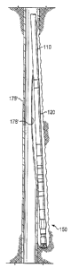
[0029] Refernng now to FIGURE l, one exemplary embodiment of a downhole tool
100 according to the present invention is illustrated. In FIGURE l, downhole
tool 100 is
illustrated as a measurement while drilling (MWD) tool including upper 110 and
lower
120 sensor sets coupled to a bottom hole assembly (BHA) 150 including, for
example, a
steering tool 154.and a drill bit assembly 158. The upper 110 and lower 120
sensor sets
_, _ are disposed-at a known,spacing,,ty~ical~r_on the order of about 10 to
20,meters_~i.e., ____ _
about 30 to 60 feet}. Each sensor set (110 and 120) includes at least two
mutually
perpendicular gravity sensors, with at least one gravity sensor in each set
having a known
orientation with respect to the borehole.
[0030] Referring now to FIGURE 2, a diagrammatic representation of a portion
of the
MWD tool of FIGURE 1 is illustrated. In the embodiment shown on FIGURES l and
2,
each sensor set includes three mutually perpendicular gravity .sensors, one of
which is
oriented substantially parallel with the borehole and measures gravity vectors
denoted as
Gzl and Gz2 for the upper and lower sensor sets, respectively. The upper 110
and lower
120 sensor sets are linked by a structure 140 (e.g., a semi-rigid tube such as
a portion of a
drill string) that permits bending along its longitudinal axis ,50, but
substantially resists
rotation between the upper 110 and lower 120 sensor sets along the
longitudinal axis 50.
Each set of gravity sensors thus may be considered as determining a plane (Gx
and Gy)
and pole (Gz) as shown. The structure 140 between the upper 110 and lower 120
sensor
sets may advantageously be part of, for example, a MWD tool as shown above in
FIGURE 1. Alternatively, structure 140 may be a part of substantially any
other logging
and/surveying apparatuses, such as a wireline surveying tool.
CA 02458254 2004-02-18
11
[00311 Referring now to FIGURE 3, the lower sensor set 120 has been moved with
respect to upper sensor set 110 (by bending structure 140) resulting in a
change in
azimuth denoted 'delta-azimuth' in the figure. The following equations show
how the
foregoing methodology may be achieved. Note that this analysis assumes that
the upper
I IO and lower 120 sensor sets are rotationally fixed relative to one another.
[U032] The borehole inclination (Incl and Inc2) may be described at the upper
110 and
lower 120 sensor sets, respectively, as follows:- _ . , . __. ,_ ._~ _ , _. .
_ __ .
Gxl2 + Gylz
Incl = arctan( ~1 ) Equation 1
Inc2 = arctan( Gx ~ 2Gy2z ) Equation 2
where G represents a gravity sensor measurement (such as, fox example, a
gravity
vector measurement), x, y, and z refer to alignment along the x, y, and z
axes,
respectively, and I and 2 refer to the upper 110 and lower 120 sensor sets,
respectively.
Thus, for example, Gxl is a gravity sensor measurement aligned along the x-
axis taken
with the upper sensor set 110. The artisan of ordinary skill will readily
recognize that the
gravity measurements may be represented in unit vector form, and hence, Gxl,
Gyl, etc.,
represent directional components thereof.
[0033] The borehole azimuth at the lower sensor set 120 may be described as
follows:
BoreholeAzimuth = ReferenceAzimuth + DeltaAzimuth Equation 3
where the reference azimuth is the azimuth value at the upper sensor set I 10
and
where:
DeltaAzimuth = Beta Equation 4
1- Sin((Incl.+ Inc2) l 2)
CA 02458254 2004-02-18
12
and:
Beta = arctan( (Gx2 * Gyl - Gy2 * Gxl) * Gxl Z + Gyl2 + C'rzl ~ ) Equation 5
Gz2*(Gxlz +Gylz)+Gzl*(Gx2*Gxl+Gy2*Gyl)
In other embodiments, Equation 4 may alternatively be expressed as follows:
DeltaAzimuth = -Beta 1 + Incl Equation 4A.
* ~ .r~~z~
[0034] Using the above relationships, a surveying methodology may be
established, in
which first and second gravity sensor sets (e.g., accelerometer sets) are
disposed, for
example, in a drill string. As noted above, surveying in this way is known to
be
serviceable and has been disclosed in the '119 patent. In order to utilize
this
methodology, however, a directional tie-in, i.e., an azimuthal reference, is
required at the
start of a survey. The subsequent surveys are then chain referenced to the tie-
in
reference. For example, if a new survey point (also referred to herein as a
survey station)
has a delta azimuth of 2.51 degrees, it is conventionally added to the
previous survey
point (e.g., 183.40 degrees) to give a new azimuth (i.e., borehole azimuth) of
185.91
degrees. A subsequent survey point having a delta azimuth of 1.17 degrees is
again
added to the previous survey point giving a new azimuth of 187.08 degrees.
[0035) If a new survey point is not exactly the separation distance between
the two
sensor packages plus the depth of the previous survey point, the prior art
recognizes that
extrapolation or interpolation may be used to determine the reference azimuth.
However,
extrapolation and interpolation techniques risk the introduction of error to
the surveying
results. These errors may become significant when long reference chains are
required.
Thus it is generally preferred to survey at intervals equal to the separation
distance
between the sensor sets, which tends to increase the time and expense required
to perform
CA 02458254 2004-02-18
13
a reliable survey, especially when the separation distance is relatively small
(e.g., about
. 30 feet). It is therefore desirable to enhance the downhoIe surveying
technique described
above with supplemental referencing, thereby reducing (potentially eliminating
for some
applications) the need for tie-in referencing. .
[0036] Aspects of the present invention provide a method for utilizing
supplemental
reference data in borehole surveying applications. The supplemental reference
data may
. be in substantially any- suitable ; form, e.g.,. as provided" b~! one or
more magnetometers . .
andlor gyroscopes. With continued reference to FICrURES 2 and 3, in one
embodiment,
the supplemental reference data are in the form of supplemental magnetometer
measurements obtained at the upper sensor set 110. The reference azimuth value
at the
upper sensor set 110, may be represented mathematically, utilizing the
supplemental
magnetometer data, as follows:
(Gxl * Byl - Gyl * Bxl) * Gxl2'+ Gyl2 + GzI2
RefeYenceAzirnuth = arctan( ) Equation 6
Bzl * {GxlZ + Gyl2 } - Gzl * (Gxl * Bxl - Gyl * Byl)
where Bxl, Byl, and Bzl represent the measured magnetic field readings in the
x, y, and
z directions, respectively, at the upper sensor set 110 (e.g., via
magnetometer readings).
The borehole azimuth at the lower sensor set 120 may thus be represented as
follows:
(Gxl * Byl - Gyl * Bxl) * Gxl2 + Gyl2 + Gzl2
BoreholeAzimuth = arctan( ) +...
Bzl * (Gxlz + Gyl2} - Gzl * (Gxl * Bxl - Gyl * Byl)
Beta
~~ ~ 1- Sin((Ihcl + fnc2) l 2) ~ Equation 7
CA 02458254 2004-02-18
14
where Beta is given by Equation 5 and inci and Inc2 are given by Equations 1
and 2,
respectively, as described previously. Also as described . previously, in
other
embodiments, Equation 7 may also be expressed as follows:
BoreholeAzirrcuth = arctan( (Gxl * Byl - Gyl * Bxl) * Gxl2 + Gyh + Gzl2 ) +
.'.
Bzl * (Gxl2 + Gyl Z ) - Gz1 * (Gxl * Bxl - Gyl * Byl)
. . . - Beta * Cl + Incl ~ Eq~,hon 7A
Inc2
jQ037] It will he..apprecia.~d_that_the..~hova arrangement in..which the.upper-
sensor .set
IV10 (FIGURES 1 through 3) includes a set of magnetometers is 'merely
exemplary.
Magnetometer sets may likewise be disposed at the lower sensor set 120. For
some
applications, ~ as described in more -detail below, it may be advantageous to
utilize
magnetometer measurements at both the upper 110 and lower 120 sensor sets.
Gyroscopes, or other direction sensing devices, may also be utilized to obtain
supplemental reference data at either the upper I 10 ar lower 120 sensor sets.
[4U38] It will also be appreciated that the above discussion relates to the
generalized
case in which each sensor set provides three gravity vector measurements,
i.e., in the x, y,
and z directions. However, it will also be appreciated that it is possible to
take only two
gravity vector measurements, such as, for example, in the x and y directions
only, and to
solve for the third vector using existing knowledge of the total gravitational
field in the
area. The unknown third gravity vector may be expressed as follows:
G = Gz_G~a-G z
Equation 8
[0039] . where G3 is the unknown third gravity vector, G is the known local
total
gravitational vector, and GI and G2 are the gravity vectors measured by the
two gravity
sensors in each sensor set (e.g., oriented in the x and y directions). The
third gravity
CA 02458254 2004-02-18
vector, G3, may then be used, along with the frst two gravity vectors, Gl and
G2, in
equations 1 through 7 to solve for the borehole azimuth and inclination as
described
previously.
[0040] ~ Likewise, in the absence of magnetic interference, it is possible to
take only two
magnetic field measurements and to solve for the third using existing
knowledge of the
total magnetic field in the area. The unknown third magnetic field vector may
be
_ .. expressed as follows: .. . ._._. . . ._.. . _.. ._ ..._. . ..__.._.~..
.... __.
B3 = Bz _Biz _Biz
Equation 9
(0041] where B3 is the unknown third magnetic field vector, B is the known
local total
magnetic field vector, and B 1 and B2 are the magnetic field vectors measured
by the two
magnetic field measurement sensors in each sensor set (e.g., oriented in the x
and y
directions). The third magnetic field vector, B3, may then be used, along with
the first
two magnetic field vectors, B 1 and B2, in equations 6 and 7 to solve for the
borehole
azimuth as described previously.
[0042] The artisan of ordinary skill will readily recognize that Equations 8
and 9 result
in a positive solution for G3 and B3, respectively. Thus, additional
information is
typically required in order to accurately determine the sign (positive or
negative) of the
unknown vector. For example, 'when Gz is the unknown gravity vector, knowledge
of the
vertical orientation of the tools may be required, e.g., whether a drilling
tool is drilling
downward (positive z) or upward (negative z). . alternatively, a survey tool
may be
rotated in the borehole and surveys taken at two or more rotational
orientations. For most
applications it is preferable to utilize three mutually orthogonal sensors and
to measure
each of the three gravity andlor magnetic field vectors. Nevertheless, in
operation,
... _.___ _ . .......uw. .~~...r~.~.~. .~..~"~ . ,~n,a. ~w---. ---.-....-~--
~..Mw"~~~~,~~~"~--:-~.~-..~~ ~__A ___..__~_ _._~_._..._.___~___
CA 02458254 2004-02-18
16
situations may arise (such as a failed sensor) in which the use of Equations 8
and/or 9 are
useful in the solution of an unknown gravity or magnetic field vector.
{0043] The following examples are provided to illustrate exemplary advantages
of the
surveying methodology of the present invention, utilizing supplemental
reference data,
for example, in the form of supplemental magnetometer measurements.
{0044] Referring now to Table l, a portion of an exemplary survey conducted at
a
measured ,depth. ranging from, about 10,600 to about __1,1,300 feet is
illustrated._ In this ,..
example, a prior survey, conducted according to the.method disclosed in the
'119 patent,
is further referenced to supplemental reference azimuths derived via magnetic
field
measurements. Survey points 1 through 9 are conducted according to the method
of the
' 119 patent, and thus the measured azimuth values at a given survey point are
referenced
back to the azimuth value of the previous survey point (e.g., the reference
azimuth for the
second survey point is the azimuth for the first survey point, 189.45
degrees). Survey
points 10 through 16, on the other hand, are conducted according to exemplary
embodiments of the present invention and as described above utilized
supplemental
reference azimuths derived from magnetometer readings.
Survey DepthInclinationAzimuthGravity Magnetic
Point (ft) (de ees degrees)ReferenceReference
105 2.7 89.45 .80
1 5 1 189
99
_ _ _ _
_ _ 189.38 189.45
2 10632 2.80
3 10665 2.87 189.98 189.38
4 10698 2.90 189.71 189.98
5 10731 2.95 189.88 189.71
6 10764 2.80 190.64 189.88
7 10?97 2.80 290.36 190.64
8 10828 2.89 189.73 190.36
9 2.87 193.37 189.73
10863
_ 3.00 199.94 196:14
10 ~ 10902
CA 02458254 2004-02-18
17
11 109293.26 203.79 201.71
12 109623.56 204.56 203.28
13 110094.62 210.10 207.37
14 111046.23 223.30 219.83
15 111997.74 238.05 234.14
16 112949.33 254.65 250.54
Table 1
[flfl45j Survey points 1 through 9 are conducted at depth intervals of
approximately 33
feet, which corresponds with the spacing between the first and second sensor
sets along ,
the drill string. Note, however, that survey points l3 through l6
are~conducted at depth
intervals of about 95 feet, thus highlighting one advantage of this invention.
Since the
reference azimuth is determined directly (see Equation 6) at the surveying
tool, a survey
may be taken at substantially any location, absent magnetic interference
effects in the
borehole. Surveying in such a manner advantageously reduces the number of
required
survey points, which typically results in significant time and cost savings.
It should also
be noted that embodiments of this invention substantially eliminate azimuth
errors
associated with chain referencing back to a tie-in reference. Note that the
supplemental
reference azimuth of survey point 10 is about 2.77 degrees greater than
(196.14 minus
193.37) the measured azimuth of survey point 9. The use of the supplemental
reference
data eliminates this source of error since the magnetically derived reference
azimuth is
"real time", i.e., independent of historical surveys.
[0046] The magnetically derived supplemental reference (i.e., that obtained at
survey
point 10 in Table I) may also be applied retrospectively to the earlier survey
points to
remove the reference error (about 2.7 degrees in the example of Table 1). The
results of
this retrospective correction are shown in Table 2.
Survey Depth Inclination Azimuth Gravity Magnetic
Point , (ft) ~ (degrees) ~ (degrees) ~ Reference ~ Reference
CA 02458254 2004-02-18
18
1 105992.75 192.15 192.50
2 106322.80 192.08 192.15
3 106652.87 192.68 192.08
4 106982,90 192.41 192.68
5 107312.95 192.58 192.41
6 107642,80 193.34 192.58
7 107972.80 193.06 193.34 .
8 108282.89 192.43 193.06
9 108632.87 196.07 192.43
10 109023.00 199.94 196.14
I1 109293.26 203.79 201.71
12 109623.56 204.56 _
I3 I . -4.62 21(3.10 203.28
14 1009 6.23 . 2p7~7-
11104 223.30 219.83
1S 111997.74 238.05 234.14
16 112949.33 254.65 250.54
Table 2
[0047j The resultant end of the line borehole position at survey point 16
(Tables l and
2) is shown in Table 3. The position is shown in "world" coordinates as
determined
without supplemental referencing (i.e., using the gravity azimuth technique as
described
in the '119 patent), with supplemental referencing, and with supplemental
referencing and
retrospective correction. Note that use of embodiments of the supplemental
referencing
aspect'of this invention results in a significant correction in the final
surveyed position of
the borehole, with the true position (as determined using supplemental
referencing) Iying
about 11 feet north and 4 feet east of that determined using the conventional
gravity
surveying methodology described'in the '119 patent.
East/West North/SouthTotal Vertical
ft) (ft) De th (ft)
Without supplemental referencing _7,53-157.01 7495.1
With supplemental referencing _3.25 -146.33 7495.1
With supplemental referencing and _3,g4-146.19 7495.1
CA 02458254 2004-02-18
' ~ '
19
retrospective correction
Table 3
[0048] Referring now to FIGURE 4, the exemplary embodiment of the present
invention shown in FIGURE 1 is -shown deployed in a system for kicking off out
of the
casing shoe 177 of a pre-existing borehole. "Kicking off' refers to a quick
change in the
angle of a borehole, and may be associated, for example with drilling a new
hole from the
bottom or the side of an existing borehole. As shown, the bottom hole assembly
I50 has
lienetrated the casing shoe 177. The upper 110 and lower 120 sensor sets
remain in the
casing 175 of the existing borehole, and emexge therefrom after further
drilling. As
described in more detail in the example provided below, in embodiments
including
magnetic sensors, the surveys in the vicinity of the casing shoe 177 may
employ
conventional gravity surveying methods, thereby chain referencing the azimuth
values of
the surveyed points to a tie-iri reference point located in the existing
borehole. When the
magnetic sensors, e.g., at sensor set 110, are substantially free of the
magnetic
interference from the casing 175 and casing shoe 177, surveys utilizing
supplemental
referencing may be taken according to the present invention at any position,
e.g., at about
30 meter (about 98 feet) intervals, and are independent of surveys taken
previously or at
any time. As described .above, this reduces reliance on "chain" surveys, as
well as
reducing the number of surveys required, while still maintaining the
directional
information from positions down to a very low position in the BHA -- possibly
as low as
in the drill bit.
[0049] Refernng now to FIGURE S, the exemplary embodiment of the present
invention shown in FIGURE I is shown deployed in a system for kicking off out
of a
casing window I78' of a pre-existing borehole. Drilling out of a casing window
178' is
CA 02458254 2004-02-18
similar to drilling out of a casing shoe 177 (FIGURE 4) with respect to the
inventive
surveying techniques disclosed herein. In both instances there tends to be
magnetic
interference after the sensox packages move out of the casing 175, 175'.
Normally the
magnetic interference fades more quickly when drilling out of a casing shoe
177 since the
distance to the casing 175, 175' increases more rapidly than during drilling
out of a casing
window 178'. Advantageous deployments of the present invention in penetrating
a
casing window are substantially analogous to that of penetrating a casing
shoe, e.g., as
described above with respect to FIGURE 4.
[0050] Referring now to FIGURE 6, the exemplary embodiment of the present
invention shown in FIGURE 1 is shown deployed in a relief well drilling and/or
a well
avoidance application. Adjacent wells (e.g., shown as casing 175" in FIGURE 6)
are
known to generate magnetic interference, which tends to intezrupt compass-
based
azimuth surveys in the borehole being drilled. Surveying according to the
present
invention may be useful in such applications. Advantageously, alternative
systems, such
as wire line gyroscopes, may be obviated.
[0051] Additionally, during the drilling of relief wells, or in well
avoidance, it is
generally desirable to know the position of the adjacent well to reduce the
risk of collision
andlor to place the well into the kill zone (e.g., near a well blow out where
formation fluid
is escaping to an adjacent well). The magnetic techniques used to sense the
adjacent
borehole position may generally be subdivided into two main groups -- active
ranging and
passive ranging.
[0052] In active ranging, an artificial magnetic field is induced into the
local
subterranean environment. The properties of this field are assumed to vary in
a known
CA 02458254 2004-02-18
21
manner with distance and direction away from the source and thus may be used
to
determine the location of neaxby magnetic subterranean structures.
[0053] In contrast, passive ranging, such as disclosed in U.S. Patent
5,675,488
(hereafter referred to as the '488 patent), and as described in more detail
below, uses the
natural magnetic field emanating from magnetic components within the adjacent
borehale
(e.g., the casing). As described below, passive ranging techniques generally
make no
assumptions about the magnetic field strength or the relative magnetic pole
positions
~.vithin the adjacent borehole.
[0054] Both active and passive ranging techniques typically require
inclination and/or
azimuth data from the borehole being drilled. Thus, as described further
hereinbelow,
aspects of the present invention may advantageously enhance the performance of
both
active and passive ranging.
[0055] Referring now to FIGURE 7, a portion of an exemplary survey conducted
at a
measured depth ranging from about 2,200 to about 5,000 feet is described. A
MWD tool
deployment similar to~ that described above with respect to FIGURE 1 was
utilized. The
upper and lower sensor sets each included three mutually perpendicular
magnetometers
and three mutually perpendicular accelerometers. However, only the
magnetometer data
from the upper sensor set was utilized in this example. The lower sensor set
was disposed
about 54 feet below the upper sensor set. FIGURE 7 is a graphical
representation 200 of
azimuth on the ordinate axis 202 versus well depth on the abscissa axis 204
for a portion
of a casing window kick-off operation (see, for example, FIGURE 5). The
azimuth
values of the preexisting well, as determined by a conventional gyroscope
survey, are
shown at 2I2. The azimuth values determined from the gravity measurements
(using the
techniques described above) are shown at 214, while azimuth values determined
using the
CA 02458254 2004-02-18
).
22
magnetic field. measurements are shown at 216. The azimuth values determined
from the
gravity and magnetic field measurements are also shown in tabular form in
Table 4
below.
[0056] With continued reference to FIGURE 7 and Table 4, the survey of this
example
was tied-in to the gyroscope survey of the preexisting borehole at 232 (survey
point 0 in
Table 4). In region 222 (survey points 1 through 5) the upper and lower sensor
sets (e.g.,
sensor sets 110 and 120 in FIGURE 1) were disposed in the casing of the
preexisting
borehole. Hence, owing to the magnetic interference emanating from the casing,
the
azimuth values determined from the magnetic field ' measurements were rendered
unreliable (as shown in Table 4). The azimuth values were thus chain
referenced back to
the tie-in reference point 232 using the methodology described above. Region
222 is
described in further detail below with respect to FIGURE 8 and Tables 5 and 6.
[0057] With further reference to FIGURE 7 and Table 4, the lower sensor set
penetrated the casing of the preexisting borehole at point 234 (survey point 6
in Table 4).
The azimuth values determined from the magnetic field measurements remained
generally unreliable in region 224 (survey points 6 through 15) as the upper
sensor set
moved away from the casing of the preexisting borehole, but remained within a
magnetic
interference region. Thus the azimuth values were chain referenced back to the
tie-in
reference point 232. As a result, survey points were taken- at approximately
54 foot
intervals (the vertical spacing between the upper and lower sensor sets).
Beginning at a
measured depth of approximately 3000 feet, the upper sensor set was
sufficiently free
from magnetic interference for highly effective use of supplemental
referencing of the
azimuth values. Thus in region 22b (survey points 16 through 41 in Table 4),
the survey
points were taken according to the supplemental referencing aspect of the
present
CA 02458254 2004-02-18
/.. ,
23
invention as described above. Note that the survey interval at survey points
20 through
41 was increased from about 54 to about 94 feet, representing a significant
savings in
time and cost.
SurveyDepthMagnetic AzimuthDepthGravity AzimuthDelta Azimuth
Point (ft) de ees) (ft) (de ees) (de ees)
0 2262 91.90
_ _ _ _
1 2262 291 .55 2316 __ -0.73
~ 91.1
7
_ _
2 2312 3.3_9..93.._ .2366__ _ -3 Z6
87,71
3 2364 292.86 2418 86.08 -1.70
4 2417 20.08 2471 88.79 2.78
5 2465 39.86 2519 92.37 4.04
6 2548 59.98 2602 ~ 98.59 4.06
7 2605 263.43 2659 .88 1
99 .22
8 2656 ____ 2710 _ __
76.62 _ _
_ _ 3.18
102.87
9 2697 95.14 2751 105.73 3.78
IO 2743 124.42 2797 109.04 3.91
I1 2791 163.24 2845 111.57 2.85
I2 2844 107.02 2898 112.10 0.54
13 2885 116:53 2939 111.81 -0.38
I4 2931 112.22 2985 113.27 1.72
15 2980 I14.S6 3034 116.51 3.58
16 3027 117.99 3081 120.65 2.66
17 3073 123:17 3127 124.33 1.16
18 3123 123.94 3177 125.26 1.32
19 3167 _ 3221 126.84 1.04
125.79
20 3261 126.9? 3315 130.33 3.36
21 3354 132.49 3408 138.13 5.64
22 3446 142.92 3500 148.69 5.77
23 3539 153.26 3593 157.65 4.39
24 3631 163.98 3685 168.95 4.97
25 3725 174.33 3779 179.36 5.03
26 3818 185.90 3872 192.31 6.41
27 3910 197.32 3964 201.11 3.78
28 4004 208.29 4058 208.94 0.66
29 40_97207.96 4151 208.55 0.60
30 4191 208.98 4245 209.02 ~ 0.04
31 4284 210.55 4338 210.68 0.13
32 4377 208.67 4431 205.98 -2.69
33 4469 205.75 4523 205.25 -0.50
34 4469 206.55 4523 205.67 -0.89
35 _ ~ 205.05 4523 204.36 -0.68
L4469
CA 02458254 2004-02-18
24
36 4563 203.99 4617 200.04 -3.95
37 4657 196.09 4711 195.53 -0.56
38 4750 195.81 4804 195.72 -0.09
39 4843 196.44 4897 199.44 3.00
40 4937 200.50 4991 203.22 2.71
41 50b0 205.33 5054 205.94 0.61
Table 4
[0058j Typically supplemental referencing may be highly efficacious even in
the
presence of low-level magnetic interference. As .described above, and shown in
the
previous example, at higher levels of magnetic interference the azimuth values
determined from the magnetic field measurements are not optimum and may be
unreliable
(depending upon the magnitude of the magnetic interference). It may thus be
advantageous in certain applications to ~ utilize a predetermined magnetic
interference
threshold to determine when the magnetic field measurements are sufficiently
free from
magnetic interference far the effective use ~of supplemental referencing. In
such a set-up,
supplemental referencing might be utilized at survey points having magnetic
interference
values less than the threshold, and chain referencing might be utilized at
survey points
having magnetic interference values greater than the threshold. In such a
manner, both
supplemental referencing and chain referencing might be utilized in one
survey. At the
onset of sufficiently high magnetic interference (e.g., above the threshold),
the
supplemental referencing might be turned off in favor of conventional chain
referencing
(e.g., back to a survey point having sufficiently low magnetic interference).
As drilling
progresses and the magnetic interference decreases, (e.g., below the
threshold) the
supplemental referencing may be fumed on, thereby eliminating the need for
chain
referencing in that region of the borehole. Further, the azimuth values
determined in the
CA 02458254 2004-02-18
sections of the borehole utilizing chain referencing may optionally be
retrospectively
corrected (e.g., from below) using the supplemental reference azimuth values.
[0059] The artisan of ordinary skill will readily recognize that referencing
the azimuth
to a sensor set including magnetometers in the absence of magnetic
interference is
substantially equivalent to referencing to a sensor set including a north
seeking or inertial
gyroscope. In methods utilizing a'gyroscope reference, the gyro is typically
capable of
determining a reference azimuth, which may be used in a similar manner to that
described
~.bove by other sensor set(s), possibly containing accelerometers only fox the
puxpose of
giving independent azimuths low in the BHA. A circumstance where this may be
desirable would be when movement may be affecting gyro surveys, as North
seeking
generally requires a gyro to be stationary for a few minutes. By deriving
another azimuth
with the accelerometers, the number of gyro surveys maybe greatly reduced and
the
gravity results may help determine the quality and accuracy of the gyxo
surveys.
[0060] Referencing to a magnetometer package or gyro within the same system
means
an increase in accuracy of the combined surveys may be obtained. Enhancing
with
supplemental reference data per the present invention provides the opportunity
for an
increase in the overall certainty/accuracy/quality of the combined
measurements. The
potential increase in measurement precision will be seen to be particularly
advantageous
in embodiments where gravity systems have double or even triple measurements
from the
same or different derivations and sensors.
[0061] As described above with respect to Equation 3, the borehole azimuth at
a given
survey point is equal to the sum of a reference azimuth and the change in
azimuth
between the two gravity sensor sets. The supplemental referencing aspect of
this
invention, as described above, advantageously enhances the accuracy of the
borehole
CA 02458254 2004-02-18
26
azimuth value by enhancing the accuracy of the reference azimuth. Supplemental
referencing, however, is not necessarily advantageous in improving the
accuracy of the
measured change in azimuth between the sensor sets. Thus it may also be
desirable, or
even required for some applications, to correct for causes that result in
significant errors
to the measured change in azimuth. One such potential source of error is
rotational offset
between the gravity sensor sets (i.e., misalignment between the x and y axes
of the sensor
sets). If the two sets of gravity sensors .are not rotationally aligned, it
may be possible to
iiieasure the rotational offset between them as an angular displacement, for
example, by
measuring the orientation of each set as it is lowered into the borehole. - It
will be
appreciated that once identified and measured or calculated, any offset may
then be
corrected for.
[0062] However, in some applications, it may be highly advantageous to be able
to do
any accounting for rotational offset downhoIe as well as topside. Thus,
according to
another aspect of this invention, the rotational offset (also referred to as
Re) may be
determined and corrected for if three or more azimuth values from a section of
the
borehale are previously known, for example, from a previous gyroscope survey.
Azimuth
values are , determined at three or more (preferably five or more) points
along the
previously surveyed portion of the borehole. The measured azimuth values are
then
compared with the known azimuth values. The rotational offset is varied until
the
measured azimuth values substantially match and/or fit the known azimuth
values.
[0063] Referring now to Tables 5 and 6, an example is provided to illustrate
one
exemplary approach for determining the rotational offset between the upper and
lower
gravity sensor sets (e.g., accelerometer sets}. The example described below is
taken from
the same survey as described above with respect to FIGURE 7. As described
above, a
CA 02458254 2004-02-18
27
previously drilled borehole was surveyed using a gyroscope. Azimuth values as
a
function of well depth are shown in Table 5 for a three hundred foot section
of the well
(approximately region 222 on FIGURE 7). At a measured depth of about 2262
feet, the
lower accelerometer set was referenced (i.e., tied-iri) to the azimuth value
(91.90 degrees)
from the previous gyroscopic survey taken at that depth. As described above
with respect
to FIGURE 7 and Table 4, the upper sensor set was positioned approximately 54
feet
above the lower sensor set. Hence, subsequent gravity surveys were conducted
at about
S4 'foot intervals over approximately a three hundred foot section of the
borehole.
Azimuth values were then calculated assuming various rotational offset values
as shown
in Table 5. In order to calculate the azimuth values, the gravity sensor
measurements
Gx2 and Gy2 were corrected for the rotational offset using well known
trigonometric
techniques. Exemplary equations used to determine the corrected Gx2 and Gy2
values
from the measured Gx2 and Gy2 values are given below as Equations IO and 1 I .
Gx2corr~ected = sin(arctan( Gx~) + Rc) (Gx22 + Gy2z Equation 10
v
Gy2corrected = cos(arctan( Gx~) + Rc) (Gx22 + Gy2z Equation 11
Y
where Gx2corrected and Gy2corrected represent the corrected gravity vectors,
Gx2 and Gy2 represent the measured gravity vectors, and Rc represents the
rotational
offset between the upper and lower sensor sets. Gz2 remains unchanged.
[0064] Measured and corrected values are shown in.Table 6 for a rotational
offset of
267.7 degrees. The azimuth values were then calculated using the methodology
described
above with respect to Equations 3 through 5.
CA 02458254 2004-02-18
28
DepthGyro AzimuthGMWD Azimuth GMWD AzimuthGMWD Azimuth
(ft) (degrees) (degrees) (degrees) (degrees)
Rc=266.0 de Rc=267.7 Rc=269.0 de
rees de ees ees
2262 91.9 91.90* 91.90* 91.90* .
2316 92.45 91.17 90.20
2362 87.4
2366 90.17 87.71 85.82
2418 89.80 86.08 83.23
2462 88.0
24'71 93.83 88.79 84.93
2519 98.61 92.37 87.60
2563 94.8
Table S
__,. ...._ ~ _.._... ~~ _..~~..~~,~-~.~.~~x.x,..z.a.,....~ ~~.. ~.~~. ~
_~.,.~._._.... -------_
CA 02458254 2004-02-18
29
Depth Gyro AzimuthGMWD Azimuth Gx2, Gy2 Gx2, Gy2
(ft) (degrees) (degrees) Measured Corrected
Rc=267.7 degrees Rc=267.7
2262 91.9 91.90
2316 91.17 -0.170, -0.225,
0.232 -0.179
2362 ~ 87.4
2366 87.71 -0.241, -0.165,
0.175 -0.248
2418 86.08 -0.151, 0.274, -0.140
-0.269
2462 88.0
2471 x$_79__- -Q.19,~, 0:26
- .?, -0~~85
60
0.2
2519 92.37 _ _
~ _ _
( -0.180, 0.284, -0.168
-0.277
63 94.8 _ _
Table 6
[0065] The azimuth-depth profiles may be matched using substantially any
technique
including known graphical and numerical methods. For example, with reference
to
FIGURE 8, a graphical representation 300 of azimuth on the ordinate axis 302
versus
well depth on the abscissa axis 304 is shown. The previous gyroscopic survey
is shown
at 310. The azimuth values at rotational offset values of 266.0, 267.7, and
269 degrees,
for example, are shown at 312, 314, and 316, respectively. A best fit is
indicated at a
rotational offset of approximately 267.7 degrees (see also Table 5). - As
stated above,
numerical methods, including, for example, least squares techniques that
iterate the
rotational offset, may readily be used to determine the best fit between the
previously
determined azimuth values and those determined in the gravity survey.
Alternatively, the
rotational offset may be determined. using known graphical methods, for
example, in a
spread sheet software package, and the rotational offset values manually
iterated until a
graphical "best-fit" is achieved. It will be understood that determination of
a suitable fit
is not limited to plots of azimuth versus well depth, such as that shown on
FIGURE 8.
Rather, any view of the azimuth values suitable for comparing the previously
measured
CA 02458254 2004-02-18
(known) and as measured azimuth values may be utilized. For example, in some
applications it may be advantageous to plot the azimuth values on a plan view.
Additionally; various data filtering techniques may be utilized to xeduce
noise in the
measured azimuth values, as is often observed,in wells having a near vertical
inclination.
For example, minimum curvature calculations may be utilized in conjunction
with a plan
view to constrain the azimuth values to a range of values consistent with
known
achievable borehale profiles.
[6066] Optimal precision in determining the rotational offset is typically
achieved in
borehole sections that are near vertical since the sensitivity of the
conventional gravity
azimuth techniques (i.e., as disclosed in the '119 patent) is greatest in such
near vertical
wells (e.g., wells having an inclination of less than about 10 degrees).
However, at
extremely low inclinations (e.g., less than about 1 degree) azimuth values are
well known
to be inherently unreliable {since the horizontal component of the borehole is
insignificant
as compared to the vertical component). Thus for many applications it may be
desirable
to determine the rotational offset of the accelerometer sets in a well section
having an
inclination value in the range from about 1 to about 10 degrees.
[0067] The approach described above for determining the rotational offset
between the
upper and lower accelerometer sets also advantageously provides an error
reduction
scheme that corrects for other systemic errors in addition to the rotational
offset.
Utilization of the above-described approach advantageously corrects for
substantially all
azimuthal misalignment errors between the accelerometer sets. One example of
such a
misalignment includes off axis positioning of the accelerometers in, for
example, a drill
string.
CA 02458254 2004-02-18
31
[oa6s] As described above, the supplemental referencing aspect of this
invention may
be effectively practiced utilizing supplemental magnetic field measurements
taken, for
example, from magnetometers disposed with one or both of the gravity sensor
sets. Also,
as described above, the supplemental referencing aspect of this invention may
be highly
effective in determining azimuth values even in the presence of low-level
magnetic
interference, but tends not to be optimum at higher levels of magnetic
interference.
Nevertheless, a supplemental referencing set-up utilizing supplemental
magnetic field
measurements may be particularly advantageous in that it may be used in
conjunction
with methods disclosed in U.S. Patent 5,675,488, for example, in well
avoidance and/or
subterranean structure location applications, even when the magnetic
interference levels
are sufficiently high so as to not be advantageous for azimuth determination.
Such
passive ranging utilizes the magnetic interference emanating from magnetic
subterranean
structures to advantageously determine their location, direction, andJor
orientation (i.e.,
inclination andlor azimuth) relative to the surveyed borehole.
[0069] In order to determine the magnetic interference vector at any point
downhole,
the magnetic field of the earth must be subtracted from the measured magnetic
field
vector. The magnetic field of the earth (including both magnitude and
direction
components) is typically known, for example, from previous geological survey
data.
However, for some applications may be advantageous to measure the magnetic
field in
real time on site at a location substantially free from magnetic interference,
e.g., at the
surface of the well or in a previously drilled well. Measurement of the
magnetic field in
real time is generally advantageous in that in that it accounts for time
dependent
variations in the earth's magnetic field, e.g., as caused by solar winds.
However, at
certain sites, such on an offshore drilling rig, measurement of the earth's
magnetic field in
CA 02458254 2004-02-18
32
real time may not be possible. In such instances, it may be preferable to
utilize previous
geological survey data in combination with suitable interpolation and/or
mathematical
modeling (i,e., computer modeling) routines. It is also necessary to know the
orientation
of the magnetometer sensors in the borehole being drilled, which may be
determined, for
example, by the surveying techniques described above.
[0070] The earth's magnetic field at the tool may be expressed as follows:
MEX =HE(cosDsinAzcosR+cosDcosAzcoslncsinR-sinDsinlncsinR)
MEY =HE(cosDcosAzcoslnccosR+sinDsinlnccosR-cosDsinAzsinR)
MEZ =HE{sinDcoslnc-cosDcos~zsinlnc) Equation 12
where Mex, Mey, and Mez represent the x, y, and z components, respectively, of
the
earth's magnetic field as measured at the down hole tool, where the z
component is
aligned with the borehole axis, He is known (or measured as described above)
and
represents the magnitude of the earth's magnetic field, and D, which is also
known (or
measured), represents the local magnetic dip. Inc, Az, and R, represent the
Inclination,
Azimuth and Rotation (also known as the gravity tool face), respectively, of
the tool and
are typically determined from gravity, magnetic, and/or gyroscope sensor
measurements
as described above. The magnetic interference vectors may then be represented
as
follows:
M~ = BX - M~
MIY '-'8Y MEY
Mrz = Bz - MEZ Equation 13
CA 02458254 2004-02-18
33
where Mix, Miy, and Miz represent the x, y, and z components, respectively, of
the magnetic interference vector and Bx, By, and Bz, as described above,
represent the
measured magnetic field vectors in the x, y, and z directions, respectively.
(OQ71] The artisan of ordinary skill will readily recognize that in
determining the
magnetic interference vectors it may also be necessary to subtract other
magnetic field
components, such as drill string and/or motor interference from the borehole
being
drilled, from the measured magnetic field vectors.
[0072) It should be noted that the magnetic interference may emanate from
substantially any point or points on a target well. It may also have
substantially any field
strength and be oriented at substantially any angle to the target well. It is
the particular
shape of the field, rather than its strength, that enables the source to be
located using the
method of this invention, which assumes, as described in more detail below,
that a target
well behaves substantially equivalently to one or more cylindrical magnets.
Thus it is
assumed herein that the shape of the magnetic flux lines is consistent with
having
emanated from a cylindrical magnet.
[Ofl73] The magnetic interference from the metal objects in an adjacent well
is typically
caused by the tubular elements therein, e.g., the casing, drill string,
collars, and the like.
The magnetic interference surrounding these elements is determined by the
magnetism
(both induced and permanent) in the metal. The shape of the interference
pattern is
particularly influenced by the homogeneity of the magnetism and the shape of
the metal
element. Typically, the magnetism is substantially homogeneous and the shape
rotationally symmetrical and tubular. Objects in a borehole, such as pipe
sections and the
like, are often threadably coupled to form a substantially continuous
cylinder. Thus, the
origin of any magnetic interference from a borehole may generally be
considered to
CA 02458254 2004-02-18
34
originate in cylinders in the target well, the magnetic field emanating from
such cylinders
in a manner typically displayed by cylindrical magnets. The field strength
decreases with
distance from the borehole. The magnetic interference may be measured as a
vector
whose orientation depends on the location of the measurement point within the
magnetic
field.
[0074] Referring now to FIGURE 9, the relationship between the path M of the
borehole being drilled (also referred to as the measurement Iine), the line of
an adjacent
target well T (also referred to as the target line or as an adjacent well or
borehole), and the
calculated interference vectors 401 through 407 measured at various points a
through g
along the path M are shown. Magnetic field lines 410 awing to the "cylindrical
magnets"
in the target well are also shown. As shown the measured interference vectors
401
through 407 are tangential to the field lines 410 at points a through g,
respectively. It
should be noted that it is not necessary to know the magnitude of the vectors.
Thus, in
this technique, each vector may be extended to a substantially infinite line
in three-
dimensional space.
[0075] Referring now to FIGURE 10, the path M of the borehole being drilled,
the
target borehole T, and the interference vectors 401 through 407 are shown
projected on a
plane substantially perpendicular to the target borehole T (i.e., the pole of
the plane is
along the target borehoIe T). The interference vectors 401 through 407 are
shown
extended as dotted lines. The interference -vectors 401 through 407 each
substantially
intersect the target borehole T, and thus appear to intersect at a point T in
FIGURE 10.
The direction and location of the target borehole T may therefore be
determined, as
described further below, by determining the plane perpendicular to the target
well.
___ ._.__ _ _. __._._ ___~......_..'a~""..~~,~.~~.~w,.....,s~~,,~ p~-~.---._ ~
___._~~.".~.-.~.~..._.,~ ~_._.--.- _.___~_..____
CA 02458254 2004-02-18
[0076] Referring now to FIGURE 11, a hypothetical exemplary drilling operation
is
shown, with the interference vectors typically measured at various points a'
through i'
along the measurement line M (i.e., the borehole being drilled). Lines 501
through 509
are the extended lines, which include the linear interference vectors. Lines
501 through
504 are extended from interference vectors measured at points a' through d',
respectively,
along the measurement line M. At these points there is no appreciable magnetic
interference from the target well T. The interference vectors 501 through 504
have been
corrected for the effects of the earth's magnetic field (as described above
with respect to
Equations 12 and 13) and are owing to, for example, interference from the
drill string in
the borehole being drilled, At point e' on the measurement line M,
interference from the
target well T is detected and the vector extended to Iine 505 is the result of
a combination
of drill string interference and interference from the adjacent well. As the
borehole being
drilled approaches the target well T the magnetic interference therefrom tends
to increase
as compared to the drill string interference. Lines 506 through 509 are
extended from
vectors that have been corrected for drill string interference and thus
essentially due only
to interference from the target well. As shown, each of lines 506 through 509
cross the
axis of the target well T, which is substantially perpendicular to the plane
of FIGURE I 1.
FIGURE 11 also shows the position X at which the target well T was thought to
be using
a gyro technique.
[0077] In a typical drilling operation, in which avoidance of a nearby
structure, for
example, is highly desirable or even required, the surveying techniques of
this invention
may be utilized to determine the inclination and azimuth of the measured well
during
drilling. At the indication of an outside source of magnetic interference,
e.g., two or more
survey points having a magnetic interference vector with a magnitude greater
than some
CA 02458254 2004-02-18
36
predetermined threshold, it may be appropriate to reverse the tool and take
additional
magnetometer readings. Such a procedure may enable analysis of the position of
the
source of interference to be determined so that corrective action (e.g., well
avoidance
procedures), if necessary, may be taken. At each survey point the azimuth and
inclination
of the borehole being drilled are typically determined, for example, using the
surveying
techniques described above. If the magnitude of magnetic interference from the
adjacent
borehole is sufficiently large, the azimuth values may need to be chain
referenced back to
a prior survey point at which substantially no magnetic interference was
present in order
to assure integrity of supplemental reference data provided by magnetometers.
The
component of the total magnetic field attributable to the outside interference
is then
determined at each survey point, as described above with respect to Equations
12 and 13.
The position of the interference vectors along the borehole for each survey
point may be
determined using the azimuth and inclination values taken from the survey in
conjunction
with any suitable method known to those skilled in the art, such as minimum
curvature,
radius of curvature, average angle techniques, ~ and the like.
(0078) In many applications, it is desirable to determine the inclination and
azimuth of
the target well T as well as the displacement D (the nearest distance) between
the
measured borehole and the target line T. If no information is available on the
spatial
location of the target well T, at least four vectors are generally required to
determine the
above factors. If one parameter of the target well T is known, e.g., azimuth,
generally
only three vectors are required. If the azimuth and inclination are already
known, a
solution of the displacement D may be found with only two vectors. In other
applications, the azimuth and inclination may be known within a range, for
example, it
may be known that the azimuth is in the range from about 200 to 240 degrees
and the
._......__.~.~ ~rwrv~ .M.....w~,,m,...~.......,~....~.,.~..,~.~"..~,~~~n.~.-..-
~.... _ _....._ ~.~..~ ~~,~~,~...~"~.".~--..~-T-_.- ---_~._~
CA 02458254 2004-02-18
37
inclination is in the range from about 5 to IS degrees. Such information does
not
typically reduce the number of vectors required but may significantly reduce
the time
required for a calculation of a solution for azimuth, inclination and
displacement of the -
target well by constraining the solution thereof.
[0079] Having determined the interference vectors and generates a set of
extended lines
therefrom, it is necessary to find the viewing plane at which the intersection
points of the
vectors (extended lines) substantially cross the target well T, as shown in
FIGURE -10.
t~s described below with respect to FIGURE 13, such a viewing plane is
typically
selected to be one in which the distance between the intersection points and
the target
well is at a minimum. Such a viewing plane as describe above is substantially
orthogonal
to the target well (i.e., having a pole along the target well). Determination
of the viewing
plane may be accomplished by utilizing a three dimensional CAD package and
changing
the viewing angle or viewing plane interactively to find the plane at which
the vectors (or
extended lines) appear to substantially cross. However, it is typically
desirable to
determine the plane mathematically, for example, by converting the vectors
into linear
equations and using conventional techniques such as a least squares technique
(or other
technique such as spline fitting and the like).
[0080] In one approach, the magnetic interference vectors given in Equation 13
are
transformed into azimuth, magnetic dip, and magnitude coordinates as given
below:
Azi =arctan( G(MlxGy-MnGx) )
M~GxGz+M~,GyGz+M~(Gxz +Gy2)
Dipl = arctan( MrY
MIYZ +MIY2 +M~2 +(M~Gx+MIYGy-M,zGz)lG
M~ = M~2 +Mn2 +M,~Z Equation I4
CA 02458254 2004-02-18
38
where Azii, Dipi, and MI are the azimuth, dip and magnitude, respectively, of
the
interference vectors.
(0081] The vectors are then rotated in an iterative fashion in both a
horizontal plane
(e.g., about the z-axis in "world" coordinates) and a vertical plane (e.g.,
about either the
x- or y-axes in "world" coordinates) by adding angle increments to the azimuth
and dip
values, respectively, given in Equation 14. At each rotational increment, the
interference
vectors are projected onto a two-dimensional view acrd _ the distances between
the
intersection points of the various extended interference vectors are
calculated. Such a
rotational iteration is continued until a two-dimensional view is found in
which .the
distances between the intersection points are substantially at a minimum
(e.g., the view on
FIGURE 10). As described above, the two-dimension view (i.e., the plane) at
which such
a minimum is found is taken to be substantially orthogonal to the target well.
The
location of the target well in such a two-dimensional view may be found, for
example, by
taking a mathematical average (or a weighted mathematical average) of the
locations of
the various intersection points. It will be understood that mathematical
techniques other
than averaging may be utilized to determine the location of the target well.
As described
above, the number of vectors utilized, and therefore the number of
intersection points,
depends on the analysis required. Typically three to five (or more)
interference vectors
are utilized resulting in three to ten (or more) intersection points between
the various
interference vectors.
[0082] Upon determining x and y coordinates of the target well (in the
coordinate
system of the two-dimensional view}, the location and orientation (i.e.,
inclination and
azimuth) of the target well (e.g., target well T in FIGURES 9 through 11) may
be
determined in either "world" coordinates or the coordinate system of the
measured
CA 02458254 2004-02-18
39
borehole using conventional mathematical techniques. The distance and the
direction
(referred to commonly as rotation or tool face) to the target well at each
surveyed point in
the measured well may be given, respectively, as:
Dn = (xT - xn)Z + (yT - yn)2 Equation 15
Rn = arctan( (xT - xn) ) Equation 16
(YT i Yn)
where n represents the individual survey points, e.g., 1, 2, 3, etc., xn and
yn are the x and
y°coordinates, respectively, of survey point n in the two-dimensional
view, and xT and yT
are the x and y coordinates of the target well in the two-dimensional view. It
will be
understood that xn, yn, xT, and yT are given in the coordinates system of the
two-
dimensional view described above (e.g., as shown in FIGURES 10 and 13). A
comparison of the distance to the adjacent well from one survey point to the
next provides
valuable information, for example, regarding whether the survey tool (e.g., in
a drilling
operation) in the measured well is moving towards or away from the target
well. The
rotation (tool face) is also advantageous to know in that it indicates the
direction that
drilling must commence in order to move towards (e.g., in a weh kill
operation) or away
from (e.g., in a well avoidance application) the target well.
[0083] The inclination and azimuth of the target well may be determined from.
the
angular orientation of the plane orthogonal to the target well. The
orientation of the plane
is known from the rotational iteration of the interference vectors about a
horizontal and
vertical plane, as described above. The angle to the horizontal plane
represents the
azimuth of the target well while the inclination of the target well may be
derived from the
angle to the vertical plane. Determining the inclination and azimuth of the
target well
may be useful in certain applications, in particular in a multi-well
environment in which
CA 02458254 2004-02-18
knowledge of the inclination and azimuth values may enable the target well to
be
identified based upon previous survey data.
j0084] In determining the location of the target well, it may be advantageous
in certain
applications to employ one or more techniques to minimize or eliminate the
effect of
erroneous, data. For example, one suitable technique that may be optionally
utilized is a
"maximum distance limit" that eliminates outlying intersections points that
are greater
than some predetermined distance threshold (e.g., 500 feet) from the survey
point. Such,
intersection points typically, although not necessarily, exceed the normal
range of passive
ranging, and thus may optionally be considered as erroneous. In some
applications, e.g.,
a well kill operation, in which the target well is known to be relatively
close to the
measured well, it may be reasonable to significantly reduce the "maximum
distance limit"
threshold, for example, to 100 feet or less. Alternatively and/or
additionally, it may be
advantageous to apply statistical methods to eliminate outlying intersection
points, for
example, removing intersection points that are greater than two standard
deviations away
from the above described mathematical average. In certain instances it may
also be
desirable to remove individual interference vectors from the above analysis.
For
example, an interference vector may be removed if the "maximum distance limit"
andlor
the statistical methods described above eliminate two or more intersection
points from
that interference vector. Alternatively and/or additionally, an interference
vector may be
removed when the magnitude of the interference magnetic field vector is less
than some
minimum threshold (e.g., 0.001 Gauss).
[0085] Referring now to FIGURES 12 through 14, exemplary methods of the
present
invention are discussed further by way of example, utilizing the exemplary
survey
described above with respects to FIGURES 7 and 8. Turning now to FIGURE I2, a
CA 02458254 2004-02-18
41
graphical representation 600 of the absolute value of the difference between
the
magnitude of the measured magnetic field and the magnitude of the earth's
magnetic field
on the first ordinate axis 601 and the absolute value of the difference
between the
magnetic dip of the measured magnetic field and the magnetic dip of the
earth's magnetic
field on the second ordinate axis 602 versus well depth on the abscissa axis
604 is shown.
FIGURE 12 is analogous to a plot of magnetic interference versus well depth.
The
difference in magnitude (delta magnitude) is shown at 612, while the
difference in
rriagnetic dip (delta magnetic dip) is shown at 614. As described above with
respect to
FIGURE 7, the upper sensor set remained in the casing ~ of the previously
suxveyed
borehole in region 622 (region 222 in FIGURE 7), and hence the data in region
622 is not
relevant to the passive ranging analysis of this example. As also described
above with
respect to FIGURE 7, there was significant magnetic interference from the
casing.of the
previously surveyed borehole in region 624 (region 224 in FIGURE 7), while in
region
626 (region 226 in FIGURE 7) the magnetic interference had decreased
sufficiently for
the magnetometer data to be useful in the supplemental referencing method
described
above. An exemplary interference magnetic field threshold is shown at 606.
While the
magnetic interference in region 626 was for the most part sufficiently low for
supplemental referencing to be particularly efficacious, it was also
sufficiently high at
many of the survey points to be very useful in practicing the passive ranging
aspects of
the present invention. For example, the peak in delta magnitude at 632 was the
result of
magnetic interference from the previously surveyed borehole. The peak in the
delta
magnitude at 634, however, as shown below, was the result of magnetic
interference from
another borehole.
CA 02458254 2004-02-18
42
[0086] Referring now to FIGURE 13, an exemplary two-dimensional view 700
(similar
to that of FIGURE 10) looking down the target borehole 704 (the previously
surveyed
borehole in FIGURE 7) is shown. This two-dimensional view, as described above
with
respect to FIGURE 10, is substantially orthogonal to the target borehole 704.
The
measured well (the well being drilled and surveyed) is shown at 702. Lines
721, 722,
723, 724, and 725 are extended from interference vectors derived at survey
points 711,
7I2, 713, 714, and 715, respectively. Survey points 71I through 715 correspond
to
survey points 10 through 14, respectively, in Table 4 above. Thus the measured
depths
for survey points ?11 through 715 were about 2743, 2791, 2844; 2885, and 2931
feet,
respectively. Nine of the ten intersection points of lines 721 through 725 are
shown at
730. The tenth intersection point (between lines 724 and 725) is off the
FIGURE to the
left and is thus is not shown. In this example, a "maximum distance limit" (as
described
above) was utilized and thus the tenth intersection point was not included in
the analysis.
The position of the target borehole 704 was taken as the mathematical average
of the
locations of the nine intersection points.shown at 730. The distance and
direction of each
surveyed point (e.g., 71I through 715) to the target borehole 704 was
determined from
the two-dimensional view utilizing Equation 15. Similar two-dimensional views
were
generated in xolling fashion, utilizing five survey points for each view,
along the surveyed
borehole beginning at a measured depth of about 2548 feet (survey point 6 in
Table 4)
and culminating at a measured depth of about 3910 feet (survey point 27 in
Table 4). in
such manner the relative position of other boreholes was determined as a
function of the
measured depth of the surveyed borehole.
[0087] Referring now to FIGURE 14, a graphical representation 800 of the
distance
from the borehole being drilled (the measured borehole) to the source of
magnetic
____....: _.__.___._ _. -._ -F.w,4-~~, ~.... -_,~----~.~-~:.t ~~~-~.~..-~..-
.~~"~,.~~~.~..,~.
CA 02458254 2004-02-18
43
interference on the ordinate axis 802 versus the measured depth of the
surveyed borehole
on the abscissa aXis 804 is shown. The distance to the previously surveyed
borehole is
shown at 810. As described above the measured borehole was formed by kicking
off out
of a casing window from the previously surveyed borehale at a measured depth
of about
2500 feet. The distance from the measured borehole to the previously surveyed
borehole
quickly increased, as shown at 812, from the first passive ranging point at a
measured
depth of about 2548 feet to about 2697 feet. As drilling progressed, the
measured
ijorehole turned back towards the previously surveyed borehole, as shown at
814, passing
by at a distance of about 5 feet at a measured well depth of 2885 feet (shown
also at 714
in FIGURE 13). The measured borehole then quickly moved away from the
previously
surveyed borehole at measured depths of greater than about 3000 feet, as shown
at 816
and 832, which is consistent with the pxevious survey data shown in FIGURE 7.
At a
measured well depth of about 3200 feet the measured borehole approached and
passed by
a second borehole at a distance of about 60 to 80 feet as shown at 820, which
was
independently verified from previous survey data of the second borehole.
[0088] While passive ranging requires only a single magnetometer set (e.g.,
located at
the upper sensor set as in the above example), it will be appreciated that
passive ranging
may be further enhanced via the use of a second set of magnetometers (i.e., a
first set of
magnetometers at the upper sensor set and a second set of magnetometers at the
lower
sensor set). The use of two sets , of magnetometers, along with the associated
accelerometers, typically improves data density (i.e., more survey points per
unit length
of the measured well), reduces the time required to gather passive ranging
vector data,
increases the quality assurance of the generated data, and builds in
redundancy.
CA 02458254 2004-02-18
44
[0089] The improvements disclosed herein related to supplemental referencing
and
passive ranging may also be used in conjunction with systems and methods
disclosed in
U.S. Patent 6,321,456, which discloses a method for determining azimuth values
in
regions of high magnetic interference. For example,. azimuth values as
determined by the
method of the '456 patent may be used as a supplemental reference azimuth for
the
gravity surveys as described above. Alternatively, such azimuth values may be
utilized in
the passive ranging calculations described above or to check the quality of
the gravity
surveys (such as in regions where chain referencing is required and the
azimuthal data
may be suspect).
[0090] It will be understood that the aspects and features of the present
invention may
be embodied as logic that may be processed by, for example, a computer, a
microprocessor, hardware, firmware, programmable cizcuitry, ox any other
processing
device well known in the art. Similarly the logic may be embodied on software
suitable
to be executed by a processor, as is also well known in the art. The invention
is not
limited in this regard. The software, firmware, and/or processing device may
be included,
for example, on a down hole assembly in the form of a circuit board, on board
a sensor
sub, or MWD/LWD sub. Alternatively the processing system may be at the surface
and
configured to process data sent to the surface by sensor sets via a telemetry
or data link
system also well known in the art. Electronic information such as logic,
software, or
measured or processed data may be stored in memory (volatile or non-volatile),
or on
conventional electronic data storage devices such as are well known in the art
[0091] The sensors and sensor sets referred to herein, such as accelerometers,
magnetometers and gyroscopes, axe presently preferred to be chosen from among
commercially available sensor devices that are well known in the art. Suitable
CA 02458254 2004-02-18
accelerometer packages for use in service as disclosed herein include, for
example, Part
Number 979-0273-001 commercially available from Honeywell, and Part Number JA-
SH175-1 commercially available from Japan Aviation Electronics Industry, Ltd.
(JAE).
Suitable magnetometer packages are commercially available called out by name
from
MicroTesla, Ltd., or under the brand name Tensor (TM) by Reuter Stokes, Inc.
It will be
understood that the foregoing commercial sensor packages are identified by way
of
example only, and that the invention is not limited to any particular
deployment of
cbmmercially available sensors.
[0092] Although the present invention and its advantages have been described
in detail,
it should be understood that various changes, substitutions and alternations
can be made
herein without departing from the spirit and scope of the invention as defined
by the
appended claims.