Note: Descriptions are shown in the official language in which they were submitted.
CA 02458675 2004-02-25
WO 03/020140 PCT/US02/25818
TROCAR REQUIRING MINIMAL INSERTION FORCE
TECHNICAL FIELD
This invention relates generally to surgical instruments, and more
particularly to apparatus and methods used for providing an opening for
inserting
surgical instruments through tissue and into body cavities.
BACKGROUND OF THE INVENTION
A trocar-cannula, or simply, a trocar, is a surgical device used to obtain
access to a body cavity to perform various surgical procedures, for example,
laparoscopic surgery or arthroscopic surgery. The trocar is an elongated,
pointed
surgical instrument having a pointed rod-like device, referred to in the art
as an
"obturator", that is fitted into a tube-like device that is referred to in the
art as a
"cannula". The pointed, sometimes sharply pointed, end of the obturator
projects
out the end of the cannula and is used to penetrate the outer tissue of the
cavity.
After the tissue is penetrated and the body cavity, for example, is accessed
by the
trocar, the obturator is withdrawn from the cavity and the cannula is left in
place in
the cavity to provide a channel for accessing the cavity. The body cavity can
then
be accessed by further surgical instruments via the cannula to perform various
surgical procedures, or the cannula can simply be used as a drainage outlet.
Among
other uses, trocar devices are typically used to penetrate the human abdominal
wall
to gain access, for example, to the organs within.
One prior art trocar is the device disclosed in commonly-assigned U.S.
patent 5,824,002. This patent discloses a "transition-less" trocar, that is, a
trocar
which provides a smooth geometric transition between the tip of the obturator
to
CA 02458675 2004-02-25
WO 03/020140 PCT/US02/25818
the end of the cannula so that the trocar can be inserted with reduced force
compared to trocars having an abrupt geometric transition while reducing the
potential for damaging tissues. However, there is still a need in the art to
further
reduce the potential for damaging tissue, sutures, and the instruments
themselves
and there is still a need to further reduce the force and effort that need be
exerted
by the surgeon.
These and other desirable features for trocars and their use compared to the
prior art are provided by the present invention and will become readily
apparent
upon review of the following summary, detailed description, and claims.
SUMMARY OF THE INVENTION
Due to the delicate nature with which a trocar is used, it is highly desirable
to
minimize the damage to surrounding tissue and organs during the insertion and
removal of the trocar. Thus, one goal of the present invention is to provide a
trocar
and a method of using a trocar which minimizes or eliminates the potential for
damaging tissues or organs when using a trocar. Another desirable feature of a
trocar
is that it require as little force or effort by the surgeon as possible while
using the
trocar. Thus, another goal of the present invention is to provide a trocar and
method
of using a trocar that requires less force and effort by the surgeon using a
trocar. In
addition, another aspect of the present invention provides a more stable
placement of
the cannula in the patient, that is, the placement of the cannula in the
patient is less
likely to be moved or disturbed compared to prior art methods and devices.
The present invention provides methods and apparatus which address many of
the limitations of prior art methods and apparatus. Though the term "trocar"
and
"obturator" are sometimes used interchangeably to refer to the pointed
instrument that
2
CA 02458675 2004-02-25
WO 03/020140 PCT/US02/25818
is inserted into the cannula, in the following discussion the term "trocar"
will be
reserved for the combined obturator-cannula assembly and the term obturator
will be
used to refer to the pointed device that is inserted into the cannula.
One aspect of the present invention is an obturator for use with a cannula
having a bearing surface, the obturator including an elongated shaft having a
first end,
a second end, and an axis directed along the direction of elongation of the
shaft; and
a cap assembly mounted at the second end, the cap assembly having at least one
bearing surface adapted for slidably engaging the bearing surface of the
cannula
wherein the obturator is deflected relative to the cannula. The bearing
surface on the
cap assembly is typically a surface inclined with respect to the axis of the
shaft, but the
bearing surface on the cap assembly may also be essentially parallel or
perpendicular
to the axis of the shaft The bearing surface of the cap assembly may be the
surface
of a projection or the surface of a recess in the cap assembly. Also, the at
least one
bearing surface of the cap assembly may be at least two bearing surfaces. The
cap
assembly may take any appropriate cross-sectional shape, for example,
rectangular,
triangular, circular, or ellipsoidal in coss-section, among others, but
preferably the cap
assembly is circular or rectangular in shape.
Another aspect of the present invention is a trocar, including a cannula
having
a first end and a second end, the second end having at least one first bearing
surface;
an obturator comprising an elongated shaft having a pointed end and an end
having a
cap assembly having at least one second bearing surface adapted to cooperate
with the
first bearing surface; and means for slidably engaging the first bearing
surface and the
second bearing surface whereby the obturator is deflected relative to the
cannula. The
means for slidably engaging the first bearing surface and the second bearing
surface
may comprise rotating the obturator relative to the cannula. The first bearing
surface
and the second bearing surface may comprise inclined surfaces whereby rotating
the
obturator relative to the cannula slidably engages the surfaces and axially
deflects the
3
CA 02458675 2004-02-25
WO 03/020140 PCT/US02/25818
obturator relative to the cannula. One or more of the bearing surfaces may be
linear
or curvilinear in shape. The first bearing surface and the second bearing
surface may
comprise a projection, a recess, a boss, or combinations thereof.
Another aspect of the present invention is a method for removing a trocar
obturator from tissue, the method comprising: rotating the obturator within
and
relative to a cannula to engage respective surfaces of the obturator and the
cannula so
as to deflect the obturator relative to the cannula; and extracting the
obturator from the
tissue by withdrawing the obturator through the cannula. The trocar typically
includes
a cannula having at least one first bearing surface and the obturator includes
a cap
assembly having at least one second bearing surface adapted to cooperate with
the first
bearing surface, wherein at least one of the first bearing surface and the
second bearing
surface comprise an inclined surface, further comprising slidably engaging the
first
bearing surface against the second bearing surface during the rotation to
thereby
axially deflect the obturator at least partially out of the tissue. When
rotating the
obturator, the obturator is typically rotated at least about 5 degrees and
preferably at
least about 15 degrees relative to the cannula. In one aspect of the
invention, the
obturator is rotated about 90 degrees, and may be rotated further.
This aspect of the invention not only minimizes the potential for damaging
tissues or organs and reduces the effort exerted by the surgeon, but also
provides a
more stable placement of the cannula in the patient. For example, in prior art
methods
in which the surgeon typically must physically restrain the cannula while
extracting
the obturator, the placement of the obturator within the patient may be
disturbed, for
instance laterally or axially, as the surgeon extracts the obturator. This
handling and
movement of the cannula by the surgeon can undesirably deflect the cannula and
may
damage adjacent tissue or sutures, for example, sutures used to restrain the
cannula.
However, in this aspect of the invention, disturbing the placement of the
cannula is
minimized or eliminated. The relatively little effort required to rotate the
obturator
CA 02458675 2004-02-25
WO 03/020140 PCT/US02/25818
within the cannula whereby the mating bearing surfaces bear against each other
and
deflect the obturator, according to this aspect of the present invention,
requires far less
physical restraint of the cannula by the surgeon and thus far less likelihood
of
disturbing the placement of the cannula than prior art methods and devices.
A further aspect of the present invention is a cannula for a trocar, the
cannula
including an elongated cylindrical tube having a first inside diameter, an
open first
end, and an open second end adapted for receiving an obturator; and wherein
the open
first end is flexible and internally tapered from the first inside diameter to
a second
inside diameter, smaller than the first inside diameter, the second inside
diameter
being smooth and continuous. The tube may also have a first outside diameter
and
the open first end of the tube is externally tapered from the first outside
diameter to a
second outside diameter, smaller than the first outside diameter. The second
inside
diameter of the tube may also be essentially the same as the second outside
diameter.
In addition, the material of the open first end of the tube may be a
thermoplastic
polymer or a thermoset polymer. The tube may have an inside diameter of
essentially
uniform diameter. The tube may have any appropriate cross-sectional shape, but
is
preferably circular in cross-section. The open second end may include a
flexible seal,
for example, a seal which permits the passage of the obturator with little or
no fluid
leakage.
An additional aspect of the present invention is a trocar including an
obturator
having an elongated shaft with an axis and an outside diameter; a first end
having a tip
adapted for insertion into tissue, the first end having a maximum diameter;
and a
second end; and a cannula having an open first end having an inside surface
and a first
inside diameter, and an open second end adapted for receiving the obturator;
wherein
the inside surface of the first end of the cannula is flexible and the first
inside diameter
of the first end of the cannula is smaller than the maximum diameter of the
first end
of the obturator. The inside surface of the first end of the cannula may be
uniformly
CA 02458675 2004-02-25
WO 03/020140 PCT/US02/25818
tapered from a second inside diameter, larger than the first inside diameter,
to the first
inside diameter. Also, the first inside diameter of the first end of the
cannula is
preferably smooth and continuous, having no slots or other interruptions,
though in
one aspect of the invention one or more axial slots may be present. The first
end of
the obturator may also include a first tapered surface extending from the
maximum
diameter of the first end to the tip. Also, the first end of the obturator may
include
a second tapered surface extending from the maximum diameter to the outside
diameter of the shaft.
A still further aspect of the present invention is a method for removing an
obturator from a trocar, the method including: providing an obturator having
an
elongated shaft and a tip, the tip having a first diameter; providing a
cannula having
an elongated tube, the tube have a flexible and continuous open end having an
inside
diameter, the inside diameter being less than the first diameter of the tip of
the
obturator; holding the cannula in a relatively stationary position; radially
deflecting the
open end of the cannula to increase the inside diameter of the open end;
passing the
tip of the obturator through the increased inside diameter of the open end of
the
cannula; and withdrawing the obturator from the cannula. The step of radially
deflecting the open end of the carmula may include impinging the tip of the
obturator
against the inside diameter of the open end of the cannula. This radial
deflection of
the open end of the cannula may be an elastic or plastic deflection. Also, the
cannula
may further include at least one first bearing surface and the obturator may
further
include at least one second bearing surface adapted to cooperate with the
first bearing
surface, wherein the radially deflecting the open end of the cannula
comprises:
rotating the obturator relative to the cannula, slidably engaging the first
bearing surface
against the second bearing surface whereby the obturator is deflected relative
to the
cannula, and impinging and deflecting the inside diameter of the open end of
the
cannula with the tip of the obturator.
6
CA 02458675 2004-02-25
WO 03/020140 PCT/US02/25818
Another aspect of the present invention is a trocar including a cannula having
a first end and a second end, the first end having a smooth and continuous
outside
surface and an inside diameter, the second end having a head assembly, the
head
assembly having at least one first bearing surface; and an obturator
comprising a shaft,
a first end having a tip, a second end, and an axis directed along the
direction of
elongation of the shaft; the first end of the obturator having a maximum
diameter, a
first tapered surface extending from the maximum diameter to the tip, and a
second
tapered surface extending from the maximum diameter to the outside diameter of
the
shaft; the second end of the obturator having a cap assembly, the cap assembly
having
at least one second bearing surface adapted for slidably engaging the first
bearing
surface of the cannula head assembly; wherein at least one of the first
bearing surface
and the second bearing surface is inclined relative to the axis of the
obturator; wherein
when the obturator is rotated about its axis relative to the cannula, the
second bearing
surface slidably engages the first bearing surface and axially deflects the
obturator
whereby the second tapered surface of the first end of the obturator impinges
and
deflects the inside diameter of the first end of the cannula and the maximum
diameter
of the obturator can pass through the open first end of the cannula and the
obturator
can be removed. The head assembly may include a flexible seal which permits
the
passage of the obturator with little or no fluid leakage, for example, little
or no leakage
of treatment or bodily liquids or gases.
An even further aspect of the present invention is a method of using a trocar,
the trocar comprising an obturator having a tip and a cannula having a
flexible open
end, the method of including: inserting the trocar into a body cavity;
slidably engaging
a bearing surface on the cannula against a bearing surface on the obturator
thereby
deflecting the obturator relative to the cannula; impinging the tip of the
obturator
against an open end of the cannula and enlarging the open end of the cannula;
passing
the tip of the obturator through the enlarged open end of the cannula; and
withdrawing
the obturator from the cannula. The step of slidably engaging the bearing
surfaces
CA 02458675 2004-02-25
WO 03/020140 PCT/US02/25818
may be practiced by rotating the obturator relative to the cannula. The
bearing surface
on the cannula or on the obturator may be moveable relative to the cannula or
obturator, respectively. For example, the bearing surfaces on the cap assembly
or
obturator may be the surface of a wedge, a lever, a cam, a bar, a linkage, and
a screw,
among other things. This method may also include the further step of passing
surgical
instruments through the cannula into the body cavity. Also, the deflection of
the
obturator relative to the cannula is typically an axial deflection and the
axial deflection
typically deflects the obturator out of the body cavity.
A still further aspect of the present invention is a cannula for use with an
obturator, the cannula including a cylindrical tube having a first end and a
second end;
a head assembly mounted to the first end of the cylindrical tube; and a
resilient sealing
element mounted in the head assembly having at least one aperture; whereby
when the
obturator is inserted into the cannula, the obturator passes through the at
least one
aperture in the sealing element whereby little or no fluid escapes from the
cannula to
the ambient environment. In one aspect of the invention, the at least one
aperture is
at least two apertures. In another aspect of this invention, the sealing
element includes
at least one membrane and the at least one aperture comprises a slit in the
membrane.
The sealing element is typically made from a resilient or elastomeric
material, for
example, silicone rubber, polyurethane elastomer, neoprene or thermo plastic
elastomer.
Thus, the present invention provides an obturator, a cannula, a trocar and
methods of using an obturator, a cannula, or a trocar which minimize or
eliminate the
potential for damaging tissues or organs, reduce the force or effort a surgeon
must
exert when using such devices, and minimize the potential for ensnaring or
damaging
sutures, tissues, other instruments, or the obturator, cannula, or trocar
itself. These
and other advantages, embodiments, and aspects of the present invention will
become
more apparent upon review of the attached drawings, the description below, and
the
8
CA 02458675 2004-02-25
WO 03/020140 PCT/US02/25818
attached claims.
BRIEF DESCRIPTION OF THE DRAWINGS
The subject matter which is regarded as the invention is particularly pointed
out and distinctly claimed in the concluding portion of the specification. The
invention, however, both as to organization and method of practice, together
with
further objects and advantages thereof, may best be understood by reference to
the
following detailed descriptions of the preferred embodiments and the
accompanying drawings in which:
FIGURE 1 is a perspective view of a trocar according to one aspect of the
present invention.
FIGURE 2 is a top view of the trocar device shown in FIGURE 1.
FIGURE 3 is a perspective view of the trocar shown in FIGURE 1 in which
the obturator is being removed from the canriula.
FIGURES 4A through 4D illustrate various alternative aspects of the trocar
cap assembly and the cannula head assembly according to the present invention.
FIGURES SA through SC illustrate further alternative aspects of the trocar
cap assembly and the cannula head assembly according to the present invention.
FIGURES 6 and 7 are a side elevation view and a perspective view,
respectively, of an obturator according to another aspect of the present
invention.
FIGURES 8 and 9 are a side elevation view and a perspective view,
respectively, of another cannula assembly according to the present invention.
FIGURES 10A and l OB illustrate the geometry of the end of the trocar
shown in FIGURE 1 according to another aspect of the present invention.
FIGURES 11A through 11D illustrate further alternative aspects of the
trocar cap assembly and the cannula head assembly according to the present
invention.
9
CA 02458675 2004-02-25
WO 03/020140 PCT/US02/25818
FIGURES 12A through 12D illustrate further alternative aspects of the
trocar cap assembly and the cannula head assembly according to the present
invention.
FIGURE 13 illustrates a perspective view of a trocar embodying
aspects of the present invention.
FIGURE 14 is a perspective view illustrating the operation of the device
shown in FIGURE 13.
FIGURE 15 is a partial cross-sectional view of the device shown in
FIGURES 13 and 14.
FIGURE 16 is a partial cross-sectional view illustrating the operation of the
device shown in FIGURES 13 throughl5.
FIGURE 17 is a partial perspective view of the cannula head
assembly shown in FIGURES 13 through 16.
FIGURES 18A through 18C are a top view, cross-sectional view, and
bottom view, respectively, of the seal element shown in FIGURE 17.
FIGURES 19A through 19C are a side view, top view, and perspective view
of a trocar according to another aspect of the invention.
FIGURE 19D is side view of the aspect of the invention shown in
FIGURES 19A through 19C illustrating the operation of this aspect of the
invention.
FIGURE 19E is a side view of an alternative aspect of the invention shown
in FIGURE 19A.
DETAILED DESCRIPTION OF THE PREFERRED EMBODIMENTS
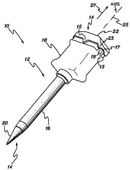
FIGURE 1 illustrates a perspective view of a trocar 10 embodying one
aspect of the present invention. This aspect of the invention includes a
cannula
assembly 12 and an obturator 14. Cannula assembly 12 includes a cannula tube
section 16 and a cannula head assembly 18. Obturator 14 includes pointed tip
20, a
CA 02458675 2004-02-25
WO 03/020140 PCT/US02/25818
cap assembly 22, and a shaft 24 (shown in FIGURE 3) between pointed tip 20 and
cap assembly 22. Cannula tube 16 comprises an essentially hollow tube in which
obturator 14 is inserted prior to surgery and from which obturator 14 is
withdrawn
after insertion into the body cavity. Cannula head assembly 18 is typically
adapted
to be held by the surgeon, for example, during insertion of trocar 10 or
withdrawal
of obturator 14. Cannula head assembly 18 may also provide means for
introducing one or more gases through the cannula, for example, for
insufflating a
body cavity when providing a pneumoperitoneum. Obturator cap assembly 22
typically provides a surface upon which the surgeon can push when inserting
the
trocar 10 through the tissue being penetrated and also provides a means for
grasping obturator 14 when removing obturator 14.
One aspect of the present invention illustrated in trocar 10 is the
interrelationship between the geometry of cannula head assembly 18 and cap
assembly 22 which aids in the removal obturator 14 from cannula assembly 22.
According to this aspect of the invention, head assembly 18 includes at least
one
bearing surface 19 and cap assembly 22 includes at least one bearing surface
23
that impinge upon each other when cap assembly 22 is rotated about its axis,
indicated by line 25 in FIGURE 1, whereby obturator 14, that is, the tip 20,
shaft
24, and cap assembly 22, is axially deflected, in the direction generally
indicated by
arrow 27. Bearing surfaces 19, 23 are typically located on bosses 13,
projections
15, or recesses 17 in the cap assembly 22 or head assembly 18. As shown in
FIGURE 1, these at least one bearing surfaces 19, 23 on bosses 13, projections
15,
or recesses 17 may be two or more bearing surfaces located along any side of
head
assembly 18 and the cap assembly 22, and may even be located on the top
surface
of head assembly 18 and the bottom surface of cap assembly 22. For example,
for
the rectangular cap assembly 22 shown in FIGURE 1, recesses 17 are located
along
either end of cap assembly 22, bosses 13 are also located along either end of
cannula head assembly 18 and projections 15 are located along the sides of cap
11
CA 02458675 2004-02-25
WO 03/020140 PCT/US02/25818
assembly 22. Cap assembly 22 shown in FIGURE 1 is rectangular in shape, but
cap assembly 22 may take any shape including circular, square, or ellipsoidal,
among others. Regardless of the shape of the cap assembly 22 and head assembly
18 and the number, location, and shape of bosses 13, projections 15, and
recesses
17, the same function is effected, that is, obturator 14 can be axially
deflected
relative to cannula 12 when rotated about its axis 25. Such a configuration
provides a relatively convenient means of removing obturator 14. Though in the
aspect shown in FIGURE 1, obturator 14 is shown deflecting in the direction
generally indicated by arrow 27, the present invention may also be implemented
in
such a way that obturator 14 is deflected in a direction opposite to arrow 27,
if
desired. For example, to aid in the insertion of obturator 14 through the skin
of the
patient.
The axial deflection of obturator 14 provides an effective means of
removing obturator 14 from the tissue into which it is inserted. The manual
rotation
of the obturator cap assembly 22 is illustrated in FIGURE 2 in which a hand 29
of a
surgeon is shown in the act of rotating cap assembly 22 in the direction
indicated
by arrows 21. Typically, cannula assembly 12 is restrained from moving while
cap assembly 22 is rotated, for example, restrained by the other hand of the
surgeon. This rotation, though preferably performed manually by the surgeon,
can
also be automated and performed remotely, for example, by a computer-
controlled
servo-mechanism.
Trocar 10 and the relative displacement of obturator 14 with respect to
cannula 16 and cannula head assembly 18 shown in FIGURE 1 are illustrated in
FIGURE 3. After cap assembly 22 is rotated, as shown in FIGURE 2, and
deflected according the present invention, obturator 14 can be removed from
cannula 16 as generally shown in FIGURE 3 by arrow 27. Also shown in FIGURE
3 is obturator shaft 24 which extends from obturator tip 20 to obturator cap
12
CA 02458675 2004-02-25
WO 03/020140 PCT/US02/25818
assembly 22.
The bearing surfaces on cap assembly 22 may take various forms, some of
which are illustrated in FIGURES 4A through 4D. FIGURE 4A illustrates a side
view of cap assembly 22 a partial view of head assembly 18 shown in FIGURE 1.
Only the top of head assembly 18 is shown in this figure. Cap assembly 22
includes
a central axis 25 which corresponds to the axis of, for example, obturator 14
(not
shown). According to this aspect of the invention, head assembly 18 and cap
assembly 22 include at least one set of cooperating surfaces that bear against
each
other, preferably at an angle, to promote sliding engagement and axial
deflection of
obturator 14 relative to cannula head 18 and cannula 12. In the aspect of the
invention shown in FIGURE 4A, head assembly 18 includes an annular recess 26
which is interrupted by at least one boss 28, preferably at least two bosses
28. Boss
28 may take many geometric forms and still effect the desired function, for
example, boss 28 may have a rectangular shape, as shown in FIGURE 4A, or semi-
circular, semi-ellipsoidal, trapezoidal, triangular, conical, parabolic,
hyperbolic, or
any other smooth curve or polygonal shape. Cap assembly 22 includes at least
one
recess 30, again, preferably, at least two recesses 30 which is shaped to
cooperate
with boss 28. Again, recess 30 may take many geometric forms, such as the
trapezoidal shape shown in FIGURE 4A, or any of the shapes or contours
described
above for boss 28.
According to this aspect of the invention, either boss 28 or recess 30
include at least one inclined surface or ramp. For example, in FIGURE 4A,
recess
30 includes two inclined surfaces 32 which can bear against the sides 33, for
example, the corners, of boss 28. The one or more surfaces 32 are typically
inclined at an angle of about 45 degrees to the axis 25, but may be inclined
at any
angle between about 10 degrees and about 80 degrees, and are preferably
between
about 30 degrees to about 60 degrees to the axis 25. Typically, cap assembly
22
13
CA 02458675 2004-02-25
WO 03/020140 PCT/US02/25818
and head assembly 18 include at least two mating surfaces 32, 33 located on
opposite sides of cap assembly 22 to provide a relatively balanced upward
thrust on
obturator cap 22 of obturator 14 relative to cannula 12. As noted, above the
thrust
effected by the mating surfaces may also provide a downward thrust.
In operation, when obturator 14 is inserted into cannula assembly 12, the
surface 30a of recess 30 contacts the surface 28a of boss 28, though a
clearance
may also be present between surface 30a and surface 28a. According to this
aspect
of the invention, when the surgeon rotates cap assembly 22 relative to cannula
12,
for example, as shown in FIGURE 2, at least one inclined surface 32 of recess
30
impinges and slidably engages boss 28 whereby the cap assembly 22 is axially
deflected as indicated by arrows 34. This upward thrust of obturator 14,
though
slight, can provide sufficient force and displacement to disengage the tip 20
of
obturator 14 from the tissue, for example, into which obturator 14 is
inserted.
Alternative bearing surface configurations that can be used on head
assembly 18 and cap assembly 22 are illustrated in FIGURES 4B through 4D.
FIGURE 4B illustrates an obturator cap 222 having at least one rectangular
recess
230 and a cannula head assembly 218 having at least one semicircular boss 228.
FIGURE 4C illustrates an obturator cap 322 having at least one semi-
ellipsoidal
boss 328 and a cannula head assembly 318 having at least one trapezoidal
recess
330. FIGURE 4D illustrates an obturator cap 422 having at least one semi-
circular
projection 430 and a cannula head assembly 418 having at least one rectangular
recess 428. As described with respect to FIGURE 4A, the respective bosses and
recesses of FIGURES 4B through 4D slidably engage and axially deflect
obturator
14 when obturator cap assembly 22, 222, 322, 422, is rotated about its
respective
axis while cannula assembly 12 is held generally stationary. Of course, many
other
combinations of bosses, projections, and recesses may be used to effect the
desired
sliding engagement and axial deflection.
14
CA 02458675 2004-02-25
WO 03/020140 PCT/US02/25818
Further aspects of the present invention are illustrated in FIGURES SA
through SC. FIGURE SA illustrates a cross-section of an obturator cap 622
having at least one semi-circular projection 630 and a cross-section of a
cannula
head assembly 618 having at least one semi-circular recess or slot 628.
Obturator
cap 622 is attached to obturator shaft 624. The sectional view SB-SB
identified in
FIGURE SA is shown in FIGURE SB. As shown in FIGURE SB, recess 628 is a
slot, for example, a circumferential slot, having rounded ends. The cross-
section
of slot 628 as indicated by sectional view SC-SC is shown in FIGURE SC. The
obturator cap 622 and projection 630 are shown in phantom in FIGURE SC. As
shown in FIGURE SC, slot 628 includes inclined ends that act as surfaces upon
which semi-circular projection 630 can bear when obturator cap 622 is rotated
relative to cannula head assembly 618. According to this aspect of the
invention,
the rotation of cap 622 causes the surface of projection 630 to bear against
and ride
up on either inclined surface of slot 628 and, in so doing, axially deflect
obturator
cap 622. The axial deflection of obturator cap 622 axially deflects obturator
shaft
624 as desired according to the present invention.
Though the bearing surfaces illustrated in FIGURES 1, 3, 4A through 4D,
and FIGURES SA through SC include bosses, projections, and recesses, among
other things, it will be apparent to those of skill in the art that other
forms of
geometric constructions can also be used to provide the desired deflection.
For
example, the bearing surfaces may comprise threaded surfaces, for example,
course
(UNC), fine (UNF), pipe (NPT), or acme-type threads. The bearing surfaces may
also be provided by gear teeth, splines, cams and cam followers, bearings
(ball,
roller, or needle), among other bearing surfaces. For example, further aspects
of
the present invention which provide axial deflection of the obturator relative
to the
cannula are shown and will be discussed below in reference to FIGURES 11A
through 11 D, FIGURES 12A through 12D, FIGURES 13 through 16, and
CA 02458675 2004-02-25
WO 03/020140 PCT/US02/25818
FIGURES 19A through 19E.
Though the aspects of the invention illustrated in FIGURES 4A through 4D and
FIGURE SA through SC provide effective means for axially deflecting obturators
and thereby facilitating removal of obturators from body cavities, as will be
discussed below, this aspect of the invention can be combined with the aspect
disclosed in FIGURES 10A and l OB to provide an even more advantageous device
and method.
Further aspects of the present invention are shown in FIGURES 6 through
9. FIGURES 6 and 7 illustrate an obturator 114 having a shaft 124, a tip 120,
and a
circular cap assembly 122. Obturator 114 may comprise one integral piece, for
example, an integral metal piece made of, for example, stainless steel,
titanium, or
aluminum. Obturator 114 may also be comprised of two or more individual
components of the same or dissimilar materials. For example, cap assembly 122,
shaft 124, and tip 120 may be formed from individual pieces and then
assembled,
for example, by means of mechanical fastening, for example, via threaded
connections. In addition, cap assembly 122 may be made of plastic having a
threaded connector, having internal or external threads, and shaft 124 may be
made
of stainless steel having a threaded end which engages the threaded connector
of
cap 122. Tip 120 may also be a individual steel part which is threaded either
internally or externally to shaft 124. Other modes of assembly will be
apparent to
those of skill in the art. Cap assembly 122 typically includes two
diametrically-
opposed triangular-shaped recesses 132 that can be used to effect the axial
deflection which characterizes one aspect of the present invention as
described
above.
FIGURES 8 and 9 illustrate a corresponding cannula assembly 112 having
cannula tube 116 and circular cannula head assembly 118 having triangular-
shaped
16
CA 02458675 2004-02-25
WO 03/020140 PCT/US02/25818
protrusions or bosses 128. Triangular-shaped bosses 128 may cooperate with
triangular-shaped recesses 132 of obturator cap 122 of FIGURE 6 to effect the
slidable engagement and axial deflection discussed above. As is typical in the
art,
cannula head assembly 118 may include one or more handles 120 and a gas supply
port 130. Handles 120 provide a means for grasping the trocar assembly during
insertion and removal. Of course, the general shape of cannula assembly 112
may
provide sufficient means for grasping the trocar and in one aspect of the
invention
no clearly defined handles may be provided. Gas supply port 130 communicates
with the inside of cannula tube 116 to provide a source of gas to the body
cavity,
for example, for insufflation. Port 130 may include a valve 131, for example,
a
hand-operated valve. Valve 131 may be used to introduce or remove fluids, that
is,
gases or liquids, from the body cavity. For example, valve 131 may include a
vent
position to vent gases from the body cavity to the ambient atmosphere. Head
assembly 118 in FIGURE 9, in addition to the triangular bosses 128, handles
120,
gas supply port 130 shown in FIGURE 8, illustrates an opening 119 in the top
of
head assembly 118 through which obturator 114 is typically inserted and
removed.
FIGURES 10A and l OB illustrate another aspect of the present invention
that can be present in trocar 10 of FIGURES 1 and 2 and in obturator 114 and
cannula assembly 116 of FIGURES 6 through 9. The items in FIGURE 10A are
numbered to correspond to the embodiment illustrated in FIGURE 1. FIGURE
10A illustrates a detailed view, partially in cross-section, of tip 20 of
obturator 14
and the distal end of cannula tube 16 of, for example, trocar 10 of FIGURE 1.
Obturator 14 includes a shaft 24 having a diameter 41. Tip 20 includes a
conically-
tapered end 42 that tapers from a diameter 44, typically a maximum diameter of
obturator 14, to a point 46, typically a rounded point though point 46 may be
a
sharp point. Tapered tip 20 is designed to permit relatively easy insertion of
trocar 10 through, for example, the muscle and facia of a patient and into a
body
cavity with minimal force and minimal damage to the tissue penetrated and
17
CA 02458675 2004-02-25
WO 03/020140 PCT/US02/25818
minimal damage to the internal tissues and organs. The surfaces of tapered end
section 42 typically make an angle of between about 5 degrees and about 30
degrees and is preferably between about 15 degrees and about 25 degrees with
the
axis of the obturator 14. Tip 20 also includes a second comically-tapered
surface 48
that tapers from diameter 44 of obturator 14 to diameter 41 of obturator shaft
24.
The surface of tapered section 48 typically makes an angle of between 10
degrees
and about 50 degrees and is preferably between about 20 degrees and about 25
degrees. Obturator 14 may also include a land section 50 having a first
leading
tapered surface 52 and a second trailing tapered surface 54 and a diameter 56.
Land section 50 helps to center obturator 14 within cannula tube 16 during
insertion and removal of obturator 14. Tapered surfaces 52, 54 aid in
facilitating
the insertion and removal of obturator 14 through the seals) of the cannula
head.
Diameter 56 of land section SO is typically greater than the diameter 41 of
shaft 24
but less than maximum diameter 44. Land section 50 typically has a length 58
approximately equal to diameter 41 of shaft 24.
As shown in FIGURE 10A, obturator 14 is inserted into cannula tube 16.
According to the present invention, cannula tube 16 is circular in cross-
section and
has a relatively uniform inside diameter 60 and outside diameter 62 along
almost
the entire length of tube 16. Inside diameter 60 is typically greater than
diameter
44 of obturator 14 to ensure that obturator 14 can be inserted without
obstruction
into cannula tube 16. However, according to one aspect of the present
invention,
cannula tube 16 includes an end 64 that is uniformly continuous and thus has
no
interruptions, such as slots, holes, or other apertures. Such a uniform,
continuous
geometry minimizes the resistance to insertion through and removal from
tissue,
minimizes the potential for tissue to be torn or damaged during insertion and
removal, and also minimizes the potential for damage to sutures, other
instruments,
and the trocar itself during insertion or removal. Furthermore, according to
this
aspect of the present invention, internal diameter 60 and outside diameter 62
of
18
CA 02458675 2004-02-25
WO 03/020140 PCT/US02/25818
cannula tube 16 decrease at end 64. As more clearly shown in the detailed view
of
FIGURE l OB, at end 64 of tube 16, the inside diameter 60 and outside diameter
62
taper to a minimum diameter, for example, inside diameter 60 may decrease to a
minimum diameter 66 and outside diameter 62 may decrease to minimum diameter
67. (In the detail shown in FIGURE l OB, for clarity of illustration,
diameters 44,
60, 62, 66, and 67 are shown as single-headed arrows. These single-headed
arrows
represent the respective double-headed arrows by which diameters are typically
illustrated, for example, the double-headed arrow representing diameter 44 in
FIGURE 10A.) In one embodiment, diameters 66 and 67 may essentially be the
same such that the cross-section of end 64 comes to a point. According to this
aspect of the present invention, inside diameter 66 of end 64 of cannula tube
16 is
smaller than diameter 44 of obturator 14.
According to this aspect of the invention, though the entire cannula tube 16
can be made of flexible material, at least end 64 of cannula tube 16 is
typically
made of a flexible material, for example, a thermoplastic polymer, such as a
polycarbonate or its equivalents, or a thermoset polymer, such as a
polyurethane or
its equivalents. Therefore, when obturator 14 having a maximum diameter 44,
greater than diameter 66, is inserted into the cannula tube 16 by means of,
for
example, the hole 119 (see FIGURE 9), and as tip 20 of obturator 14 approaches
end 64 of cannula tube 16, the surface 42 of tip 20 comes into contact with
the
inside diameter 66 of end 64. As tip 20 passes through end 64, surface 42
continues to pass through or bear against inside diameter 64 until the
diameter of
surface 42 approaches or exceeds diameter 66. Since end 64 is comprised of a
flexible material, as diameter 44 of tip 20 approaches and bears against
inside
diameter 66, inside diameter 66 will radially deflect until the inside
diameter
reaches or exceeds diameter 44. After diameter 44 passes diameter 66, the
flexible
end 64 recovers, that is, elastically, though some incidental plastic
deformation
may occur, to essentially its original undeflected diameter, for example, a
diameter
19
CA 02458675 2004-02-25
WO 03/020140 PCT/US02/25818
less than diameter 44. In this aspect of the invention, after the diameter 44
passes
inside diameter 66, inside diameter 66 of end 64 bears against the surface 48,
as
shown in FIGURE IOB. In a preferred aspect, inside diameter 66 of flexible end
64
returns to a diameter wherein outside diameter 67 is less than diameter 44.
The
resulting assembled trocar 10 having cannula 16 and obturator 14 provides a
relatively uniform transition between surface 42 of tip 20 and the outside
surface of
end 64 such that little or no resistance is provided and little or no damage
occurs
when subsequently inserting trocar 10 through tissue.
As is typical in the art, trocar 10 may be inserted through a patient's skin
by
first cutting a small incision in the skin. When tip 20 of obturator 14 has a
pointed
tip or a tip with cutting blades, skin incision may not be necessary. When
trocar 10
penetrates the skin and underlying tissue and accesses the body cavity to be
examined or treated, for example, the chest cavity, obturator 14 is removed
from
cannula 16. According to the present invention, the obturator 14 may be
removed
from trocar 10 by exerting an axial force on the carmula cap assembly, for
example,
cap assembly 22 (see FIGURE 1) while manually restraining the cannula
assembly,
for example, by holding cannula assembly 12 by means of head assembly 18 of
FIGURE 1.
With reference to FIGURES 10A and l OB, as obturator 14 is withdrawn,
tapered surface 48 of obturator 14 bears against the surface of inside
diameter 66 of
tip 64 and, again, diameter 66 is radially deflected. Again, diameter 66 of
flexible
end 64 continues to radially deflect (again, preferably elastically though
some
plastic deformation may occur) as obturator 14 is withdrawn until diameter 66
meets or exceeds diameter 44 of tip 20, after which the obturator can be
removed
typically without obstruction and the diameter 66 can flexibly return to a
diameter
that approaches or attains its original diameter. It will be understood by
those of
skill in the art that the diameter 66 may not return to its original diameter
due to
CA 02458675 2004-02-25
WO 03/020140 PCT/US02/25818
plastic deformation during insertion or removal of obturator 14. However, in
one
aspect of the invention, flexible cannula tube 16 may be removable and
disposable
such that re-use is not required. Similarly, according to one aspect of the
invention, the cannula head assembly, for example, head assembly 118 may also
be
disposable or reusable.
However, according to one aspect of the invention, the axial force applied
to the obturator 14 is provided by the rotation of the obturator 14 about its
axis and
the slidable engagement of one or more bearing surfaces on obturator cap
assembly 22 and cannula head assembly 18 (see FIGURE 1 ). That is, though the
inventions disclosed in FIGURES 1,2, 3, 4A through 4D, SA though SC, 6 through
9, and FIGURES 11A through 11D, and FIGURES 12A through 12D and the
invention disclosed in FIGURES 10A and lOB may be practiced independently,
these inventions may also be combined to provide a trocar assembly that
provides
the benefits of both inventions, that is, unobstructed ease of insertion into
a body
cavity and ease of removal of the obturator from tissue and from the cannula
with
minimal damage to tissue.
FIGURES 11 A through 11 D illustrate a further aspect of the present
invention. FIGURE 11A illustrates an obturator cap 722 attached to an
obturator
shaft 714 and a cannula head assembly 718 having a rotatable lever 750. Lever
750 is rotatably mounted to head assembly 718 by means of pin 751. The section
view identified by reference numbers 11B-11B in FIGURE 11A is shown in
FIGURE 11B. As shown in FIGURE 11B, lever 750 includes a notch 752. A
perspective view of lever 750 is shown in FIGURE 11D which clearly shows notch
752 and pin 751. FIGURE 11 C illustrates the axial deflection of cap 722 and
shaft 714 according to this aspect of the invention. As shown by arrow 760 in
FIGURE 11 C, the desired axial deflection of shaft 714 is effected by
pivotally
rotating lever 750 about pin 751 whereby the surface of notch 752 bears
against the
21
CA 02458675 2004-02-25
WO 03/020140 PCT/US02/25818
bottom of cap 722 and axially deflects cap 722 and shaft 714. Though a single
lever 750 is shown in these figures, one or more levers may be used. The shape
of
lever 750 and its means of attachment to head assembly 718 are not limited to
those
shown. The shape of lever 750 and its means of attachment may be modified as
desired to effect the desired function. In addition, according to the present
invention, lever 750 may be mounted to obturator cap 722, instead of to head
assembly 718, and still effect the desired deflection.
FIGURES 12A through 12D illustrate a further aspect of the present
invention. FIGURE 12A illustrates an obturator cap 822 attached to an
obturator
shaft 814 and a cannula head assembly 818 having at least one moveable wedge
850. Obturator cap 822 includes at least one wedge-shaped recess 855,
corresponding to wedge 850, having a complementary bearing surface 856 (shown
most clearly in FIGURE 12C). Wedge 850 is slidably mounted in a slot 853 (see
FIGURE 12C) in head assembly 818 by means of tab 851. Wedge 850 includes a
bearing surface 852. The section view identified by reference numbers 12B-12B
in FIGURE 12A is shown in FIGURE 12B. A perspective view of wedge 850 is
shown in FIGURE 12D which clearly shows bearing surface 852 and tab 851. As
shown in FIGURE 12B, wedge 850 is slidable, as indicated by arrow 860, in slot
853 from a first position to a second position, shown in phantom by reference
number 850. According to the present invention, the axial deflection of cap
822 is
effected by sliding wedge 822 in the direction of arrow 860. FIGURE 12C
illustrates the axial deflection of cap 822 and shaft 814 according to this
aspect of the invention. The desired axial deflection of shaft 814 is effected
by
sliding wedge 850 along slot 853 as shown by arrow 860 whereby the bearing
surface 852 of wedge 850 bears against the corresponding surface856 in recess
855
of cap 822 and axially deflects cap 822 and shaft 814. The shape of wedge 850
and its means of attachment to head assembly 818 are not limited to those
shown.
The shape of wedge 850 and its means of attachment may be modified as desired
to
22
CA 02458675 2004-02-25
WO 03/020140 PCT/US02/25818
effect the desired function. For example, the angle of inclination of surface
852 of
wedge 850 may vary from about 5 to about 85 degrees, but is preferably between
about 20 and about 50 degrees. In addition, according to the present
invention,
wedge 850 may be slidably mounted to obturator cap 822, instead of to head
assembly 818, and the angled recess 855 may be located in head assembly 818,
instead of in cap 822, and still effect the desired deflection.
A broad range of sizes of cannulas 12 ( or 812, etc.) and obturators 14, (or
814, etc.) may be used for the present invention. However, cannula tube 16 is
typically sized to accommodate standard surgical instruments that could be
inserted
into tube 16 to treat a patient. For example, conventional surgical
instruments that
may be used with the present invention typically have outside diameters
ranging
from about 3 mm to about 1 S mm. Therefore, inside diameter 60 of cannula tube
16 may typically range from about 3 mm (0.118 inches) to about 15 mm (0.591
inches), and is preferably between about 5 mm (0.197 inches) and about 12 mm
(0.472 inches). In order to operate according to the present invention, the
maximum diameter 44 of obturator 14 is typically at least about 0.001 inches
(0.025 mm) to about 0.020 inches (0.51 mm) greater than the inside diameter 66
of
cannula 16, and is preferably between about 0.004 inches (0.102 mm) to about
0.007 inches (0.178 mm) greater than diameter 66. That is, the maximum
diameter 44 of obturator 14 typically ranges from about 0.119 inches (3 mm) to
about 0.611 inches ( 15.5 mm).
The inside diameter 60 of cannula 16 is typically slightly larger than the
maximum diameter 44 of obturator 14 to allow obturator 14 to slide in and out
of
cannula tube 16 with little or no obstruction or resistance. Diameter 60 is
typically
between about 0.005 inches ( 0.127 mm) to about 0.050 inches ( 1.27 mm) larger
than diameter 44, and is preferably between about 0.010 inches (0.254 mm) to
about 0.020 inches ( 0.508 mm) greater than diameter 44. It will be apparent
to
23
CA 02458675 2004-02-25
WO 03/020140 PCT/US02/25818
those of skill in the art that diameter 60 may even be larger than diameter
44, for
example, diameter 60 may be more than 0.050 inches larger than diameter 44.
But
the larger the clearance is between inside diameter 60 and outside diameter
44, the
larger the outside diameter 62 of cannula tube 16 must be. However, the larger
the
diameter 62 is, the larger is the wound or penetration through the tissue of
the
patient. Of course, the size of this penetration through the tissue is
preferably
minimized and, correspondingly, the clearance between diameter 44 and diameter
62 is preferably minimized. Thus, the diameter 60 is typically between about
0.124 inches ( 3.15 mm) to about 0.661 inches ( 16.79 mm).
Again, the outside diameter 62 of cannula tube 16 is preferably minimized
to minimize the size of the penetration through the tissue of the patient.
However,
the size of diameter 62 is dictated by, among other things, the inside
diameter 60
and the thickness of the tube 16 required to manufacture tube 16 (typically
made of
plastic), for example, to supply the desired rigidity. Accordingly, the
outside
diameter 62 of tube 16 typically ranges from about 0.165 inches (4 mm) to
about
0.761 inches (19.3 mm) and is preferably between about 0.365 inches ( 9.3 mm)
and about 0.577 inches (14.6 mm).
FIGURES 13 through 16 illustrate further aspects of the present invention.
The trocar 900 illustrated in these figures is marketed under the name
TroGard~
FinesseTM by the ConMed Corporation of Utica, New York. FIGURE 13
illustrates a perspective view of trocar 900 having a cannula assembly 912
including a cannula head assembly 918 and a cannula tube 916 and an obturator
914 having a pointed tip 920, a cap assembly 922, and a shaft 924 (shown in
FIGURE 15) between pointed tip 920 and cap assembly 922. The cannula tube 916
includes an opened end 964. Cannula head assembly 918 may include one or more
gas supply or removal ports 930 having a valve 931, which operate and function
in
the essentially the same fashion as port 130 and valve 131 shown in FIGURES 9
24
CA 02458675 2004-02-25
WO 03/020140 PCT/US02/25818
and 10. The use and operation of trocar 900 is essentially the same as trocar
10
shown in FIGURES 1, 2 and 3.
According to this aspect of the present invention, cannula head assembly
918 includes at least one recess 917, typically at least two evenly-spaced
recesses
917, and obturator cap assembly 922 include at least one projection 913,
typically
at least two evenly-spaced projections 913. Recesses 917 and projections 913
cooperate to effect the desired deflection of obturator 914 relative to
cannula
assembly 912. For example, in a fashion essentially identical to that
discussed
with respect to earlier aspects of the invention, after insertion of trocar
900 into a
body cavity, obturator 914 is at least partially removed from the body cavity
by
rotating the obturator 914 relative to cannula assembly 912. This is more
clearly
shown in FIGURE 14.
FIGURE 14 is a perspective view of trocar 900 that is similar to FIGURE
13 but illustrating the typical position of obturator 914 relative to cannula
assembly
912 after rotation and deflection of obturator 914. The rotation of obturator
914 is
generally illustrated by the curved arrow 921 and the resulting axial
deflection of
obturator 914 relative to cannula assembly 912 is generally illustrated by
arrow
927. Again, as before, the rotation of obturator 914 causes the surface of
recesses
917 to bear against and "ride-up" on projections 913 whereby obturator 914 is
axially deflected relative to cannula assembly 912. In the aspect of the
invention
shown in FIGURES 13 and 14, projections 913 and recesses 917 are generally
elliptical in shape, though, as discussed above, other shapes or contours may
be
used.
As shown in FIGURE 14, the deflection of cap assembly 922 also deflects
obturator tip 920 to effect at least partial removal of obturator 914 from the
body
cavity. Open end 964 of cannula tube 916 and obturator tip 920 may include the
CA 02458675 2004-02-25
WO 03/020140 PCT/US02/25818
geometry and geometrical relationship illustrated in FIGURES 10A and l OB,
that
is, the geometry of tip 920 may radially deflect open end 964 as obturator 914
is
axially deflected while providing a smooth and continuous outer surface.
However, though in one aspect of the invention, the outer surface of open end
964
is smooth and continuous, having no obstructions, dislocations, or slots,
according
to the aspect of the invention shown in FIGURES 13 and 14, open end 964 may
also include one or more axial slots 965, to more readily allow open end 964
to
radial deflect when impinged upon by the surfaces of tip 920. (This
impingement
and deflection are again clearly shown in FIGURES 10A andlOB.)
FIGURES 15 and 16 illustrate cross-sectional views of trocar 900 shown in
FIGURES 13 and 14, respectively. For illustrative purposes, port 930, valve
931,
and obturator shaft 924 are not shown in cross section in FIGURES 15 and 16.
As
shown in FIGURE 15, when obturator 914 is inserted into cannula assembly 912
prior to insertion into a body cavity by a surgeon, the outer surface of open
end 964
of cannula tube 916 and the outer surface of tip 920 of obturator 914 provide
a
relatively smooth profile which minimizes the insertion effort required by the
surgeon and minimizes the potential for damaging skin, tissues, and internal
organs
during insertion, that is, there are no projecting edges upon which tissue can
be
damaged. As shown in FIGURE 16, during and after obturator 914 is axially
deflected, the cooperating geometry of open end 964 and tip 920 radially
deflect
open end 964 so that tip 920 can readily pass the restriction provided by open
end
964 and allow for easy removal of obturator 914 by the surgeon.
FIGURES 15 and 16 also illustrate the seal element 970 located in cannula
head assembly 918. Sealing element 970 is typically made from a resilient or
elastomeric material, for example, silicone rubber, polyurethane elastomer,
neoprene or thermo plastic elastomer. Sealing element 970 allows for the easy
insertion and removal of obturator shaft 924 into cannula assembly 912 while
26
CA 02458675 2004-02-25
WO 03/020140 PCT/US02/25818
minimizing the release of fluids, that is, liquids or gases, from the cannula
assembly 912. Sealing element 970 is more completely illustrated and described
with respect to FIGURES 17, 18A, 18B, and 18C.
FIGURE 17 illustrates a perspective view of the end of cannula assembly
912 having head assembly 918 and tube 916. Sealing element 970 is positioned
in
cannula head 918. FIGURES 18A, l8B,and 18C illustrate a top view, cross-
sectional view, and bottom view, respectively, of sealing element 970. As
shown
in FIGURE 18A, sealing element 970 is circular in shape and includes a
centrally
located aperture or hole 972, though which the obturator shaft 924 is inserted
and
removed, and a top surface 974. Sectional view B-B identified in FIGURE 18A is
shown in FIGURE 18B. As shown iri FIGURE 18B, sealing element 970 includes
a bottom surface 976 and an internal cavity 978. Bottom surface 976 comprises
a
membrane 979 which includes at least one aperture 975, for example, one or
more
narrow slits, though other shaped apertures may be used. The length of
aperture
975 is designed to allow passage of obturator shaft 924 while minimizing
leakage
of fluids. The thickness of membrane 979 is typically designed to withstand
the
differential pressure across it which minimizes the passage of fluid through
aperture 975. If two or more narrow slits are used in membrane 979, the slits
are
preferably radially directed and equally spaced in membrane 979. The profile
of
the outside diameter of sealing element 970 is adapted to be inserted and
retained
within head assembly 918. As shown in FIGURES 15 and 16, sealing element
970 may be sized to be inserted and retained within head assembly 918 by
simple
interference fit. However, sealing element 970 may also be retained by
appropriate
fasteners or retaining elements, such as by means of a plastic or metallic
seal-
retaining ring. Bottom view C-C identified in FIGURE 18B is shown in FIGURE
18C. The relative length of aperture 974 is shown in FIGURE 18C.
27
CA 02458675 2004-02-25
WO 03/020140 PCT/US02/25818
When inserting obturator 914 into cannula assembly 912, tip 920 is inserted
into and through aperture 972 and then through aperture 974. The aperture 972
is
sized so that its diameter is slightly smaller than the smallest diameter of
obturator
shaft 924 or the smallest diameter surgical instrument to be used. For
example, the
diameter of aperture 972 is slightly smaller than diameter 41 in FIGURE 10A.
This
interference fit between the resilient diameter of aperture 972 and shaft 924
minimizes the passage of fluids from cavity 978 to the ambient environment
during
insertion and removal of obturator 914. As the tip 920 of obturator 914 passes
through aperture 974, the narrow width of aperture 974, typically simply a
slit in
membrane 979, provides a sealing means. This sealing means minimizes the
passage of fluids from within cannula head 918 to sealing element cavity 978,
and
also to the ambient environment. This prevention or minimization of fluid
passage
is essentially maintained while the obturator 914 is inserted, retained in,
and
removed from cannula assembly 912. When obturator 914 is removed from
cannula assembly 912 and shaft 924 is removed from apertures 972 and 975, the
mating surfaces of aperture 974 provide a sealing means which minimizes the
passage of fluids from cannula head 918 to the ambient environment.
It will be understood by those of skill in the art that the diameter and
thickness of sealing element 970, the size of apertures 972 and 974, and the
thickness of membrane 979 may vary and depending upon the size of cannula head
918, the size of obturator 914, and the difference in pressure across membrane
979
that needs to be sealed, among other things. However, in the aspect of the
invention shown in FIGURE S 18A-1BC, the outside diameter of sealing element
970 is between about 0.625 inches and about 0.75 inches; the thickness of
sealing
element 970 is between about 0.25 inches to about 0.50 inches; the diameter of
aperture 972 is about 0.0625 inches to about 0.1875 inches; the length of
aperture
974 is between 0.1875 inches to about 0.25 inches; and the thickness of
membrane
979 is between about 1 mm to about 3 mm.
28
CA 02458675 2004-02-25
WO 03/020140 PCT/US02/25818
A further aspect of the present invention is illustrated in FIGURES 19A
through 19E. FIGURES 19A through 19C are a side view, top view, and
perspective view, respectively, of a trocar 1000 according this aspect of the
invention. FIGURE 19A illustrates a side elevation view of trocar 1000 having
a
cannula assembly 1012 including a cannula head assembly 1018 and a cannula
tube
1016 and an obturator 1014 including a cap assembly 1022, and a shaft 1024
(See
FIGURE 19C.). Cannula head assembly 1018 may include one or more gas
supply or removal ports 1030 having a valve 1031, which operate and function
in
the essentially the same fashion as port 130 and valve 131 shown in FIGURES 9
and 10. The use and operation of trocar 1000 is essentially the same as trocar
10
shown in FIGURES 1, 2 and 3, except as described below. Though not shown in
FIGURE 19A, in one aspect of the invention, cannula head 1018 includes a
sealing
element similar to sealing element 970 shown in FIGURES 18A through 18C.
Cannula tube 1016 and obturator 1014 may include the similar geometry and
geometrical relationship illustrated in FIGURES 10A and IOB.
FIGURE 19B illustrates a top view of trocar 1000 shown in FIGURE 19A.
As shown, according to this aspect of the invention obturator cap 1022 is oval
or
egg-shaped. (Note that cannula head 1018 will also have a comparable shape. )
This shape not only provides a convenient shape that facilitates handling
and rotation of obturator cap 1022 by the surgeon, but the shape shown in
FIGURE 19B also provides a corresponding bearing surface contour that effects
the desired deflection when rotated. The shape of obturator cap 1022 (and
cannula
head 1018) may also have other shapes, for example, circular, rectangular,
square,
and triangular, among others, and still effect the desired invention, though
these
shapes may not be as easily to manipulated by the surgeon.
According to this aspect of the present invention, the deflection of obturator
1014 relative to cannula head assembly 1018 is effected by rotating obturator
cap
29
CA 02458675 2004-02-25
WO 03/020140 PCT/US02/25818
1022 relative to cannula head assembly 1018 as indicated by arrow 1021 whereby
the bottom surface 1017 of obturator cap 1022 bears against the top surface
1013 of
head assembly 1018. That is, unlike earlier aspects of the invention in which
a
recess or projection provided one or more bearing surfaces, in this aspect of
the
invention, the entire bottom surface 1017 of obturator cap 1022, and any
portion
thereof, and the entire top surface 1013 of head assembly 1018, and any
portion
thereof, may act as a bearing surface to cause the deflection of obturator
1014
relative to cannula 1012. It will be understood by those of skill in the art
that only
a portion of surface 1017 or surface 1013 may provide a bearing surface and
the
entire surfaces 1017 and 1013 may not be impinged upon. For example, while the
cannula assembly 1012 is held by the surgeon and the obturator 1014 is
twisted, as
the obturator 1014 rotates, the point of impingement of the upper surface 1017
upon the lower surface 1013 will typically vary with rotation as the upper
surface
1017 "rides up on" the lower surface 1013. This impingement and deflection are
more clearly illustrated in FIGURE 19D. Though the surfaces 1017 and 1013 in
FIGURE 19A are shown as being generally curvilinear in shape, these surfaces
may
also be linear or planar and still effect the desired deflection upon rotation
(for
example, as shown in FIGURE 19E).
FIGURE 19C illustrates a perspective view of trocar 1000 shown in
FIGURES 19A and 19B. This perspective view is taken from a position slightly
below the horizontal to better illustrate the shape of the features of this
aspect of
the invention. In FIGURE 19 shows obturator 1014 somewhat withdrawn from
cannula 1012 to facilitate illustration of the geometry of obturator cap 1022
and
cannular head assembly 1018. As shown, bearing surface 1017 of obturator cap
1022 is a curved surface. When obturator 1014 is inserted in cannula 1012,
bearing
surface 1017 abuts surface 1013 of cannula head assembly 1018. Though not
shown in FIGURE 19C, the surface 1013 of cannula head assembly 1018 has a
shape similar to surface 1017. Obturator shaft 1024 is also shown in FIGURE
CA 02458675 2004-02-25
WO 03/020140 PCT/US02/25818
19C. The rotation and deflection of obturator 1014 relative to cannula 1012 is
illustrated in FIGURE 19D.
FIGURE 19D illustrates a perspective view of trocar 1000 shown in
FIGURES 19A, 19B, and 19C. The unrotated obturator cap 1022 is shown in
phantom to illustrate the relative rotation and deflection of obturator 1014
relative
to cannula 1012. The relative rotation of obturator 1014 is indicated by
curved
arrow 1021. Due to the geometry of mating surface 1013 and 1017, as obturator
1014 is rotated, typically manually by a surgeon while the surgeon holds
cannula
1012 stationary, at least some portion of surface 1017 bears against and
"rides up"
on surface 1013 lifting or displacing obturator 1014 relative to cannula 1012.
A
rotation as small as 5 degrees will result in a relative deflection of
obturator 1014;
however, obturator 1014 will typically be rotated at least 1 S degrees,
preferably at
least 90 degrees, to effect the desired deflection. As noted previously, this
axial
deflection of obturator 1014 typically at least partially dislodges the tip of
the
obturator shaft (see tip 920 in FIGURES 1 S and 16, for example) from the body
cavity in which trocar 1000 is inserted. As noted with respect to FIGURES 19A
through 19C, the deflection effected by rotating obturator 1014 may also be
sufficient to deflect the end of shaft 1024 beyond the flexible restriction at
the end
of cannula tube 1016, for example, as shown in FIGURES 10A and l OB.
FIGURE19E illustrates a side elevation view similar to FIGURE 19A of
another trocar 1100 according to another aspect of the present invention. In
this
aspect, trocar 1100 includes a obturator cap 1122 having a bearing surface
1117
and a cannular head 1118 having a bearing surface 1113 which mates with
surface
1117. In contrast to the embodiment shown in FIGURES 19A through 19D,
surfaces 1113 and 1117 are linear, or non-curved, yet can still effect the
desired
axial deflection when obturator cap 1112 is rotated relative to cannula head
1118.
31
CA 02458675 2004-02-25
WO 03/020140 PCT/US02/25818
While the invention has been particularly shown and described with
reference to preferred embodiment, it will be understood by those skilled in
the art
that various changes in form and details may be made to the invention without
departing from the spirit and scope of the invention described in the
following
claims.
*****
32