Note: Descriptions are shown in the official language in which they were submitted.
CA 02458686 2004-02-25
WO 03/020473 PCT/US02/19096
EMBEDDED QUICK CHANGE CONNECTOR FOR GRINDING WHEEL
Field of the Invention
The present invention relates to an abrasive article comprising a molded
abrasive disk with an integrally molded fastener, and in particular, to an
integrally
molded fastener with a single internal thread and a front surface that does
not extend
above a major surface of the abrasive disk.
Background of the Invention
The grinding wheel used on portable grinders generally consists of an
abrasive disk having a centrally located bore for receiving an internally
threaded collar
nut. The collar nut is adapted to be mounted to the externally threaded
spindle of the
grinder. Typically, a support flange is positioned on the spindle between the
grinding
wheel and an annular shoulder formed on the spindle to provide backing support
for the
grinding wheel. The support flange is typically configured to engage the
backside of the
abrasive disk around its outer radial edge. The direction of rotation of the
spindle when
the grinder is energized is such that the collar nut will self-thread onto the
spindle until
a tight frictional engagement is provided between the support flange and the
grinding
wheel. The grinding wheel can then be further tightened onto, or subsequently
removed from, the spindle by applying a wrench to the collar nut.
The collar nut in such conventional assemblies is typically not
permanently affixed to the abrasive disk, but rather is intended to be reused
when a
worn disk is replaced. In addition to the possibility of losing or misplacing
the collar
nut, this type of assembly is further disadvantageous from the standpoint that
replacement abrasive disks must have properly sized bores, which are not
uniform for
all brands and models. Moreover, the application of driving torque from the
spindle to
the abrasive disk is solely through the frictional interfaces between the
abrasive disk
and the spindle directly or between the abrasive disk and the supporting
flange and the
supporting flange and the spindle. Consequently, under load the abrasive disk
subassembly may slip at either of these frictional interfaces. To combat
slippage,
-1-
CA 02458686 2009-01-28
60557-7082
abrasive disk subassemblies are frequently tightened onto the spindle to such
a degree
that subsequent removal becomes difficult.
To alleviate some of these problems, various "hubbed"-type abrasive disk
subassemblies have been proposed, such as that shown in U.S. Pat. No.
4,694,615
(MacKay, Jr.). Hubbed-type abrasive disk subassemblies include a backing
flange that
is permanently affixed to the backside of the abrasive disk by attachment to
the hub
portion of the collar nut using a fastener. The collar nut, backing flange,
and fastener
become an integral part of the subassembly. The entire subassembly is thus
intended to
be discarded when the abrasive disk is worn.. Hubbed-type grinding wheels are
generally intended to be used in combination with specially designed support
flanges
adapted for engaging driving surfaces on the backing flange affixed to the
disk. While
the hubbed-type grinding wheels are much less susceptible to slippage
problems, they
are substantially more expensive than conventional non-hubbed grinding wheels
and
consequently are not as widely used.
U.S. Patent No. 5,339,571 (Timmons et al.) discloses an internally
threaded collar nut witlt a shape that is substantially noncircular so as to
preclude
relative rotation between the abrasive disk and the collar nut. The collar nut
is a
relatively expensive machined component that in some embodiments is discarded
with
the worn abrasive disk. The collar nut also includes a head portion that
extends above
one of the major surfaces of the abrasive disk, potentially interfering witli
the use of that
major surface on a work piece. Due to the mass of abrasive disks, it is
believed in the
art that a machined collar nut, such as disclosed in the `571 patent, is
required.
Accordingly, there is a need for an improved grinding wheel
subassembly that provides a positive means of coupling the grinding wheel to
the
spindle of the grinder without the expense of the hubbed-type wheel
subassemblies.
-2-
CA 02458686 2009-01-28
60557-7082
Brief Summary of the Invention
According to the present invention, there is
provided an abrasive article for a grinder having a motor-
driven, externally-threaded spindle, comprising: a molded
abrasive disk comprising abrasive particles distributed in a
binder, the abrasive disk comprising a working surface, a
depressed center surface depressed from the working surface,
and a second major surface opposite the working surface; and
a fastener comprising a body portion with an aperture and
first and second ends, an outwardly extending flange with a
front surface at the first end, tines having a portion
projecting perpendicular to the outwardly extending flange,
and mounting apertures adjacent the tines that connect the
molded abrasive disk and the front surface, and an inwardly
extending flange comprising a single internal thread at the
second end, the fastener being molded into the abrasive disk
so that the tines are embedded in the abrasive disk, the
front surface of the outwardly extending flange is coplanar
with the depressed center surface of the abrasive disk and
the inwardly extending flange is embedded between the
depressed center surface and second major surface of the
abrasive disk.
The present invention is directed to an abrasive
article for a grinder having a motor-driven, externally
threaded spindle. The abrasive article includes a
- 2a -
CA 02458686 2009-01-28
60557-7082
molded abrasive disk with an integrally molded fastener. The molded abrasive
disk comprises
abrasive particles distributed in a binder. In some embodiments, the abrasive
disk has a first
major surface, a second major surface and an integrally molded fastener. The
fastener has a
body portion with an aperture and first and second ends, an outwardly
extending flange with a
front surface at the first end, and an inwardly extending flange comprising a
single intemal
thread at the second end. In some embodiments, the fastener is molded into the
abrasive disk so
that the front surface does not extend above the first major surface.
In one embodiment, the first major surface comprises a planar working
surface. In another embodiment, the first major surface comprises a depressed
center
section and an annular working section such that the front surface of the
fastener does
not exteiid above the depressed center section. The front surface of the
fastener is
generally co-planar with the first major surface of the abrasive disk.
The fastener preferably includes mounting apertures at least partially
filled with abrasive particles and binder. In one embodiment, the outwardly
extending
flange comprises a planar portion generally perpendicular to an axis of the
thread. The
fastener typically comprises a stamped member.
The fastener also preferably includes tines embedded in the molded
abrasive disk. The tines can be generally perpendicular to the front surface
and
embedded in the molded abrasive disk. The tines embedded in the molded
abrasive
disk can optionally include a first portion generally perpendicular to the
front surface
and a second distal portion at an angle less then ninety degrees with respect
to the front
surface.
The body portion of the fastener typically includes a generally cylindrical
shape. In one embodiment, the body portion comprises a height greater than a
thickness of the molded abrasive disk. In another embodiment, the inwardly
extending
flange on the fastener is located between the first and second major surfaces
of the
molded abrasive disk.
A backing plate is typically used that engages with the spindle and the
second major surface of the abrasive disk. The molded abrasive disk is
compressed
-3-
CA 02458686 2004-02-25
WO 03/020473 PCT/US02/19096
between the backing plate and the outwardly extending flange when the abrasive
article
is engaged with the treaded spindle. The molded abrasive disk can optionally
include
an integrally molded reinforcing member, such as a scrim.
The present invention is also directed to a method of forming an abrasive
article for a grinder having a motor-driven, externally threaded spindle. The
method
includes the steps of preparing a mixture of abrasive particles dispersed in a
polymeric
binder. The mixture is poured into a form. A fastener with a single internal
thread is
positioned in the mixture so that a front surface of the fastener does not
extend above a
first major surface of the mixture. The polymeric binder is cured. The
abrasive article
is removed from the form. The fastener molded into the abrasive article can be
threaded onto a spindle of a tool. In an. alternate embodiment, the fastener
is located
with its front surface resting on a bottom surface of the form. The mixture is
poured
into the form around the fastener and cured. In some embodiment, the second
end of
the fastener extends above the mixture in the form. The mixture preferably
does not
migrate or flow into the center aperture of the fastener.
Brief Description of the Several Views of the Drawing
Further features of the invention will become more apparent from the
following detailed description of specific embodiments thereof when read in
conjunction with the accompany drawings.
Figure 1 is a perspective view of an abrasive article in accordance with
the present invention mounted on a tool.
Figure 2 is a cross-sectional view of an abrasive article in accordance
with the present invention.
Figure 3 is a top view of the abrasive article of Figure 2.
Figure 4 is a cross-sectional view of an alternate abrasive article in
accordance with the present invention.
Figure 5 is a perspective view of a fastener for use in an abrasive article
of the present invention.
-4-
CA 02458686 2004-02-25
WO 03/020473 PCT/US02/19096
Detailed Description of the Invention
Figure 1 is a perspective view of an exemplary abrasive article 10 in
accordance with the present invention. Abrasive article 10 is shown mounted to
tool
(as shown, an angle grinder) 12. The abrasive article 10 is threaded onto
externally
threaded spindle 14 on the tool 12. The spindle 14 defines a longitudinal axis
15
extending through the center of abrasive article 10. Although abrasive article
10 is
shown mounted to angle grinder 12, it would be understood that any tool having
a
rotational shaft could be used in conjunction with abrasive article 10 (e.g.,
a drill).
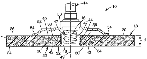
Figure 2 is a sectional view of the abrasive article 10 shown mounted to
externally threaded portion 16 of the spindle 14. The abrasive article 10
comprises a
molded abrasive disk 18 of abrasive material 20 molded around fastener 22. The
abrasive material 20 is typically abrasive particles distributed in a binder
molded to
form the desired shape. Prior to curing, the mixture of abrasive particles and
binder is
sufficiently plastic to assume the shape of the form into which it is placed.
In the
illustrated embodiment, the abrasive material 20 is formed to be a disk shape
or annulus
with a first major surface 24, a second major surface 26 and an edge surface
28. The
size of the edge surface 28 is determined by the thickness "d" of the molded
abrasive
disk 18. Although the edge surface 28 is illustrated as generally flat, the
abrasive
material 20 can easily be molded to have a variety of shapes. As used herein,
"molded
abrasive disk" refers to abrasive particles dispersed throughout and adhered
within a
polymeric binder formed into a self-supporting abrasive structure.
In the illustrated embodiment, the abrasive article 10 has a circular cross-
section. By "generally circular" it is meant that the abrasive article 10 is
round in
shape, and is typically circular, however other shaped (e.g., hexagonal) can
be used
without departing from the spirit and scope of the invention.
The fastener 22 includes an outwardly extending flange 30 with a front
surface 32. The fastener 22 is integrally molded in the molded abrasive disk
18 before
the abrasive material 20 is fully cured. Aperture 46 is formed by the fastener
22
-5-
CA 02458686 2004-02-25
WO 03/020473 PCT/US02/19096
displacing abrasive materia120 during the molding process. The fastener 22 is
preferably located in the molded abrasive disk 18 so that the outwardly
extending flange
30 is generally co-planar with, or slightly recessed below, the first major
surface 24.
The fastener is also preferably located in the physical and gravitational
center of the
molded abrasive disk 18.
In the embodiment of Figure 2, the fastener 22 is concentric with the
edge surface 28. The front surface 32 preferably does not extend above the
first major
surface 24. In some embodiments, the front surface 32 includes a generally
planar
portion 34 that is co-planar with the first major surface 24. For embodiments
where the
abrasive materia120 has sufficient thickness "d" the front surface 32 may be
recessed
below the first major surface 24.
Molding the fastener 22 into the abrasive material 20 allows a quick-
change fastener to be economically inserted into the abrasive article 10. The
fastener 22
is lightweight, concentric and rotationally fixed with respect to the molded
abrasive disk
18 so that the entire abrasive article 10 can be rotated to thread and
unthread the
fastener 22 from the threaded shaft 16, rather than by using wrenches, as was
previously
required. The result is a significant improvement in user convenience,
allowing quick
change of abrasive disks, which is desirable when each disk becomes worn or
when a
disk having different abrasive media is needed.
The outwardly extending flange 30 preferably includes one or more tines
36 that extend into the molded abrasive disk 18. The tines 36 can be
perpendicular to
the outwardly extending flange 30 or bent in various ways. For example, the
tines 36 in
Figure 2 include a first portion 38 that is perpendicular to the outwardly
extending
flange 30 and a second portion 40 that is parallel to the outwardly extending
flange 30.
This configuration enhances the structural integrity of the bond between the
fastener 22
and the molded abrasive disk 18. In particular, the tines 36 permit a
substantial level of
torque to be applied to the fastener 22 by the spindle 14 without slippage
between the
fastener 22 and the molded abrasive disk 18.
-6-
CA 02458686 2004-02-25
WO 03/020473 PCT/US02/19096
As illustrated in Figures 2 and 3, the tines 36 are formed from a portion
of the material comprising the outwardly extending flange 30. Consequently,
adjacent
to the tines 36 are mounting apertures 42 into which a portion of the abrasive
material
20 flows during molding of the abrasive article 10. The cured or hardened
abrasive
material 20 in the molding apertures 36 also prevent slippage between the
fastener 22
and the molded abrasive disk 18.
The fastener 22 includes a body portion 44 that extends rearward from
the outwardly extending flange 30. The body portion 44 forms aperture 46 in
the
abrasive materia120. The cross-section of the body portion 44 can be a circle,
oval,
polygon or any curvilinear shape. Non-circular cross sections for the body
portion 44
are desirable to maintain a positive lock between the fastener 22 and the
molded
abrasive disk 18.
In the embodiment of Figure 2, the body portion 44 extends above
second major surface 26 of the molded abrasive disk 18. The distal most end of
the
body portion 44 includes an inwardly extending flange 47 that forms a single
internal
thread 48 adapted to engage with the treaded portion 16 of spindle 14 (see
also, Figure
3). The internal thread 48 defines an axis 49 along which the threaded portion
16 is
received. The axis also preferably extends through the center of mass of the
abrasive
article 10.
Most grinding tools, such as the tool 12 illustrated in Figure 1, include a
backing plate that supports various types of the abrasive articles. In the
embodiment of
Figure 2, the spindle includes a collar 50 adapted to receive backing plate
52. In an
alternate embodiment, the backing plate 52 is threaded onto threaded portion
16. The
backing plate 52 is not attached to the abrasive article 10. In the
illustrated
embodiment, the backing plate 52 does not extend to the edges of the molded
abrasive
disk 18. The packing plate 52 is preferably removable when the abrasive
article 10 is
removed from the spindle 14. When the abrasive article 10 is discarded, the
backing
plate 52 is typically reused.
-7-
CA 02458686 2004-02-25
WO 03/020473 PCT/US02/19096
The backing plate 52 includes distal portions 54 that engage with second
major surface 26 of the abrasive article 10. When the abrasive article 10 is
attached to
the spindle 14, the abrasive material is compressed between the distal
portions 54 of the
backing plate 52 and rear surface 56 of the outwardly extending flange 30 on
the
fastener 22. This compressive relationship serves to further secure the
fastener 22 to
the molded abrasive disk 18.
Figure 4 illustrates an alternate abrasive article 100 in which the abrasive
material 102 is formed with a depressed center section 104. Consequently, the
first
major surface 106 includes a working surface 108, a tapered surface 110 and a
depressed center surface 112. Fastener 114 is integrally molded in the
abrasive material
102 so that flange 116 is generally co-planar with the depressed center
surface 112.
In the embodiment of Figure 4, fastener body portion 118 does not
extend above second major surface 120. Rather, the fastener 114 is fully
embedded in
the abrasive material 102. A portion of the abrasive material 102 forms a
sidewall 122
defining a portion of aperture 124 that receives threaded portion 16 of the
spindle 14.
Tine 126 extends generally perpendicular to the flange 116 while tine 128 is
bent
relative to the flange 116. In the embodiment of Figure 4, backing plate 130
extends
along the second major surface 120 substantially to the edge 132 of the
abrasive
material 102.
The method of the present invention includes the steps of preparing a
mixture of abrasive particles dispersed in a polymeric binder. The polymeric
binder is
typically thermoset, but can be thermoplastic. The mixture is poured into a
form. A
fastener with a single internal thread is positioned in the mixture so that a
front surface
of the fastener does not extend above a first major surface of the mixture.
The
polymeric binder is cured. The abrasive article is removed from the form. The
fastener
molded into the abrasive article can be threaded onto a spindle of a tool. In
an alternate
embodiment, the fastener is located with its front surface resting on a bottom
surface of
the form. The mixture is poured into the form around the fastener and cured.
In some
-8-
CA 02458686 2004-02-25
WO 03/020473 PCT/US02/19096
embodiment, the second end of the fastener extends above the mixture in the
form. The
mixture preferably does not migrate or flow into the center aperture of the
fastener.
Figure 5 is a perspective view of a fastener 150 having a single internal
thread 152 in accordance with the present invention. Fastener body portion 154
includes an outwardly extending flange 156 that is positioned near the first
major
surface of the abrasive material and an inwardly extending flange 158 that is
positioned
near the second major surface (see Figure 2). The inwardly extending flange
158
includes a notch 162, typically extending radially from aperture 164, that
provides edge
portions 166, 168 that are at different elevations with respect to the
outwardly extending
flange 156. The inwardly extending flange 158 forms a single internal thread
160. The
difference in elevations corresponds to the pitch of the threads 16 on the
spindle 14. As
used herein, "single internal thread" refers to a thread that extends less
than 360
around the inside perimeter of an aperture. The fastener 150 of Figure 5 can
preferably
be formed at extremely low cost using a stamping process.
Tines 170 are formed in the outwardly extending flange 156. The tines
170 extend from the outwardly extending flange 156 toward the inwardly
extending
flange 158. Since the tines 170 are intended to resist rotation of the
fastener 150
relative to the abrasive material, they are preferably shaped to resist torque
172. In the
illustrated embodiment, the tines 170 are stamped from the outwardly extending
flange
156 so that bend lines 174 for the tines 170 are generally in the direction of
the torque
172. Consequently, the torque 172 acts on the tines 170 perpendicular to the
bend lines
174.
Fasteners suitable for use in the present invention include a sheet metal
nut or the "Tinnerman" nut fastening device (also referred to as a "treadless
fastener")
described in U.S. Pat. No. 2,156,002 (Tinnerman). While the Tinnerman nut is
the
preferred fastening device, other types of fasteners may be used without
departing from
the spirit and scope of the invention. A commercially available fastener
suitable for the
present invention is a 1.5 inch (38.1 mm) quick-change button for mating with
a 5/8
inch diameter by 11 thread per inch shaft (15.875 mm diameter by 0.43 threads
per
-9-
CA 02458686 2004-02-25
WO 03/020473 PCT/US02/19096
mm), manufactured by Metal Products Engineering, Los Angeles, CA. Such
fasteners
can be formed for example from 28 gauge steel, although other materials (e.g.,
brass or
aluminum) may be used without departing from the spirit and scope of the
invention.
Abrasive material used in abrasive articles according to the present
invention is abrasive grains or particles disbursed in an organic binder. A
reinforcing
fibers or a reinforcing mesh or scrim may optionally be molded into or onto a
surface of
the abrasive article. Examples of filaments include polyester fibers,
polyamide fibers,
fiber glass, and polyaramid fibers.
Suitable organic binders for making the abrasive material include
thermosetting organic binder materials. Examples of suitable thermosetting
organic
polymers include phenolic resins, urea-formaldehyde resins, melamine-
formaldehyde
resins, urethane resins, acrylate resins, polyester resins, aminoplast resins
having
pendant a,R-unsaturated carbonyl groups, epoxy resins, acrylated urethane,
acrylated
epoxies, and combinations thereof. The binder and/or abrasive product may also
include additives such as fibers, lubricants, wetting agents, thixotropic
materials,
surfacants, pigments, dyes, antistatic agents (e.g., carbon black, vanadium
oxide,
graphite, etc.), coupling agents (e.g., silanes, titantates, zircoaluminates,
etc.),
plasticizers, suspending agents, and the like. The amounts of these optional
additives
are selected to provide the desired properties. The coupling agents can
improve
adhesion to the abrasive particles and/or filler. The binder chemistry may be
thermally
cured, radiation cured or combinations thereof. Additional details on binder
chemistry
may be found, for example, in U.S. Pat. Nos. 4,588,419 (Caul et al.),
4,751,137 (Tumey
et al.), 4,933,373 (Moren), and 5,436,063 (Follett et al.).
Typically, the abrasive particles have a moh's hardness of at least 5, 6, 7,
8, 9, or even 10. Suitable abrasive grains include fused aluminum oxide
(including
white fused alumina, heat-treated aluminum oxide and brown aluminum oxide),
silicon
carbide, boron carbide, titanium carbide, diamond, cubic boron nitride,
garnet, fused
alumina-zirconia, and sol-gel-derived abrasive particles, and the like. The
sol-gel-
derived abrasive particles may be seeded or non-seeded. Likewise, the sol-gel-
derived
-10-
CA 02458686 2004-02-25
WO 03/020473 PCT/US02/19096
abrasive particles may be randomly shaped or have a shape associated with
them, such
as a rod or a triangle. Examples of sol gel abrasive particles include those
described
U.S. Pat. Nos. 4,314,827 (Leitheiser et al.), 4,518,397 (Leitheiser et al.),
4,623,364
(Cottringer et al.), 4,744,802 (Schwabel), 4,770,671 (Monroe et al.),
4,881,951 (Wood
et al.), 5,011,508 (Wald et al.), 5,090,968 (Pellow), 5,139,978 (Wood),
5,201,916
(Berg et al.), 5,227,104 (Bauer), 5,366,523 (Rowenhorst et al.), 5,429,647
(Larmie),
5,498,269 (Larmie), and 5,551,963 (Larmie). The abrasive grains may also be
present
in the form abrasive agglomerates.
Abrading with abrasive articles according to the present invention may be
done dry or wet. For wet abrading, the liquid may be introduced supplied in
the form of
a light mist to complete flood. Examples of commonly used liquids include:
water,
water-soluble oil, organic lubricant, and emulsions. The liquid may serve to
reduce the
heat associated with abrading and/or act as a lubricant. The liquid may
contain minor
amounts of additives such as bactericide, antifoaming agents, and the like.
Abrasive
articles according to the present invention may be used with externally-
applied abrasive
compounds, such as those known as polishing or buffing compounds.
Abrasive articles according to the present invention may be used to
abrade workpieces such as aluminum and aluminum alloys, carbon steels, mild
steels,
tool steels, stainless steel, hardened steel, brass, titanium, glass,
ceramics, wood, wood-
like materials, plastics, paint, painted surfaces, organic coated surfaces and
the like.
A wide variety of backing plate shapes can be used depending upon the
end uses of the abrasive article. For example, the backing plate can be
tapered so that
the center portion of backing plate is thicker than the outer portions. The
backing plate
can have a uniform or non-uniform thickness. The backing plate can be
embossed.
The center of the backing plate can be depressed, or lower, than the outer
portions. The
edges of backing plate can be purposely bent to make a "cupped" disk if so
desired.
The edges of backing plate can also be smooth or scalloped.
The backing plate is sufficiently tough and heat resistant under severe
grinding conditions such that it does not significantly disintegrate or deform
from the
- 11 -
CA 02458686 2004-02-25
WO 03/020473 PCT/US02/19096
heat generated during use (e.g., during a grinding, sanding, or polishing
operation) and
will not significantly crack or shatter from the forces encountered during
manufacturing
of the abrasive article as well as during use. The backing plate preferably
exhibits
sufficient flexibility to withstand typical grinding conditions, and
preferably severe
grinding conditions. Embodiments of the present invention utilize a backing
plate that
exhibits appropriate shape control and are sufficiently insensitive to
environmental
conditions, such as humidity and temperature.
The backing plates can be made from various metals, such as steel,
aluminum, brass, etc or from a polymeric material. Polymeric backing plates
optionally
contains at least one of a thermoplastic binder material or a thermoset binder
material
and an effective amount of a filler and/or fibrous reinforcing material. By an
"effective
amount" of a reinforcing material, it is meant that the backing plate contains
a sufficient
amount of the reinforcing material to impart at least improvement in heat
resistance,
toughness, flexibility, stiffness, shape control, etc., discussed above.
A thermoplastic binder material is a polymeric material (e.g., an organic
polymeric material) that softens and melts when exposed to elevated
temperatures and
generally returns to its original condition (i.e., its original physical
state) when cooled to
ambient temperatures. During the manufacturing process, the thermoplastic
binder
material is heated above its softening temperature, or in some instances above
its
melting temperature, to cause it to flow and form the desired shape of the
abrasive
article. After the backing plate is formed, the thermoplastic binder is cooled
and
solidified. In this way the thermoplastic binder material can be molded into
various
shapes and sizes.
The backing plate can be formed, for example, by shaping or molding the
thermoplastic material and/or thermoset binder material using conventional
molding
techniques such as injection molding. Use of such molding techniques can
reduce the
amount of materials wasted in construction, relative to conventional "web"
processes.
Injection molding can also allow for the backing plate to be more concentric
than what
was previously available. Making the backing plate concentric aids in
minimizing or
-12-
CA 02458686 2004-02-25
WO 03/020473 PCT/US02/19096
eliminating wobbling during use of the abrasive disk. Additionally, for
example, a
concentric backing plate may allow tighter manufacturing tolerances to be kept
(i.e.,
when mounting the abrasive material and the fastener). Additionally, for
example,
higher concentricity of the abrasive disk can minimize curling of the edges of
the
backing plate. Molding technologies can also allow for controlling shrinkage
of the
backing plate during manufacturing, and allow for molding structural members
(e.g.,
ridges) into the backing plate, (as is known in the art), to help minimize or
prevent
warpage.
Web manufacturing processes can also be used to form the backing plate.
In a typical web manufacturing process, the backing plate for the abrasive
disk is made
in a continuous web form and then cut into the desired disk shape. Although
injection
molding techniques can be used to produce backing plates for the backing
plates
utilized in the present invention (to provide tighter manufacturing tolerances
as well as
avoid waste) this is not intended to mean that conventional "web" processes
cannot be
used. On the contrary, using conventional web processes to form the backing
plate may
be necessary when using certain embodiments of the backing plate (e.g.,
thermoplastic
and/or thermoset impregnated cloths).
Although the present invention has been described with reference to
preferred embodiments, workers skilled in the art will recognize that changes
may be
made in form and detail without departing from the spirit and scope of the
invention. In
addition, the invention is not to be taken as limited to all of the details
thereof as
modifications and variations thereof may be made without departing from the
spirit or
scope of the invention.
-13-