Language selection

Search

Patent 2458948 Summary

Third-party information liability

Some of the information on this Web page has been provided by external sources. The Government of Canada is not responsible for the accuracy, reliability or currency of the information supplied by external sources. Users wishing to rely upon this information should consult directly with the source of the information. Content provided by external sources is not subject to official languages, privacy and accessibility requirements.

Claims and Abstract availability

Any discrepancies in the text and image of the Claims and Abstract are due to differing posting times. Text of the Claims and Abstract are posted:

  • At the time the application is open to public inspection;
  • At the time of issue of the patent (grant).
(12) Patent: (11) CA 2458948
(54) English Title: A YIELDING ROCK BOLT
(54) French Title: BOULON D'ANCRAGE COULISSANT
Status: Deemed expired
Bibliographic Data
(51) International Patent Classification (IPC):
  • E21D 21/00 (2006.01)
  • E21D 21/02 (2006.01)
(72) Inventors :
  • MALTBY, DAVID (Australia)
(73) Owners :
  • GARFORD PTY LTD. (Australia)
(71) Applicants :
  • GARFORD PTY LTD. (Australia)
(74) Agent: FETHERSTONHAUGH & CO.
(74) Associate agent:
(45) Issued: 2011-07-12
(86) PCT Filing Date: 2002-09-06
(87) Open to Public Inspection: 2003-03-13
Examination requested: 2007-09-04
Availability of licence: N/A
(25) Language of filing: English

Patent Cooperation Treaty (PCT): Yes
(86) PCT Filing Number: PCT/AU2002/001223
(87) International Publication Number: WO2003/021081
(85) National Entry: 2004-02-27

(30) Application Priority Data:
Application No. Country/Territory Date
PR 7519 Australia 2001-09-06
2002950586 Australia 2002-08-06

Abstracts

English Abstract


A yielding rock bolt (10) arranged to be inserted into a hole in a rock
surface. The rock bolt comprises a shaft (12) having a widened portion (26)
adjacent a first end (20) thereof, arranged, in use, adjacent an inner end of
the hole. The rock bolt (10) also includes an anchor member (14) arranged to
be secured within the hole in the rock surface. A longitudinal bore is
provided in the anchor member (14) to receive a second end of the shaft (12),
the longitudinal bore being of a diameter slightly less than that of the
widened portion (20) of the shaft (12). A rock face engaging means (28) is
provided adjacent a second end of the shaft (12) to secure the second end of
the shaft (12) adjacent the rock face. Movement of the rock face causes the
widened portion (26) of the shaft (12) to be pulled through the longitudinal
bore in the anchor member (14).


French Abstract

L'invention concerne un boulon d'ancrage coulissant (10) destiné à être inséré dans un trou formé dans une surface rocheuse. Ce boulon d'ancrage comprend une tige (12) présentant une partie élargie (26), adjacente à une première extrémité (20) de ladite tige et placée, en cours d'utilisation, de façon adjacente à une extrémité intérieure du trou. Ce boulon d'ancrage (10) comprend également un élément d'ancrage (14) destiné à être fixé solidement à l'intérieur du trou formé dans la surface rocheuse. Un alésage longitudinal, formé à l'intérieur dudit élément d'ancrage (14), sert à recevoir une seconde extrémité de la tige (12), cet alésage longitudinal présentant un diamètre légèrement inférieur à celui de la partie élargie (20) de la tige (12). Un moyen (28), s'engageant vers la surface rocheuse et adjacent à une seconde extrémité de la tige (12), sert à fixer solidement la seconde extrémité de la tige (12) adjacente à la surface rocheuse. La partie élargie (26) de la tige (12) est tirée à travers l'alésage longitudinal, formé dans l'élément d'ancrage (14, par le mouvement de la surface rocheuse.

Claims

Note: Claims are shown in the official language in which they were submitted.


6

CLAIMS


1. A yielding rock bolt arranged to be inserted into a hole in a rock surface
which
comprises a shaft having a widened portion adjacent a first end thereof, the
first end being
arranged, in use, adjacent an inner end of the hole;

an anchor member arranged to be secured within the hole in the rock surface;

a longitudinal bore provided in the anchor member, the longitudinal bore being

arranged to receive a second end of the shaft and being of a diameter less
than that of the
widened portion of the shaft;

a rock face engaging means adjacent the second end of the shaft to secure the
second end of the shaft adjacent the rock face; and

the shaft comprising a plurality of peripheral cable strands spirally wrapped
around a
centre wire, the centre wire including a first segment adjacent the first end
of the shaft and a
second segment extending from the first segment toward the second end of the
shaft,
wherein the first segment has a diameter greater than the second segment such
that the first
segment has a diameter greater than the second segment such that the first
segment causes
the peripheral cable strands to be forced outwardly, thus creating the widened
portion of the
shaft;

wherein movement of the rock face causes the widened portion of the shaft to
be
pulled through the longitudinal bore in the anchor member.

2. A yielding rock bolt in accordance with claim 1, wherein the diameter of
the second
centre wire segment is generally equal to the diameter of the peripheral cable
strands.

3. A yielding rock bolt in accordance with either claim 1 or 2, wherein the
first
segment of the centre wire is constructed of a material softer than the
peripheral cable


7
strands such that the first segment of the centre wire is deformed as the
widened portion of
the shaft is pulled through the longitudinal bore of the anchor member.

4. A yielding rock bolt in accordance with any one of claims 1 to 3, wherein
the centre
wire includes a third segment adjacent the second end of the shaft, the third
segment of the
centre wire having a diameter greater than that of the first segment such that
the longitudinal
bore of the anchor member is not able to slide over the portion of the shaft
around the third
segment of the centre wire.

5. A yielding rock bolt in accordance with any one of claims 1 to 4, wherein
inner
surfaces of the longitudinal bore are constructed of a material softer than
the shaft such that
the inner surfaces of the longitudinal bore are deformed as the widened
portion of the shaft
is pulled through the longitudinal bore of the anchor member.

6. A yielding rock bolt in accordance with any one of claims 1 to 5, wherein
inner
surfaces of the longitudinal bore are subject to a metallurgical treatment to
prevent
molecular welding to the shaft.

7. A yielding rock bolt in accordance with claim 6, wherein the metallurgical
treatment
includes nitrocarburising.

8. A yielding rock bolt in accordance with any one of claims 1 to 7, wherein
the
longitudinal bore of the anchor member includes an outwardly tapered portion
adjacent a
first end of the anchor member, the first end of the anchor member being
adjacent, in use,
the widened portion of the shaft.


8
9. A yielding rock bolt in accordance with any one of claims 1 to 8, wherein
the shaft
is provided with a de-bonding sheath to allow the shaft to slide within the
hole in the rock.
10. A yielding rock bolt in accordance with any one of claims 1 to 9, wherein
the rock
face engaging means comprises a conical shaped plate member.

11. A yielding rock bolt in accordance with any one of claims 1 to 10, wherein
the
peripheral cable strands are secured together adjacent the first end of the
shaft by a clamp
member and the peripheral cable strands are splayed outwardly at the first end
of the shaft
to engage with side walls of the hole in the rock.

Description

Note: Descriptions are shown in the official language in which they were submitted.


CA 02458948 2009-07-30
TITLE

"A YIELDING ROCK BOLT"

BRIEF DESCRIPTION OF THE INVENTION
The present invention relates to a yielding rock bolt.

FIELD OF THE INVENTION

Seismic disturbances in underground mines are common. The forces involved in
such
disturbances can cause the tunnels of these underground mines to collapse and
the use of
rock bolts to prevent catastrophic collapse of the tunnel walls is known. The
rock bolts are
secured into holes drilled in tunnel walls and are designed to yield to a
certain extent to

prevent collapse of the tunnel walls. The movement which occurs as the rock
bolt yields
then provides warning to persons in the mine of possible collapse of the
tunnel.
SUMMARY OF THE INVENTION

In accordance with one aspect of the present invention there is provided a
yielding rock bolt
arranged to be inserted into a hole in a rock surface which comprises a shaft
having a
widened portion adjacent a first end thereof, the first end being arranged, in
use, adjacent an
inner end of the hole;

an anchor member arranged to be secured within the hole in the rock surface;

a longitudinal bore provided in the anchor member, the longitudinal bore being
arranged to
receive a second end of the shaft and being of a diameter less than that of
the widened
portion of the shaft;

a rock face engaging means adjacent the second end of the shaft to secure the
second end of
the shaft adjacent the rock face; and

the shaft comprising a plurality of peripheral cable strands spirally wrapped
around a centre
wire, the centre wire including a first segment adjacent the first end of the
shaft and a
second segment extending from the first segment toward the second end of the
shaft,

wherein the first segment has a diameter greater than the second segment such
that the first


CA 02458948 2009-07-30
2

segment has a diameter greater than the second segment such that the first
segment causes
the peripheral cable strands to be forced outwardly, thus creating the widened
portion of the
shaft;

30 wherein movement of the rock face causes the widened portion of the shaft
to be pulled
through the longitudinal bore in the anchor member.

DESCRIPTION OF THE DRAWINGS

The present invention will now be described, by way of example, with reference
to the
accompanying drawings, in which:

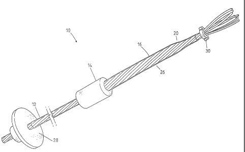
35 Figure 1 is a perspective view of a yielding rock bolt in accordance with
the present
invention; and

Figure 2 is a cross sectional view of the rock bolt of Figure 1.
DESCRIPTION OF THE INVENTION

Referring to the Figures, there is shown a yielding rock bolt 10 comprising a
shaft 12 and an
40 anchor member 14. The shaft 12 comprises a plurality of peripheral cable
strands 16
spirally wrapped around a centre wire 18 (commonly referred to as a `king
wire').

The centre wire 18 may comprise more than one sections and includes a segment
having an
increased diameter adjacent a first end 20 thereof. The centre wire 18 of the
rock bolt 10
shown in the Figures comprises a first centre wire 22 adjacent the first end
20 and a second

45 centre wire 24 extending from the first centre wire 22 to a second end of
the shaft 12. The
second centre wire 24 is of a diameter generally equal to that of the
peripheral cable strands
16. The first centre wire 22 has a diameter greater than that of the second
centre wire 24
such that the shaft has a widened portion 26 adjacent the first end 20
thereof.

The anchor member 14 includes a longitudinal bore such that the shaft 12 is
receivable in
50 the longitudinal bore. The diameter of the longitudinal bore is arranged to
be slightly less
than that of the widened portion 26. The first centre wire 22 and


CA 02458948 2004-02-27
WO 03/021081 PCT/AU02/01223
3
internal surfaces of the longitudinal bore of the anchor member 14 may be of a
material that is softer than that of the peripheral cable strands 16. The
peripheral cable
strands 16, the first and second centre wires 22 and 24 and anchor member 14
in this
case will generally be made of steel with the first centre wire 22 and the
anchor

member 14 being of a softer steel than the second centre wire 24 and the
peripheral
cable strands 16.

The softer material of the first centre wire 22 and internal surfaces of the
longitudinal
bore of the anchor member 14 allow the first centre wire 22 and internal
surfaces to
deform as the shaft 12 is pulled through the anchor member 14. Alternatively.
if the

first centre wire 22 and internal surfaces of the longitudinal bore are not
constructed
of a softer material then a first centre wire 22 of a slightly smaller
diameter will be
required.

The longitudinal bore may include an outwardly tapered portion at an end
arranged
adjacent the widened portion 26 in use. Further, the internal surfaces of the
longitudinal bore will preferably be metallurgically treated, such as
nitrocarburised to

prevent molecular welding to the shaft 12 as the shaft 12 is drawn through the
anchor
member 14.

The rock bolt 10 also includes a rock-face engaging means 28 adjacent the
second end
of the shaft 12. The rock face engaging means 28 as shown in the Figures is in
the
form of a generally conical shaped plate member. The plate member is arranged
such

that when the rock bolt 10 is inserted into a hole drilled into the tunnel
wall with the
first end 20 of the shaft 12 entering the hole first, the plate member engages
with the
rock face around the hole.


CA 02458948 2004-02-27
WO 03/021081 PCT/AU02/01223
4
The rock bolt 10 further includes a clamp member 30 adjacent the first end 20
of the
shaft 12. The clamp member 30 holds the peripheral cable strands 16 together
and the
peripheral cable strands 16 are preferably splayed outwardly at the first end
20 of the
shaft 12. The splayed peripheral cable strands 16 may engage with internal
surfaces of

the hole when the rock bolt 10 is inserted into the hole, to hold the rock
bolt 10 in the
hole until it is secured with grout in a known manner. The shaft 12 is also
provided
with a de-bonding sheath 32 along the length of the shaft 12. The de-bonding
sheath
32 causes the shaft 12 to not bond with the grout so that the shaft 12 is
slidable within
the grout while the anchor member 14 is secured in place by the grout.

Further, the centre wire may also include an end segment adjacent the first
end 20
(not shown) of diameter greater than the first centre wire 22. The end segment
is of a
diameter whereby the resulting diameter of the shaft 12 around the end segment
is
such that the shaft 12 cannot pass through the longitudinal bore of the anchor
member
14. Thus when the shaft 12 has been pulled through the anchor member 14 until
the

anchor member 14 approaches the end segment, the portion of the shaft 12
around the
end segment will seize against the anchor member 14 allowing the rock bolt 10
to
achieve its maximum load.

In use, a hole is drilled into the wall of a tunnel and the first end 20 of
the rock bolt
10 is inserted into the hole until the plate member adjacent the second end of
the shaft
12 engages with the rock face around the hole. The anchor member 14 is located

around the shaft 12 adjacent an end of the widened portion 26 remote from the
first
end 20 of the shaft 12.


CA 02458948 2004-02-27
WO 03/021081 PCT/AU02/01223
The hole around the rock bolt 10 is then filled with grout in a known manner.
The
anchor member 14 is secured in place by the grout while the shaft 12 may to
slide
within the hole due to the presence of the de-bonding sheath 32.

If movement of the rock around the rock bolt 10 causes a portion of the rock
face to
5 begin to break away, the portion of the rock face is held in place by rock
bolt 10 being
secured at the anchor member 14. The movement however, will cause the widened
portion 26 of the shaft 12 to be pulled through the anchor member 14. The rock
bolt
therefore yields as the rock face moves, reducing the possibility of sudden
failure
of the rock face. In the case where softer steel is used for the centre wire
22 the

!0 softer steel will allow the internal surfaces of the longitudinal bore in
the anchor
member 14 and the first centre wire 22 to deform as the shaft 12 is pulled
through the
anchor member.

It will be appreciated that while the present invention has been described
with
reference to a rock bolt comprising a plurality of peripheral cable strands,
the
invention could also be applied to a solid type rock bolt.

Modifications and variations as would be apparent to a skilled addressee are
deemed
to be within the scope of the present invention.

Representative Drawing
A single figure which represents the drawing illustrating the invention.
Administrative Status

For a clearer understanding of the status of the application/patent presented on this page, the site Disclaimer , as well as the definitions for Patent , Administrative Status , Maintenance Fee  and Payment History  should be consulted.

Administrative Status

Title Date
Forecasted Issue Date 2011-07-12
(86) PCT Filing Date 2002-09-06
(87) PCT Publication Date 2003-03-13
(85) National Entry 2004-02-27
Examination Requested 2007-09-04
(45) Issued 2011-07-12
Deemed Expired 2017-09-06

Abandonment History

There is no abandonment history.

Payment History

Fee Type Anniversary Year Due Date Amount Paid Paid Date
Application Fee $400.00 2004-02-27
Registration of a document - section 124 $100.00 2004-05-04
Maintenance Fee - Application - New Act 2 2004-09-07 $100.00 2004-08-10
Maintenance Fee - Application - New Act 3 2005-09-06 $100.00 2005-09-06
Maintenance Fee - Application - New Act 4 2006-09-06 $100.00 2006-08-04
Maintenance Fee - Application - New Act 5 2007-09-06 $200.00 2007-07-09
Request for Examination $800.00 2007-09-04
Maintenance Fee - Application - New Act 6 2008-09-08 $200.00 2008-06-20
Maintenance Fee - Application - New Act 7 2009-09-07 $200.00 2009-08-12
Maintenance Fee - Application - New Act 8 2010-09-06 $200.00 2010-06-21
Final Fee $300.00 2011-04-21
Maintenance Fee - Application - New Act 9 2011-09-06 $200.00 2011-06-20
Maintenance Fee - Patent - New Act 10 2012-09-06 $250.00 2012-07-06
Maintenance Fee - Patent - New Act 11 2013-09-06 $250.00 2013-07-11
Maintenance Fee - Patent - New Act 12 2014-09-08 $250.00 2014-08-28
Maintenance Fee - Patent - New Act 13 2015-09-08 $250.00 2015-08-31
Owners on Record

Note: Records showing the ownership history in alphabetical order.

Current Owners on Record
GARFORD PTY LTD.
Past Owners on Record
MALTBY, DAVID
MINE ANCHOR SYSTEMS PTY LTD.
Past Owners that do not appear in the "Owners on Record" listing will appear in other documentation within the application.
Documents

To view selected files, please enter reCAPTCHA code :


To view images, click a link in the Document Description column. To download the documents, select one or more checkboxes in the first column and then click the "Download Selected in PDF format (Zip Archive)" or the "Download Selected as Single PDF" button.

List of published and non-published patent-specific documents on the CPD .

If you have any difficulty accessing content, you can call the Client Service Centre at 1-866-997-1936 or send them an e-mail at CIPO Client Service Centre.


Document
Description 
Date
(yyyy-mm-dd) 
Number of pages   Size of Image (KB) 
Cover Page 2011-06-09 1 45
Abstract 2004-02-27 1 61
Claims 2004-02-27 3 91
Drawings 2004-02-27 2 35
Description 2004-02-27 5 174
Representative Drawing 2004-04-26 1 11
Cover Page 2004-04-26 1 44
Description 2009-07-30 5 187
Claims 2009-07-30 3 85
PCT 2004-02-27 7 261
Assignment 2004-02-27 3 87
Correspondence 2004-04-22 1 25
Assignment 2004-05-04 4 206
Correspondence 2004-07-21 1 21
Prosecution-Amendment 2007-09-04 1 43
Prosecution-Amendment 2007-10-12 1 40
Prosecution-Amendment 2009-02-02 3 85
Prosecution-Amendment 2009-07-30 9 305
Fees 2010-06-21 1 35
Correspondence 2010-11-12 2 76
Correspondence 2011-04-21 2 61
Fees 2011-06-20 1 68
Fees 2013-07-11 2 82
Fees 2014-08-28 2 81
Maintenance Fee Payment 2015-08-31 2 79