Language selection

Search

Patent 2459106 Summary

Third-party information liability

Some of the information on this Web page has been provided by external sources. The Government of Canada is not responsible for the accuracy, reliability or currency of the information supplied by external sources. Users wishing to rely upon this information should consult directly with the source of the information. Content provided by external sources is not subject to official languages, privacy and accessibility requirements.

Claims and Abstract availability

Any discrepancies in the text and image of the Claims and Abstract are due to differing posting times. Text of the Claims and Abstract are posted:

  • At the time the application is open to public inspection;
  • At the time of issue of the patent (grant).
(12) Patent: (11) CA 2459106
(54) English Title: MULTIPURPOSE HORIZONTAL PRESS HAVING A FIXED WORKPIECE-HOLDER FOR A TUBULAR WORKPIECE TO BE DRAWN OR TAPERED
(54) French Title: PRESSE HORIZONTALE POLYVALENTE COMPRENANT UN DISPOSITIF FIXE DE MAINTIEN DES PIECES CONCU POUR UNE PIECE TUBULAIRE DESTINEE A ETRE ETIREE OU EFFILEE
Status: Deemed expired
Bibliographic Data
(51) International Patent Classification (IPC):
  • B21D 41/02 (2006.01)
  • B21D 28/28 (2006.01)
(72) Inventors :
  • CAPORUSSO, ALESSANDRO (Italy)
(73) Owners :
  • NEW TECH S.R.L. (Italy)
(71) Applicants :
  • NEW TECH S.R.L. (Italy)
(74) Agent: GOWLING WLG (CANADA) LLP
(74) Associate agent:
(45) Issued: 2006-12-19
(86) PCT Filing Date: 2001-09-07
(87) Open to Public Inspection: 2003-03-20
Examination requested: 2004-05-07
Availability of licence: N/A
(25) Language of filing: English

Patent Cooperation Treaty (PCT): Yes
(86) PCT Filing Number: PCT/IT2001/000465
(87) International Publication Number: WO2003/022481
(85) National Entry: 2004-02-26

(30) Application Priority Data: None

Abstracts

English Abstract


A multipurpose horizontal press having a fixed workpiece-holder for a tubular
workpiece to be drawn or tapered comprising a press body (1) surmounted by a
worktable (2), having a superior surface (3) and an inferior surface (4), on
the worktable (2) being positioned horizontally an operating hydraulic
cylinder and, in correspondence with a through opening (70), a bridge (8) to
which inferiorly a superior jaw (12) having its concavity facing downward, is
rigidly connected. Opposite to the bridge (8) a support element (13) extends
under the inferior surface (4) and supports a clamping hydraulic cylinder
(14), having a rod (15) facing upward and provided with an inferior jaw (16),
being sledge vertically inside said bridge (8) toward the superior jaw (12)
and away from it.


French Abstract

L'invention concerne une presse horizontale polyvalente comprenant un dispositif fixe de maintien des pièces conçu pour une pièce tubulaire destinée à être étirée ou effilée. Cette presse horizontale polyvalente comprend un corps de presse (1) surmonté d'une table porte-pièce (2) pourvue d'une surface supérieure (3) et d'une surface inférieure (4). Sur cette table porte-pièce (2) sont disposés horizontalement un cylindre hydraulique de service et, en correspondance avec un trou traversant (70), un pont (8) auquel est fixement relié par en bas un mors supérieur (12) dont la partie concave est orientée vers le bas. Face au pont (8), un élément de support (13) s'étend sous la surface inférieure (4) et supporte un cylindre hydraulique préhenseur (14) pourvu d'une tige (15) orientée vers le haut et pourvue d'un mors inférieur (16), coulissant verticalement dans ledit pont (8), en s'approchant et en s'éloignant du mors supérieur (12).

Claims

Note: Claims are shown in the official language in which they were submitted.

7
CLAIMS
1. Multipurpose horizontal press having a fixed workpiece-holder for a tubular
workpiece to be drawn or tapered comprising a press body (1) surmounted by a
worktable (2), having a superior surface (3) and an inferior opposite surface
(4),
on the worktable (2) being positioned horizontally an operating hydraulic
cylinder
with a rod (5) having a work head (6) which is pre-set for the mounting of a
movable part of dies designed to co-operate with a fixed part of the same dies
that
is locked in holes (7) made in the worktable (2), in a deformation work of
material
put between said fixed part and said movable part, characterized in that the
horizontal press comprises in correspondence with a worktable through opening
(70) made in front of the work head (6) opposite to the rod (5) of the
operating
cylinder:
- a bridge (8) extending over the superior surface (3) of the worktable (2) by
means of a pair of uprights (9, 10) connected by a cross member (11) to which
inferiorly a superior jaw (12) having its concavity facing downward, is
rigidly
connected;
- a support element (13) extending under the inferior surface (4) of the
worktable
(2) opposite to the bridge (8);
- a clamping hydraulic cylinder (14), supported by the support element (13)
and
having a rod (15) facing upward and provided with an inferior jaw (16), having
its
concavity facing upward, being sliding vertically inside said bridge (8)
toward
said superior jaw (12) and away from it.
2. Multipurpose horizontal press according to claim 1, characterized in that
said
bridge (8) is connected to the worktable (2) by releasable coupling means.
3. Multipurpose horizontal press according to claim 2, characterized in that
said
releasable coupling means are threaded coupling means.

Description

Note: Descriptions are shown in the official language in which they were submitted.


CA 02459106 2004-02-26
WO 03/022481 PCT/ITO1/00465
Multipurpose horizontal press having a fixed workpiece-holder for a tubular
workpiece to be drawn or tapered
This invention relates to a multipurpose horizontal press having a fixed
workpiece-holder for a tubular workpiece to be drawn or tapered.
The present multipurpose horizontal presses are provided with a hydraulic
operating cylinder that is located horizontally on the worktable. The
hydraulic
operating cylinder is interlocked to a N/C unit. The rod of the hydraulic
operating
cylinder has at its end a work head on which the movable part of a die used in
each single machining operation is fixed. The correspondent fixed part of the
die
is locked on the worktable, in which holes acting as seat for such a fixed
part of
the die are suitably made.
The present horizontal presses allow many deformation works such as pressing,
bending, punching, shearing and further drawing and tapering. In the present
multipurpose horizontal presses the fixed workpiece-holder is provided
permanently with a result that the last one occupies uselessly space on the
worktable that can be used for other operations when drawing or tapering must
be
performed.
Some horizontal presses have workpiece-holders for drawing and tapering
completely removable from the press. However this implies longer machining
times than with a permanent workpiece-holder.
The present invention aims to overcome the drawbacks resulting from the
above mentioned need of locating a workpiece-holder for drawing and tapering
on
a worktable of a multipurpose press.


CA 02459106 2004-02-26
WO 03/022481 PCT/ITO1/00465
2
In particular, an object of the present invention is to avoid the drawback of
a
permanent presence of a workpiece-holder for drawing and tapering on a
worktable.
Another object of the invention is to avoid the need of a complete removal of
a
workpiece-holder for drawing and tapering when this kind of machining is not
required.
A further object of the invention is to reduce the machining times of drawing
and tapering and to make easier the use of the horizontal press.
The present invention provides a multipurpose horizontal press having a fixed
workpiece-holder for a tubular workpiece to be drawn or tapered comprising a
press body surmounted by a worktable, having a superior surface and an
inferior
opposite surface, on the worktable being positioned horizontally an operating
hydraulic cylinder with a rod having a work head which is pre-set for the
mounting of a movable part of dies designed to co-operate with a fixed part of
the
same dies that is locked in holes made in the worktable, in a deformation work
of
material put between said fixed part and said movable part, characterized in
that
the horizontal press comprises in correspondence with a worktable through
opening made in front of the work head opposite to the rod of the operating
cylinder:
- a bridge extending over the superior surface of the worktable by means of a
pair
of uprights connected by a cross member to which inferiorly a superior jaw
having its concavity facing downward, is rigidly connected;
- a support element extending under the inferior surface of the worktable
opposite
to the bridge;
- a clamping hydraulic cylinder, supported by the support element and having a
rod facing upward and provided with an inferior jaw, having its concavity
facing
upward, being sliding vertically inside said bridge toward said superior jaw
and
away from it.


CA 02459106 2004-02-26
WO 03/022481 PCT/ITO1/00465
3
The invention will now be described with reference to a preferred embodiment
thereof, although it must be understood that modifications can be made without
departing from the spirit of the invention and referring to the figures of the
accompanying drawings, in which:
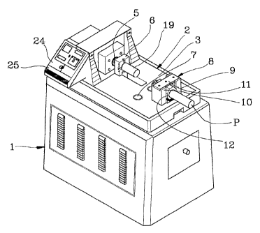
Figure 1 shows a perspective view of a multipuzpose horizontal press having a
workpiece-holder assembled according to the invention;
Figure 2 shows a perspective view of the horizontal press of Figure 1 having
the workpiece-holder that is disassembled;
Figure 3 shows a longitudinal cross section of the horizontal press of Figure
2;
Figure 4 shows in an enlarged fragmentary perspective view a longitudinal
cross section of the horizontal press of Figure 1; and
Figure 5 shows in an enlarged fragmentary cross-sectioned front view an
embodiment of the workpiece-holder according to the invention.
Referring to the drawing, a horizontal press according to the invention is
generally shown in Figure 1. A body of the press, that is surmounted by a
worktable 2, is designed as 1.
As shown in Figure 3, the worktable 2 has a superior surface 3 and an opposed
inferior surface 4.
An operating hydraulic cylinder whose rod 5 holding a work head 6 is
positioned horizontally on the worktable 2. Generally the movable part of
forming
dies such as for pressing, bending, punching and shearing operations is
connected
to the woxk head 6. This movable part of the dies is designed to co-operate
with a
fixed part of the same dies, the last one being locked in holes made on the
worktable such as those that are generally indicated as 7 in the figures. Both
the
movable and fixed parts of the forming dies are not shown in figures.
A workpiece to be subjected to a deformation work is put between the movable
part and the fixed part on the horizontal press.


CA 02459106 2004-02-26
WO 03/022481 PCT/ITO1/00465
4
According to the invention, in addition to the holes well known to the prior
art,
a through opening 70 that is better shown in Figures 2 and 4 is performed in
the
worktable 2.
The through opening 70 is made in worktable 2 in front of the work head 6 in
the opposite side with respect the rod 5 of the operating cylinder.
A bridge 8 extending over the superior surface 3 of the worktable 2 is made in
correspondence with the opening 70 in the worktable 2.
As shown in particular in Figure 1, the bridge 8 is made of a pair of uprights
9
and 10 connected by a cross member 11. The uprights 9, 10 are connected by
screws to the worktable in not shown but conventionally manner. The cross
member 11, in turn, is fixed on the uprights, as shown in Figures 1 and 4 or
alternatively is made integral with them.
The cross member 11 has in its inferior side a jaw 12 facing downward with its
concavity.
A support element generally designed as 13 is fixed under the worktable 2,
opposite to the bridge 8.
The support element 13 supports a hydraulic cylinder 14 clamping the present
workpiece-holdex. The clamping hydraulic cylinder 14 has its rod 15 extending
upward. The rod 15 in its free end has an inferior jaw 16 that is a mirror
image of
the superior jaw 12, i. e. having its a concavity facing upward.
By virtue of a preferably releasable connection of the inferior jaw I6 with
the
rod 15 of the clamping hydraulic cylinder 14, the inferior jaw 16 can slide
vertically toward the superior jaw 12 and away from it. The vertical
reciprocating
motion of the inferior jaw 16 is assured by prismatic guides as shown by a
projection 17 and a sliding recess designated as 18 in Figure 4, that is
correspondingly sized and shaped to the projection 17.
The inferior jaw 16 has usually a semicylindrical concavity with the same
radius of the superior jaw 12, in order to clamp a tubular workpiece P to be
drawn
or tapered by a matrix indicated as 19, that is assembled for this operation
onto the
work head 6, as shown in Figures 1 and 3.


CA 02459106 2004-02-26
WO 03/022481 PCT/ITO1/00465
As better shown in Figure 3, the clamping hydraulic cylinder 14 is driven
through feed/discharge conducts 20, 21 that are connected to a hydraulic unit
22,
to drive a hydraulic motor 23. There is a control board 24 of a N/C unit 25,
as
shown in Figure 3.
5 When any drawing or tapering operation is not performed by the multipurpose
horizontal press, in order to use as far as possible the worktable, the bridge
8 is
disassembled. Plates covering the through opening 70, such as those designed
as
26 in Figure 2 for example, can be applied onto the worktable. The inferior
jaw 16
can remain connected to the rod 15 of the clamping hydraulic cylinder.
Alternatively it can be disassembled therefrom.
The bridge 8 can be used with jaws having different sizes and radius.
In the operation of the clamping hydraulic cylinder 14 the thrust from the
operating cylinder through its rod 5 can be taken up by the uprights 9 and 10
of
the bridge 8.
As above mentioned, the uprights 9 and 10 and the cross member 11 can be
integral.
In Figure 5 in which parts corresponding to those in the other figures are
indicated with like ore similar reference numbers an embodiment of bridge 80,
which is connected to worktable 2 by releasable coupling means in particular
threaded coupling means, is shown.
A bridge 80 extending over the opening 70 in the worktable 2 is made of a pair
of uprights 90 and 100 connected by a cross member 110. Blocks 120, 121
connected by screws to the worktable 2 such as the one designed as 122, are
joint
laterally by welding to the uprights 90, 100. The cross member 110 is fixed on
the
uprights by screws, such as the one designed as 123.
The cross member 110 has a jaw 124 facing downward with its concavity that
is connected e.g. through a hexagonal-head socket screw 125.
A support element generally designed as 130, that is connected likely by
screws to the worktable 2, is fixed under the worktable 2, opposite to the
bridge
so.


CA 02459106 2004-02-26
WO 03/022481 PCT/ITO1/00465
6
The support element 130 supports a hydraulic cylinder 140 clamping the
present workpiece-holder. The rod 150 of the clamping hydraulic cylinder 140
has an inferior jaw 160. The vertical reciprocating motion of the inferior jaw
160
is assured by prismatic guides constituted by opposite projections 170 and a
sliding recesses 180.
The horizontal thrust applied by the operating cylinder during the drawing or
tapering operation that is not used to deform the workpiece, is discharged on
the
prismatic guides 170-180.

Representative Drawing
A single figure which represents the drawing illustrating the invention.
Administrative Status

For a clearer understanding of the status of the application/patent presented on this page, the site Disclaimer , as well as the definitions for Patent , Administrative Status , Maintenance Fee  and Payment History  should be consulted.

Administrative Status

Title Date
Forecasted Issue Date 2006-12-19
(86) PCT Filing Date 2001-09-07
(87) PCT Publication Date 2003-03-20
(85) National Entry 2004-02-26
Examination Requested 2004-05-07
(45) Issued 2006-12-19
Deemed Expired 2012-09-07

Abandonment History

There is no abandonment history.

Payment History

Fee Type Anniversary Year Due Date Amount Paid Paid Date
Registration of a document - section 124 $100.00 2004-02-26
Application Fee $200.00 2004-02-26
Maintenance Fee - Application - New Act 2 2003-09-08 $50.00 2004-02-26
Request for Examination $400.00 2004-05-07
Reinstatement: Failure to Pay Application Maintenance Fees $200.00 2004-09-13
Maintenance Fee - Application - New Act 3 2004-09-07 $100.00 2004-09-13
Maintenance Fee - Application - New Act 4 2005-09-07 $100.00 2005-08-24
Maintenance Fee - Application - New Act 5 2006-09-07 $200.00 2006-08-03
Final Fee $300.00 2006-10-03
Expired 2019 - Corrective payment/Section 78.6 $650.00 2006-10-25
Maintenance Fee - Patent - New Act 6 2007-09-07 $200.00 2007-08-24
Maintenance Fee - Patent - New Act 7 2008-09-08 $200.00 2008-08-22
Maintenance Fee - Patent - New Act 8 2009-09-08 $200.00 2009-08-31
Maintenance Fee - Patent - New Act 9 2010-09-07 $200.00 2010-09-03
Owners on Record

Note: Records showing the ownership history in alphabetical order.

Current Owners on Record
NEW TECH S.R.L.
Past Owners on Record
CAPORUSSO, ALESSANDRO
Past Owners that do not appear in the "Owners on Record" listing will appear in other documentation within the application.
Documents

To view selected files, please enter reCAPTCHA code :


To view images, click a link in the Document Description column. To download the documents, select one or more checkboxes in the first column and then click the "Download Selected in PDF format (Zip Archive)" or the "Download Selected as Single PDF" button.

List of published and non-published patent-specific documents on the CPD .

If you have any difficulty accessing content, you can call the Client Service Centre at 1-866-997-1936 or send them an e-mail at CIPO Client Service Centre.


Document
Description 
Date
(yyyy-mm-dd) 
Number of pages   Size of Image (KB) 
Abstract 2004-02-26 1 68
Claims 2004-02-26 1 45
Drawings 2004-02-26 3 85
Representative Drawing 2004-02-26 1 23
Description 2004-02-26 6 246
Cover Page 2004-05-03 1 52
Representative Drawing 2006-11-22 1 18
Cover Page 2006-11-22 1 51
Assignment 2004-05-07 1 29
Assignment 2004-02-26 4 125
PCT 2004-02-26 8 266
Fees 2004-08-24 1 30
Fees 2004-09-13 1 42
Fees 2005-08-24 1 30
Fees 2006-08-03 1 39
Correspondence 2006-10-03 1 42
Prosecution-Amendment 2006-10-25 2 95
Correspondence 2006-11-08 1 15
Correspondence 2006-11-14 1 17
Fees 2007-08-24 1 31
Fees 2008-08-22 1 30
Fees 2009-08-31 1 32
Fees 2010-09-03 1 37