Note: Descriptions are shown in the official language in which they were submitted.
CA 02459512 2004-03-04
ROTARY TOOL
FIELD OF THE INVENTION
The present invention relates to rotary tools and, more particularly, to a
drive
system for a rotary tool.
BACKGROUND OF THE INVENTION
A rotary tool, such as an impact wrench, generally includes a housing
supporting a
motor, a drive mechanism driven by the motor, an output shaft having a first
end adapted
to engage a fastener and a second end adapted to engage the drive mechanism.
In impact
wrenches, the drive mechanism generally includes a hammer member, which
periodically
impacts the output shaft, rotating the output shaft about a central axis to
hammer or drive
fasteners into or remove fasteners from a work piece.
SUMMARY OF THE INVENTION
The present invention provides a rotary tool, such as an impact wrench. In one
construction, the rotary tool includes a housing having a forward end and
supporting a
motor. The motor has a motor shaft extending axially through the housing and
defining an
axis. A frame is coupled to the motor shaft and is rotatable relative to the
housing about
the axis in response to rotation of the motor shaft. The frame defines an
interior space. A
piston is supported by the frame and is moveable axially in the interior
space. An output
shaft is supported in the forward end of the housing and is rotatable about
the axis. The
output shaft has a plurality of cams. The piston is engageable with the
plurality of cams to
intermittently deliver torque impulses to the output shaft.
CA 02459512 2004-03-04
-2-
In another construction, the output shaft includes a rearward surface and the
plurality of cams extend axially from the rearward surface. The piston
includes an axially
extending portion and the output shaft defines an aperture. The axially
extending portion
is receiveable in the aperture.
In yet another construction, the frame defines an axially extending groove and
the
piston includes a plurality of radially extending arms. The plurality of
radially extending
arms are engageable in the axially extending groove to transfer rotational
motion from the
frame to the piston.
In still another construction, the rotary tool includes a housing having a
forward
end and supporting a motor. The motor has a motor shaft extending axially
through the
housing and defining an axis. A frame is coupled to the motor shaft and is
rotatable
relative to the housing about the axis in response to rotation of the motor
shaft. The frame
has a first end and a second end and defines an interior space between the
first end and the
second end. A piston is supported in the frame and is moveable axially in the
interior
space between a retracted position, in which the piston is adjacent the second
end, and an
extended position, in which the piston is spaced a distance from the second
end. An
output shaft is supported in the forward end of the housing and is rotatable
about the axis.
The piston is engageable with the output shaft to deliver torque impulses to
the output
shaft about the axis when the piston is in the extended position.
In another construction, the rotary tool includes a housing having a forward
end
and supporting a motor. The motor has a motor shaft extending axially through
the
housing and defining an axis. A frame is coupled to the motor shaft and is
rotatable
relative to the housing about the axis in response to rotation of the motor
shaft. The frame
defines an internal space. A piston is supported in the internal space for
rotation with the
CA 02459512 2011-08-17
67363-1483
3
frame about the axis. An output shaft is supported in the forward end of the
housing
and is rotatable about the axis. One of the output shaft and the piston has a
protrusion. Another of the output shaft and the piston has a contoured recess.
The
protrusion is engageable in the recess to rotatably couple the output shaft
and the
piston. The protrusion cammingly engages the contoured recess to reciprocate
the
piston along the axis.
The present invention also provides a method of operating the rotary
tool.
Some embodiments disclosed herein related to a method of operating a
rotary tool, the rotary tool including a housing having a forward end and
supporting a
motor, the motor having a motor shaft extending through the housing and
defining an
axis, a frame coupled to the motor shaft and being rotatable relative to the
housing
about the axis in response to rotation of the motor shaft, the frame defining
an
internal space, a piston supported' in the internal space for rotational
movement with
the frame about the axis and for axial movement relative to the frame along
the axis,
and an output shaft supported in the forward end of the housing and being
rotatable
about the axis, the method comprising: engaging a fastener with the output
shaft;
rotating the housing about the axis with the motor shaft; transferring
rotational motion
from the housing to the piston; reciprocating the piston in the housing along
the axis;
cammingly engaging the output shaft with the piston; and transferring
rotational
motion from the piston to the output shaft.
Some embodiments disclosed herein relate to a rotary tool comprising:
a housing having a forward end and supporting a motor, the motor having a
motor
shaft extending axially through the housing and defining an axis; a frame
coupled to
the motor shaft and being rotatable relative to the housing about the axis in
response
to rotation of the motor shaft, the frame defining an interior space; a piston
supported
by the frame and being moveable axially in the interior space; and an output
shaft
supported in the forward end of the housing and being rotatable about the
axis, the
output shaft having a plurality of cams, the piston being engageable with the
plurality
CA 02459512 2011-08-17
67363-1483
3a
of cams to intermittently hammer the output shaft; wherein the frame houses
lubricant, and wherein axial movement of the piston creates an area of high
pressure
in the frame and an area of low pressure in the frame.
Some embodiments disclosed herein relate to a rotary tool comprising:
a housing having a forward end and supporting a motor, the motor having a
motor
shaft extending axially through the housing and defining an axis; a frame
coupled to
the motor shaft and being rotatable relative to the housing about the axis in
response
to rotation of the motor shaft, the frame defining an interior space; a piston
supported
by the frame and being moveable axially in the interior space; and an output
shaft
supported in the forward end of the housing and being rotatable about the
axis, the
output shaft having a plurality of cams, the piston being engageable with the
plurality
of cams to intermittently hammer the output shaft; wherein the frame houses
lubricant, and wherein the piston and the frame define an area of high
pressure and
an area of low pressure, the piston includes a channel, the channel
communicating
between the area of high pressure and the area of low pressure.
Some embodiments disclosed herein relate to a rotary tool comprising:
a housing having a forward end and supporting a motor, the motor having a
motor
shaft extending axially through the housing and defining an axis; a frame
coupled to
the motor shaft and being rotatable relative to the housing about the axis in
response
to rotation of the motor shaft, the frame defining an internal space; a piston
supported
in the internal space for rotation with the frame about the axis; and an
output shaft
supported in the forward end of the housing and being rotatable about the
axis, one
of the output shaft and the piston having a protrusion, an other of the output
shaft and
the piston having a contoured recess, the protrusion being engageable in the
recess
to rotatably couple the output shaft and the piston, the protrusion cammingly
engaging the contoured recess to reciprocate the piston along the axis.
Some embodiments disclosed herein relate to a rotary tool comprising:
a housing having a forward end and supporting a motor, the motor having a
motor
shaft extending axially through the housing and defining an axis; a frame
coupled to
CA 02459512 2011-08-17
67363-1483
3b
the motor shaft and being rotatable relative to the housing about the axis in
response
to rotation of the motor shaft, the frame defining an interior space; a piston
supported
by the frame and being moveable axially in the interior space; and an output
shaft
supported in the forward end of the housing and being rotatable about the
axis, the
output shaft having a plurality of cams, the piston being engageable with the
plurality
of cams to intermittently hammer the output shaft; wherein the piston includes
an
axially extending portion, and wherein the output shaft defines an aperture,
the axially
extending portion being receiveable in the aperture; wherein one of the
axially
extending portion and the output shaft includes a recess and an other of the
axially
extending portion and the output shaft includes a protrusion, the protrusion
engaging
the recess and limiting axial movement of the piston relative to the output
shaft.
Some embodiments disclosed herein relate to a rotary tool comprising:
a housing having a forward end and supporting a motor, the motor having a
motor
shaft extending axially through the housing and defining an axis; a frame
coupled to
the motor shaft and being rotatable relative to the housing about the axis in
response
to rotation of the motor shaft, the frame defining an interior space; a piston
supported
by the frame and being moveable axially in the interior space; and an output
shaft
supported in the forward end of the housing and being rotatable about the
axis, the
output shaft having a plurality of cams, the piston being engageable with the
plurality
of cams to intermittently hammer the output shaft; wherein the frame defines
an
axially extending groove, and wherein the piston includes a plurality of
radially
extending arms, at least one of the plurality of radially extending arms being
engageable in the axially extending groove to transfer rotational motion from
the
frame to the piston; wherein the output shaft includes a rearward surface, and
wherein the plurality of cams extend axially from the rearward surface, the
arms
being cammingly engageable with the plurality of cams to intermittently hammer
the
output shaft.
Some embodiments disclosed herein relate to a rotary tool comprising-
a housing having a forward end and supporting a motor, the motor having a
motor
CA 02459512 2011-08-17
67363-1483
3c
shaft extending axially through the housing and defining an axis; a frame
coupled to
the motor shaft and being rotatable relative to the housing about the axis in
response
to rotation of the motor shaft, the frame having a first end and a second end
and
defining an interior space between the first end and the second end; a piston
supported in the frame and being moveable axially in the interior space
between a
retracted position, in which the piston is adjacent the second end, and an
extended
position, in which the piston is spaced a distance from the second end; and an
output
shaft supported in the forward end of the housing and rotatable about the
axis, the
piston being engageable with the output shaft to hammer the output shaft about
the
axis when the piston is in the extended position; wherein the frame houses
lubricant,
and wherein axial movement of the piston between the retracted position and
the
extended position creates an area of high pressure in the frame and an area of
low
pressure in the frame.
Some embodiments disclosed herein relate to a rotary tool comprising:
a housing having a forward end and supporting a motor, the motor having a
motor
shaft extending axially through the housing and defining an axis; a frame
coupled to
the motor shaft and being rotatable relative to the housing about the axis in
response
to rotation of the motor shaft, the frame having a first end and a second end
and
defining an interior space between the first end and the second end; a piston
supported in the frame and being moveable axially in the interior space
between a
retracted position, in which the piston is adjacent the second end, and an
extended
position, in which the piston is spaced a distance from the second end; and an
output
shaft supported in the forward end of the housing and rotatable about the
axis, the
piston being engageable with the output shaft to hammer the output shaft about
the
axis when the piston is in the extended position; wherein the frame houses
lubricant,
and wherein the piston and the housing define an area of high pressure and an
area
of low pressure, the piston includes a channel communicating between the area
of
high pressure and the area of low pressure.
CA 02459512 2011-08-17
67363-1483
3d
Other features and advantages of the invention will become apparent to
those skilled in the art upon review of the following detailed description,
claims, and
drawings.
BRIEF DESCRIPTION OF THE DRAWINGS
The present invention is further described with reference to the
accompanying drawings, which show constructions of the present invention.
However, it should be noted that the invention as disclosed in the
accompanying
drawings is illustrated by way of example only. The various elements and
combinations of elements described below and illustrated in the drawings can
be
arranged and organized differently to result in constructions which are still
within the
spirit and scope of the present invention.
In the drawings, wherein like reference numerals indicate like parts:
Fig. 1 is a side view, partially in section, of a rotary tool embodying the
present invention.
Figs. 2A and 2B are side views, partially in section, of a portion of a
rotary drive system of the rotary tool shown in Fig. 1.
Fig. 3 is an exploded view, partially in section, of the portion of the
rotary drive system shown in Figs. 2A and 2B.
Fig. 4 is a side view, partially in section, of a housing of the rotary drive
system shown in Figs. 2A and 2B.
CA 02459512 2004-03-04
-4-
Fig. 5 is a side view, partially in section, of a frame of the rotary drive
system
shown in Figs. 2A and 2B.
Figs. 6A-6D illustrate a piston of the rotary drive system shown in Figs. 2A
and
2B.
Figs. 7A-7D illustrate an output shaft of the rotary drive system shown in
Figs. 2A
and 2B.
Figs. 8A-8D are side views of the portion of the rotary drive system shown in
Figs.
2A and 2B operating in a forward mode.
Figs. 9A-9D are sectional views of the portion of the rotary drive system
shown in
Figs. 2A and 2B operating in a forward mode.
DETAILED DESCRIPTION
As used herein and in the appended claims, the terms "upper", "lower",
"first",
"second", "third", "forward", and "rearward" are used herein for description
only and are
not intended to imply any particular orientation, order, or importance.
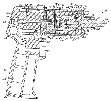
Fig. 1 illustrates a rotary tool 10, such as, for example, an impact wrench
embodying aspects of the present invention. The rotary tool 10 includes a
housing 12
having a forward portion 16 and a rearward portion 18, an operator's grip or
handle 20, a
motor 22 (e.g., an air motor) having a motor shaft 24, a trigger 26 operably
coupled to the
motor 22 to control motor speed, and a rotary drive system 28. The motor shaft
24 defines
a central axis A, which extends axially through the rotary tool 10.
The handle 20 includes an air channel 32 having an inlet 34. In some
constructions
(not shown), the air channel 32 includes seals (e.g., O-rings, washers, etc.),
filters (e.g., air
strainers), and valves (e.g., spring-operated valves) for controlling air
quality into and
airflow through the rotary tool 10. Additionally, in some constructions (not
shown), the
CA 02459512 2004-03-04
-5-
air channel 32 includes a throttle valve (not shown) that is operably
connected to the
trigger 26 for controlling the flow of air through the air channel 32, the
operating speed of
the rotary tool 10, and/or the torque generated by the rotary tool 10. Also,
in rotary tools
having forward and reverse modes, a reverse valve (not shown) may be
positioned
5 along the air channel 32 to direct air flow through the motor 22 in either
of two directions
(i.e., forward and reverse).
The rearward portion 18 of the housing 12 defines a cavity 36 surrounding the
motor 22. The motor shaft 24 extends through the cavity 36 along the central
axis A and is
supported by bearings 38, 40 for rotation relative to the housing 12.
Pressurized air from
10 the air channel 32 enters the rearward end of the cavity 36 and travels
across the motor 22,
causing the motor 22 to rotate about the central axis A in a conventional
manner. In some
constructions, the cavity 36 is sealed (e.g., the cavity includes O-rings,
washers, valves,
etc.) to prevent unintended air exchange with the atmosphere. One having
ordinary skill in
the art will appreciate that while one type of air motor has been described
herein and is
shown in the figures, other types of air motors (not shown) could also or
alternately be
used. In other constructions (not shown), electric motors (not shown) could
also or
alternately be used.
Fasteners (not shown) extend through the forward portion 16 of the housing 12
and
into bores 42 located in the rearward portion 18 of the housing 12, coupling
the forward
and rearward portions 16, 18 of the housing 12. A seal (e.g., an O-ring, a
washer, etc.) 46
is arranged between the forward and rearward portions 16, 18 to prevent
airflow into or
out of the housing 12 between the forward and rearward portions 16, 18.
With reference to Figs. 1, 2A, 2B, 3, 5, and 8A-8D, the rotary drive system 28
includes a flywheel or frame 44 supported in the forward portion 16 of the
housing 12 for
rotation about the central axis A. The frame 44 is a substantially cylindrical
member
CA 02459512 2004-03-04
-6-
having a forward surface 48, a rearward surface 50 substantially parallel to
the forward
surface 48, and a circumferential wall 52 extending therebetween. Together,
the
circumferential wall 52 and the interior surface of the forward portion 16 of
the housing
define a space 54, which accommodates rotational movement of the frame 44
relative to
the forward portion 16 of the housing 12.
With reference to Fig. 1, the rearward face 50 defines a recess 56 having a
number
of splines 60 extending radially into the recess 56. A forward end of the
motor shaft 24
includes splines 64, which matingly engage corresponding splines 60, operably
coupling
the frame 44 and the motor shaft 24 for concurrent rotation about the central
axis A in
either a forward (e.g., clockwise) or rearward (e.g., counterclockwise
direction).
As shown in Figs. 1, 2A, 2B, 3, 5, and 8A-8D, the forward and rearward
surfaces
48, 50 of the frame 44 define an internal space 67 housing a quantity of
lubricant (not
shown). The interior surface 66 of the circumferential wall 52 includes first
and second
shoulders 68, 69 that extend radially into the internal space 67. As shown in
Fig. 5, the
area of the internal space 67 rearward the second shoulder 69 has a first
diameter D1, the
area between the first and second shoulders 68, 69 has a second diameter D2,
and the area
forward the second shoulder 69 has a third diameter D3. As shown in Figs. 2A,
3, and 5,
axial grooves 70 extend into the circumferntial surface 52 between the first
and second
shoulders 68, 69. In some constructions, the frame 44 includes two axial
grooves 70
spaced approximately 180 degrees apart. In other constructions (not shown),
the frame 44
may include one, three, or more axial grooves 70 and the axial grooves 70 can
be arranged
in any of a number of configurations and orientations.
The forward surface 48 defines a forward opening 71 communicating with the
interior space 67. A cover 72 is coupled to (e.g., threaded into, clamped
onto, or otherwise
fastened to) the forward surface 48 to seal the internal space 67. In the
illustrated
CA 02459512 2004-03-04
-7-
construction, the cover 72 is threaded into forward surface 48 and a seal 74
(e.g., an 0-
ring, a washer, etc.) is clamped between the second shoulder 69 and the cover
72 to
prevent fluid exchange between the internal space 67 and the space 54. The
cover 72 also
defines an internal opening 76 opening along the central axis A and including
a seal 78.
A bleed line 80 extends through the frame 44 for conveying lubricant from one
portion of the internal space 67 to another portion of the internal space 67
(as described
below). In the illustrated construction (see Figs. 2A, 3, and 5), the bleed
line 80 includes
an axial channel 82 extending axially through the frame 44, and a radial
channel 84 that
extends radially through the frame 44 and intersects the axial channel 82. As
shown in
Fig. 2B, plugs 86 (e.g., a ball bearing, a threaded plug, etc.) seal two ends
of the axial
channel 82. A first opening 88 of the axial channel 82 communicates with the
internal
space 67 and a second opening 90 of the axial channel 82 intersects an end of
the radial
channel 84. An opening 83 of the radial channel 84 communicates with the
internal space
67. A valve (e.g., a needle valve) 96 is positioned in the radial channel 84
and is operable
to selectively restrict and/or prevent fluid flow through the bleed line 80
(as explained in
greater detail below). An operator and/or the manufacturer can increase or
decrease fluid
flow through the bleed line 80 by inserting a tool (e.g., a screwdriver, a
wrench, etc.)
through an opening 98 (shown in Figs. 1, 2B, 3, and 4) in the forward portion
16 of the
housing 12 to adjust the position of the valve 96.
As shown in Figs. 1, 2A, 2B, and 8A-8D, an output shaft or anvil 100 extends
through the cover 72 and is supported in the forward portion 16 of the housing
12 by
bushing 102 for rotation about the central axis A. However, in other
constructions (not
shown), other support structure, such, as for example, bearings can also or
alternately
support the output shaft 100. Additionally, in other constructions (not shown)
the output
CA 02459512 2004-03-04
-8-
shaft 100 can be arranged to rotate about a second axis that is substantially
parallel, or
alternatively, at an angle relative to the central axis A.
With reference to Figs. 1, 2A, 2B, 3, 7A, 7B, 7D, and 8A-8D, the output shaft
100
is substantially cylindrical and includes a forward or tool engaging end 104
that is adapted
to support a fastener (e.g., a bolt, a screw, a nut, etc.) and/or a fastener
engaging element
(e.g., a socket). A base portion 106 of the output shaft 100 extends into the
internal space
67 and includes two rearwardly extending cams 108. In other constructions (not
shown),
the base portion 106 can include one, three, or more cams 108. As shown in
Figs. 1 and
2B, the base portion 106 rests against the second shoulder 69. Additionally,
in some
constructions, the diameter of the base portion 106 is substantially similar
to the second
diameter D2 and the base portion 106 closely engages the circumferential wall
52 to
prevent lubricant from leaking between the second shoulder 69 and the base
portion 106.
The base portion 106 also defines an aperture 110 that extends axially into
the output shaft
100 along the central axis A.
As shown in Figs. 1, 2A, 2B, and 3, in some constructions, seals 112 (washers,
0-
rings, etc.) are positioned between the cover 72, the base portion 106 and/or
the
circumferntial surface 52 to prevent lubricant from exiting the internal space
67 via the
forward opening 71. Additionally, in some constructions, friction-reducing
members 113
(e.g., bearings, low-friction washers, etc.) are positioned between the cover
72 and the
base portion 106.
A piston (shown in Figs. 1, 2A, 2B, 3, 6A-6D, and 8A-8D) 114 includes a first
end
116 and a second end 118 and is supported in the internal space 67 for
rotational
movement with the frame 44 about the central axis A and for reciprocating
movement
relative to the frame 44 along the central axis A. The first end 116 of the
piston 114 is
substantially cylindrical and is rotatably received in the aperture 110 at the
base 106 of the
CA 02459512 2004-03-04
-9-
output shaft 100. A notch 120 extends circumferentially around the first end
116. As
shown in Figs. 3, 6A, and 6B, a forward end 122 of the notch 120 is contoured
and
includes a protrusion 147. A fastener (e.g., a set screw, a key, a snap ring,
etc.) and/or a
radially extending protrusion 126 extends through an opening 128 (shown in
Fig. 3) in the
output shaft 100 and engages the notch 120 on the first end 116 of the piston
114 to
slidably and rotatably couple the output shaft 100 and the piston 114.
Together, the notch
120 and the fastener 126 limit axial movement of the piston 114 along the
output shaft
100. More particularly, the piston 114 is moveable along the central axis A
between a
fully retracted position (shown in Figs. 8A and 9A) and a fully extended
position (shown
in Figs. 8B and 9B) and the distance between the fully retracted and fully
extend positions
is approximately equal to the axial length of the notch 120. Additionally, the
mating
engagement of the fastener 126 and the notch 120 facilitate relative
rotational motion
between the piston 114 and the output shaft 100.
The second end 118 of the piston 114 is substantially cylindrical and has a
diameter D4 (see Figs. 6A, 6C, and 6D), which is substantially similar to the
first diameter
D1. More specifically, the second end 118 closely engages the circumferential
wall 52,
preventing or reducing the flow of lubricant between the circumferential wall
52 and the
second end 118 of the piston 114.
As shown in Figs. 2A, 3, 6A, 6D, 8A-8D and 9A-9D, arms 132 (two arms 132 are
shown) extend radially from the piston 114 between the first and second ends
116, 118. In
other constructions (not shown), the piston 114 can include one, three, or
more arms 132.
The arms 132 engage axial grooves 70, facilitating the transfer of rotational
motion from
the frame 44 to the piston 114. Additionally, as described below, the arms 132
are
moveable along the axial grooves 70 to facilitate axial movement of the piston
114 relative
to the frame 44. The mating engagement between the arms 132 and the axial
groves 70
CA 02459512 2004-03-04
-10-
also prevents the piston 114 from pivoting about the central axis A relative
to the frame
44.
As shown in Figs. 1 and 8A-8D, the second end 118 of the piston 114 divides
the
internal space 67 into a first or forward chamber 134 and a second or rearward
chamber
136. Lubricant is moveable between the first and second chambers 134, 136
along the
bleed line 80, or alternatively, along a channel 138 (see Fig. 6D). As shown
in Figs. 3 and
6D, channel 138 extends axially through the second end 118 of the piston 114
and radially
outwardly through a central portion of the piston 114 between the arms 132,
fluidly
connecting the first and second chambers 134, 136.
As shown in Figs. 1, 2B, and 3, valve 96 is positioned along the bleed line 80
to
control the flow of lubricant between the first and second chambers 134, 136.
As shown
in Figs. 1, 2A, 2B, 3, 6A-6D, and 8A-8D, feet 140 extend axially from the
second end 118
of the piston 114 and support valve 142. As explained in greater detail below,
valve 142 is
operable to control the flow of lubricant along channel 138. In the
illustrated construction,
valve 142 is a ball valve. However, in other constructions (not shown), other
known
valves can also or alternatively be used to control the flow of lubricant
through channel
138.
During operation of the rotary tool 10, the tool engaging end 104 (or a
fastener
engaging element coupled to the tool engaging end 104) is positioned to
matingly engage a
fastener (e.g., a nut, a bolt, a screw, etc.). To tighten the fastener or
thread the fastener
into a work piece (not shown), the rotary tool 10 is operated in a forward
mode and to
loosen the fastener or unthread the fastener from the work piece, the rotary
tool 10 is
operated in a reverse mode. Figs. 8A-8D and 9A-9D and the following
description refer to
operation of the rotary tool 10 in the forward mode. However, one having
ordinary skill in
the art will appreciate that the rotary tool 10 of the present invention can
also or alternately
CA 02459512 2004-03-04
-11-
be operated in a reverse mode and that operation of the rotary tool 10 in the
reverse mode
is substantially similar to operation of the rotary tool 1.0 in the forward
mode.
To initiate operation of the rotary tool 10, an operator depresses the trigger
26,
causing power in the form of compressed air or electricity to energize the
motor 22 and to
rotate the motor shaft 24 in a forward direction (represented by arrow 146 in
Figs. 8A-8D
and 9A-9D) about the central axis A. The motor shaft 24 transfers rotational
motion to the
rotary drive system 28 via the mating engagement of splines 60, 64.
With reference first to Figs. 8A and 9A, the piston 114 is in a fully
retracted
position (i.e., the piston 114 is in a rearward-most position in the internal
space 67), and
the fastener 126 engages a rearward-most position in the notch 120.
Additionally, the
valve 142 is in a closed position, preventing lubricant from moving through
the channel
138 between the forward and rearward chambers 134, 136. Also, when the piston
114 is in
the fully retracted position, the pressure of the lubricant in the forward and
rearward
chambers 134, 136 is approximately equal.
With reference to Figs. 8B and 9B, as the motor 22 begins to rotate the frame
44
about the central axis A, the frame 44 transfers rotational motion to the
piston 114 via the
mating engagement between the arms 132 and the grooves 70. The notch 120 on
the first
end 116 of the piston 114 travels along the fastener 126 as the piston 114
rotates about the
central axis A. As the contoured end 122 of the notch 120 travels across the
fastener 126,
the fastener 126 pulls the piston 114 forward along the central axis A toward
the base
portion 106 of the output shaft 100. In this manner, the piston 114
simultaneously rotates
about the central axis A in the forward direction 146 and moves forward along
the central
axis A toward the output shaft 100. As the piston 114 is pulled forward by the
engagement between the fastener 126 and the contoured end 122 of the notch
120, valve
142 moves from a first or closed position to a second or open position. In
particular, as the
CA 02459512 2004-03-04
-12-
piston 114 is pulled forward, the pressure in the forward chamber 134
increases. The
increased pressure in the forward chamber 134 forces the ball portion of valve
142
rearwardly with respect to the second end 118 of the piston 114, allowing
lubricant to
move through the channel 138 from the forward chamber 134 to the rearward
chamber
136.
As the piston 114 continues to rotate about the central axis A, the fastener
126
rides along the contoured end 122, moving the piston 114 forward along the
central axis A
to a forward-most position (shown in Figs. 8B and 9B). When the piston 114 is
in the
forward-most position, forward portions of the arms 132 contact the base 106
of the output
shaft 100. In the illustrated construction, the contoured end 122 of the notch
120 includes
protrusion 147. In this construction, each time the piston 114 rotates about
the central axis
A, the fastener 126 engages the protrusion 147 once. More particularly, each
time that the
piston 114 rotates about the central axis A, the engagement between the
protrusion 147
and the fastener 126 causes the arms 132 to contact the cams 108. In other
constructions
(not shown), the notch 120 can have two, three, or more protrusions 147 for
causing the
arms 132 to contact the cams 108 two or more times each time the piston 114
rotates about
the central axis A.
With reference to Figs. 8C and 9C, as the piston 114 moves forward along and
rotates about the central axis A, the arms 132 are rotated into engagement
with the cams
108 on the base 106 of the output shaft 100. The impact between the arms 132
and the
cams 108 transfers an impulse or force from the piston 114 to the output shaft
100, causing
the output shaft 100 to rotate about the central axis A in the forward
direction 146. The
impact between the arms 132 and the cams 108 also causes the piston 114 to
rebound a
relatively short distance rearwardly along the central axis A and to rotate a
relatively short
distance about the central axis A in the reverse direction 148. The rearward
motion of the
CA 02459512 2004-03-04
-13-
piston 114 causes an increase in pressure in the rearward chamber 136. More
particularly,
in some constructions, the pressure in the rearward chamber 136 reaches
between 1000 psi
and 4000 psi (e.g., 3000 psi). After the initial impact, the forward rotation
of the frame 44
about the central axis A, and in some cases, the increase in pressure in the
rearward
chamber 136, causes the arms 132 to remain in contact with the cams 108 to
transfer
rotational energy to the output shaft 100.
Additionally, after the impact between the cams 108 and the arms 132, the
piston
114 begins to move rearwardly, disengaging the arms 132 from the cams 108.
More
particularly, as shown in Figs. 8D and 9D, as the piston 114 moves rearwardly
along the
central axis A, the arms 132 are moved rearwardly away from the cams 108 so
that the
arms 132 pass the second side of the cams 108 without contacting the cams 108.
As the piston 114 continues to rotate about the central axis A, the pressure
difference between the forward and rearward chambers 134, 136 forces lubricant
from the
rearward chamber 136, through bleed line 80, past valve 96, and into the
forward chamber
134. In this manner, the pressure in the rearward chamber 136 is reduced,
allowing the
piston 114 to move axially to the rearward-most position. Lubricant continues
to move
along the bleed line 80 from the rearward chamber 136 to the forward chamber
134 until
the pressure of the forward and rearward chambers 134, 136 is approximately
equal. In
the illustrated construction, the pressure in the forward and rearward
chambers 134, 136 is
approximately equal when the arms 132 pass across the cams 108.
Once the piston 114 returns to the rearward-most position, the piston 114
continues
to rotate with the frame 44 about the central axis A until the engagement
between the
notch 120 and the fastener 126 causes the piston 114 to move forwardly along
the central
axis A. In the illustrated construction, the piston 114 rotates approximately
200 degrees
about the central axis A before the fastener 126 engages the protrusion 147 to
re-initiate
CA 02459512 2004-03-04
-14-
forward motion of the piston 114. However, as explained above, in other
constructions
(not shown), the notch 120 can include two, three, or more protrusions 147. In
these
constructions, the piston 114 can rotate less than 200 degrees before the
mating
engagement between the fastener 126 and one of the protrusions 147 causes the
piston 114
to move forwardly along the central axis A.
The constructions described above and illustrated in the drawings are
presented by
way of example only and are not intended as a limitation upon the concepts and
principles
of the present invention. As such, it will be appreciated by one having
ordinary skill in the
art, that various changes in the elements and their configuration and
arrangement are
possible without departing from the spirit and scope of the present invention
as set forth in
the appended claims.
For example, one having ordinary skill in the art will appreciate that the
size and
relative dimensions of the individual parts of the rotary tool can be changed
significantly
without departing from the spirit and scope of the present invention.
As such, the functions of the various elements and assemblies of the present
invention can be changed to a significant degree without departing from the
spirit and
scope of the present invention.