Note: Descriptions are shown in the official language in which they were submitted.
CA 02459625 2004-03-04
Screen for cleaninq a fibre suspension
The invention relates to a screen for cleaning a fibre suspension
according to the preamble of patent claim 1.
s Screens are machines used in the paper industry to clean a pulp
suspension comprising water, fibres, and dirt particles. Here a feed flow
runs through a screening device, where the accept flow, consisting of
water and fibres, flows through the screen. A partial flow, known as the
reject and consisting of water, fibres, and dirt particles, is generally
~o removed at the opposite end to the feed flow. Thus, the solids particles
present in the liquid are separated from one another in the screens. By
contrast, in filtration processes the liquid is separated from the solids.
In general, a screen of this type is rotationally symmetrical and consists of
15 a housing with a feed device mounted at a tangent, a cylindrical screen
basket, normally with perforations or vertical slots, and a rotating rotor.
The purpose of the rotor is to keep the screen slots clear, achieved by the
vanes rotating close to the screen surface. The accept is collected in a
so-called accept chamber, which often has a conical design, and drawn
20 off from here in radial direction. The reject flow is generally brought to
a
reject chamber, which is usually annular, located at the opposite side of
the screen basket to the inlet, and drawn off from here at a tangent .
A screen of this type is known, for example from US 4,268,381.
Other screens known are described in, for example, EP 1 122 358 A2,
25 EP 1 124 002 A2, and EP 1 124 003 A2.
2443A 1
CA 02459625 2004-03-04
In the screens according to EP 1 122 358 A2, EP 1 124 002 A2, and
EP 1 124 003 A2, the following measures are implemented, particularly in
order to improve flow conditions:
~ An additional screen basket is provided in the feed area for pre-
screening.
~ In the feed area between the pipe socket and the freely accessible
end of the rotor there is a stationary mounting, particularly a cone,
truncated cone, hemisphere, spherical segment, spherical segment
between two parallel circles, paraboloid, or a hyperboloid of two
o sheets.
~ The accept chamber is designed as twin cones, widening in flow
direction of the pulp suspension and tapering again from the mouth of
the accept outlet in a conical shape towards the reject outlet.
In these known screens the rotor is designed for even flow onto the
~5 screen and is parabolic in shape so that the axial flow speed inside the
screen basket remains constant at an assumed uniform flow through the
screen basket. As an alternative, a cone shape can be used to come
closer to the parabolic shape of the rotor.
It is also known that screens can be designed as mufti-stage units,
2o comprising several separation stages one after another:
The screens known from the state of the art, however, still hold
disadvantages. In particular, the flow conditions at the reject outlet leave
much to be desired.
The present invention aims to provide a screen in which a further
25 improvement can be attained in the flow conditions and thus, a reduction
in the energy applied, while increasing production and dirt separation.
2443A 2
CA 02459625 2004-03-04
According to the present invention the problem is solved with a screen
according to patent Claim 1. Other preferred designs of screen according
to the invention are described in the sub-claims.
The screen according to the invention is characterised by the reject outlet
being located in the vicinity of the maximum rotor diameter and by one or
several devices to interrupt the axial flow being located in the vicinity of
the maximum rotor diameter.
In the following, the term "devices" (plural) is used, relating also to
screens
according to the invention which have only one device to interrupt axial
flow.
Depending on their origin and type (recycled fibres, fresh fibres, etc.),
pulps contain differing amounts of dirt particles. To ensure stable screen
operations, certain minimum amounts of carrier medium (reject amounts)
must be set as a function of the dirt and flake content, and of the
suspension's rheological characteristics.
It has proved favourable to mount devices to interrupt the axial flow at the
same height as the maximum rotor diameter in order to guarantee stable
screen operations.
The devices to interrupt axial flow can be mounted at the housing of the
2o separation unit or at the screen basket andlor at the rotor of the screen.
Thus, a design in which devices to interrupt the axial flow are provided on
both sides (i.e. both at the housing and at the rotor) is also possible.
The devices should preferably be one or several axial flow interruption
rings. Depending on its design, the flow interruption ring can either be
continuous or in the form of individual segments, or have gaps.
2443A 3
CA 02459625 2004-03-04
The flow interruption ring {or flow interruption rings) can be of adjustable
design, such that the size of the opening created by the flow interruption
ring for the reject can be modified.
The flow interruption ring can be of adjustable design, for example in the
s same way as an iris diaphragm. In addition, the flow interruption ring can
be adjustable statically (e.g. in the form of statically adjustable ring
segments).
The outer diameter of a flow interruption ring on the rotor side preferably
has a toothed profile.
~o A further preferred configuration of the screen according to the invention
is
characterised by at least one feed for dilution water being located in the
vicinity of the reject outlet, particularly directly below it.
As a result, the reject leaving the screen is diluted with water. This
dilution
is favourable particularly in a multi-stage screen configuration where the
~ 5 reject from one stage is also the feed to the following stage.
One or more feed points can be provided for dilution water, which can be
located at the housing of the separation unit or at the screen basket
and/or at the rotor. If a feed for dilution water is located at the rotor,
this
feed is supplied preferably through a pipe mounted inside the rotor.
2o The feed point - if necessary, several - for dilution water can be oriented
such that dilution water can enter in rotor running direction and/or in the
opposite direction to rotation of the rotor.
Thus, the rotating movement of the pulp suspension can be reduced. By
causing turbulence in the suspension, loosening of the suspension can be
25 improved.
2443A Q,
CA 02459625 2004-03-04
In a further preferred configuration of the screen according to the
invention, at least one feed for dilution water is coupled to a device for
interrupting the axial flow. For example, the feed of dilution water can
protrude into the area between housing and rotor and thus, serve as~ a
device for interrupting the axial flow.
Particularly in mufti-stage screens, thickening of the suspension takes
place on the one hand in the inflow area to the screen surface as the
suspension flows between the first and the fins( screening stage, and on
the other hand, the fake content becomes more concentrated.
o In order to maintain the screening effect, the suspension consistency, as
described above, is set by means of intermediate dilution. It has proved
favourable to counteract this concentration of the flake content by
inserting a deflaking unit.
Thus, the separating unit of the screen according to the invention should
preferably contain a deflaking unit. Advantageously, the deflaker should
take the form of one or several rings mounted on the housing or screen
basket and/or on the rotor. The shape of the mountings used
corresponds to models that are already known in themselves, while
additional hydraulic guiding elements can be included in order to set
2o differential pressures.
The screen according to the invention can preferably comprise two or
more separation units located one after another in a manner already
known, where all separation units have one common rotor, which has a
parabolic or parabolic segment shape for each separation unit, adapted to
2s the flow conditions in the separation unit in each case.
2443A
CA 02459625 2004-03-04
The height of each separation unit should preferably be at least twice the
sum of the heights of all separation units adjoining the separation unit in
question, i.e. in a screen with three separation units, the height of the
first
stage is at least 2/3 the overall height of the unit and the height of the
second stage is at least 2/9 of the overall height.
Each separation unit of a multi-stage screen according to the invention
should preferably contain one or more devices to interrupt the axial flow,
as described above, in the vicinity of the maximum diameter.
Similarly, it is preferable to have at least one inlet for dilution water in
each
o separation unit in the vicinity of the reject outlet or underneath it.
In a multi-stage screen, the feed for dilution water can be located in the
lower delimitation of the rotor segment of a separation unit so that the
dilution water is discharged into the space beneath the rotor segment (and
thus into the vicinity of the reject outlet or the area below it). As an
~s alternative or additionally, the feed for dilution water can be mounted in
the upper part of the rotor segment of the following separation unit.
In a multi-stage screen according to the present invention with at least
three separation units, a minimum of one deflaking unit should preferably
be provided, particularly at the transition from the second to the third
2o separation unit.
In addition to the features described above, the screen according to the
invention should preferably contain one or several features of the screens
described in EP 1 122 358 A2, EP 1 124 002 A2, and EP 1 124 003 A2.
Preferred configurations of the screen according to the invention are
2s explained in more detail below and based on the illustrations.
2443A
CA 02459625 2004-03-04
These illustrations show:
Figure 1 a view of a screen according to the state of the art
Figure 2 a view of a multi-stage screen according to a preferred
configuration of the present invention
s Figure 3 an enlarged section of a reject outlet from the screen
according to Figure 2
Figure 4 an enlarged section of an alternative design of a reject outlet
The screen according to Figure 1 comprises, in a way already known, a
o feed branch 2, through which a pulp suspension if fed for cleaning
purposes. In the feed area, a mounting 3 is provided, which is shown
here as a truncated cone. The pulp suspension enters the space between
the parabolic rotor 4 and the screen 5 and is conveyed through the screen
into the accept chamber 6. The housing of the accept chamber is
designed as a double cone in this configuration and in a way which is
generally known. The accept outlet is marked with reference number 7.
The reject is removed through a reject outlet 8.
fn Figure 2, those devices or parts of devices that are identical to the
configuration which is state of the art and shown in Figure 1 are marked
2o with the same reference numbers. In the preferred configuration of a
screen according to the invention and as shown in Figure 2, the screen 1
consists of three separation units 1', 1" and 1"'.
2443A 7
CA 02459625 2004-03-04
The three separation units 1', 1" and 1"' have one common rotor, whose
sections 4', 4" and 4"', respectively, adapted to the flow conditions in the
corresponding separation unit, are parabolic or have the shape of a
truncated paraboloid. As an alternative, the sections of the rotor can ~Iso
be shaped similar to a truncated cone or a parabola.
Each separation unit has a reject outlet (9', 9" and 9"'). The reject from
the first and second separation units is thus also the feed to the next
separation unit in each case. The reject from the third and final
separation unit is drawn off through the reject outlet 8.
o In Figure 2, a pipe for dilution water mounted inside the rotor is marked 10
and the outlets from the pipe will be described in more detail below.
A deflaking unit 13 is provided at the transition from the second to the third
separation unit.
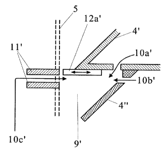
Figures 3 and 4 show preferred configurations of a reject outlet (in this
5 case reject outlet 9') in an enlargement of the section marked with a chain-
dot line in Figure 2.
According to the configuration shown in Figure 3, an adjusting ring 12 a' is
mounted at the lower end of the rotor section 4'. The adjusting ring can
have an adjustable mounting, as explained above, e.g, in the shape of an
2o iris diaphragm (indicated by the double arrow). The outer diameter of the
adjusting ring or ifs segments should preferably have a toothed profile.
With the adjustable ring 12a', the axial throughput can be controlled by
means of the reject outlet 9'.
2443A $
CA 02459625 2004-03-04
Furthermore, in the configuration according to Figure 3, feed points for
dilution water 10a', 10b', and 10c' are provided on the housing, as well as
at rotor sections 4' and 4'° in the vicinity of the reject outlet 9'
and beneath
it.
The feed point 10a' is located in the lower delimitation of the rotor
segment 4' of the first separation unit 1'. The feed point 10b' is placed in
the upper section of the rotor segment 4" of the second separation unit 1".
The feed points 10a' and 10b' can be supplied through a pipe 10 (see
Figure 2) mounted inside the rotor.
o The feed point 10c', for example, is located in the vicinity of a flange 11
between the first separation unit 1' and the second separation unit 1" and
is supplied through a pipe not shown in this illustration.
With the feed pipes for dilution water 10a', 10b' and 10c', the consistency
of the pulp suspension flowing to-the next separation unit can be
controlled effectively.
The configuration of the reject outlet 9' shown in Figure 4 differs from the
configuration shown in Figure 3 in that a flow interruption ring 12b' is
mounted on the housing in addition to the adjusting ring 12a'. The
housing side feed 10c' for dilution water is also located in the flow
interruption ring 12b', i.e. the feed for dilution water and the flow
interruption ring are coupled to one another. Of course, the configuration
in Figure 4 can also include additional feed lines for dilution water at the
rotor, as shown in Figure 3.
2443A