Note: Descriptions are shown in the official language in which they were submitted.
CA 02459649 2004-03-04
ASTEI3TIS BEHRING Gi~~H 2003/~IOO$ (A68)
Transfer device, :ln particular for meds.r~a3 fluids
The invention relates to a transfer device, in
particular for medical fluids, with a housing, with a
first needle-shaped or mandril-shaped piercing element
mounted in the housing, with a second needle-shaped or
mandril-shaped piercing element mounted in the housing,
the two piercing elements pointing away from one
another ar~d havinc-; flaw charnels, a:nd moreover with a
slide which is arranged between the two piercing
elements, is mounted in t:he hou.~ir~g and can be
displaced with respect to the piercing elements such
that, in a first position of displacemerat of the slide,
a flow connection is established between the two
piercing elements, and, in a second position of
displacement of the slide, a flow connection is
established between one of the piercing elements and a
lateral opening of the housing.
In medical technology, it as necessary to transfer
fluid from a first container, in particular a vial, to
a second contain:=r, in particular a vial, which
25~ contains a substance that is to be dissc>lved. To do so,
a transfer device is inserted with the piercing
elements, which are needle-shaped or rnandril-shaped
elements, into the closure stoppers respectively
sealing the two containers and made of rubber or the
like, i.e. the closure stoppers are pierced by the
piercing elements, such that, in the first position of
displacement of the slide, a flow connection is created
between the two co:r~tainers via the flow channels. The
transfer of the fluid is guaranteed in particular by
the fact that where is a vacuum in the inside of the
container contain~.ng the substance to :rye dissolved. If
further flow channels are routed through the piercing
elements, these can serve to ensure pressure
compensation between the two containers, if there is no
CA 02459649 2004-03-04
2
vacuum in said container. ~'he transfer of the fluid
takes place with th.e container containing the fluid
:located at the top, so that the fluid can pass into the
container located underneath and ho:Ldi:~g the substance
to be dissolved. P,fter the substance has dissolved, the
slide is moved to the second position of displacement,
and the connect-on between the ivwo ccntainers is thus
blocked off. The transfer device is then turned so that
the container with the dissolved substance is at the
top. Since the piercing element inserted into the
stopper of the container located at the top is now in
flow connection with a lateral rernoval channel, the
dissolved fluid c~~n be remoz°ed from th.e vial by means
of a syringe.
Such a transfer device is not only suitable for
dissolving a medycament, ~~-at also :nor mixing two
fluidsP for transferring a gas, etc.
A transfer device of the type mentioned at the outset
is known from ~P 0 521 460 A~. There, the two piercing
elements are prov~_ded with a fluid channel and also
with an air channel. A slide cooperates with the fluid
channel and serves directly to receive t:he syringe cone
;~5~ of a syringe. The slide is displaceabiF= such that, in
the fi_~st position of displacement of_ the slide, the
fluff d chanx~el is freely accessible . A lip valve is
fitted into the removal chanrsel of the slide. This lip
valve ensures that fluid does noi~ escape to the
3G outside, particular°ly when there is no syringe fitted
in the slide. In the second position of d=_splacement of
the slide, a forwardly protruding shoulder of the slide
closes off the access to the flow channel of that
piercing element fitted into the container which
35 originally received the fluid fog: dissolving the
substance. On account of this position of the slide,
the dissolved subsv~ance can be removed from the other
container, past the lip valve, by means of the syringe.
To guide the slide in the housing, it has a cylindrical
CA 02459649 2004-03-04
- 3 -
attachment which cooperates with a corresponding
cylindrical attachment of the housing'.
A disadvantage of this transfer device is its
complicated design . Thus, it is necE~ssar;~r to provide a
specially designed valve wit~x which ~to equip the slide.
Accordingly, the structure of the slide is complicated,
quite apart from the requ?_rement that it have the
projection with which the fluid channel can be blocked
off. During handling, a particular disadvantage is that
the syringe is connected to a movable part, namely the
slide. There is therefore a danger of the slide being
inadvertently mo~;eed into the first position of
displacement upon ~=emoval of the fluid.
US 6,379,340 Bl discloses a transfer device for medical
fluids in which, instead of a slide, use is made of a
part mounted rotatably in a housing. In a first
position of rotation, the pa~~t forms a flow connection
between two piercing elements and, in a second position
of rotation, it forms a flow connection between one of
the piercing elements and a lateral removal channel of
the rotatable element. The rotatabeLe element has a
connector into which t:ne attachment piece of a syringe
25' can be inserted. The structure of this tx:ansfer device
and its assembly are very complicated. Furthermoref
handling is unsatisfactory since, because the rotatable
part has to be turned for transferring the transfer set
to the operating positions, it is generally unclear to
the user which operative position tale transfer device
is in and in which direction the part is to be turned.
A transfer device with a piercing element is described
in US 6,378,714 B1. A vial is closed ofY with a rubber
stopper, and a housing is placed onto the closed vial:
The housing receives a slide with piercing element.
When the cone of a syringe is inserted into the
housingF the slide guided in the housir_g is displaced
and the piercing element pierces through the seal of
CA 02459649 2004-03-04
_ LI~
the vial. The fluid is able to flow through a channel
formed. in the piercing element and ire the slide. This
transfer device does not have different flow
connectior~s, on the one hand between two piercing
elements and on the other hand between one piercing
element and a lateral ir_sertion opening of the housing.
The object of the invention is to develop a transfer
device of the type mentioned at the outset, so that the
l0 device can be operated easily aid safely by the user.
Tt should additionally be st:raigh.tforward and
inexpensive to produce anal assemble.
In a transfer device of the type mentioned aC i=he
outset, the object is achieved by the fact that the
housing has, in the area of the lateral opening, a
connector for insertion of a syringe cone of a syringe,
and, when the s_~ringe corae is inserted into the
connector, the front end of the syringe cone moves the
slide from the first position of displacement to the
second position of displacement.
According to the ~..nver~tion, it is thus provided that,
at the moment when the syringe is connected to the
?5' housing, the slide is displ<~.ced in the housing as a
result of the movement of the syringe and in this way
brings about the other functional state of the transfer
device. In this state, the slide assumes the second
position of displacement, in which it establishes the
flow connection between one of the piercing elements
and the lateral opening of the housing.
In the transfer device according to the invention;
handling is particularly easy because the process of
mounting the syringe on the housing in itself transfers
the slide to the desired position. When the syringe is
inserted, the fror~.t face of the s~rringe cone makes
contact with the slide and displaces the latter. With
the syringe inserted into the housing, movement of the
CA 02459649 2004-03-04
slide to its virst position of displacement is
impossible. The fact that tree syringe is inserted into
the housing rules out the kind of disadvantageous and
improper handling which arises in particular in the
prior art in whic:~ the cone of the syringe is Inserted
into the slide ar into the rotatably mounted part.
The structural complexity and assembly work are minimal
in the transfer device according to the invention,
because the slide can be made in one piece and is
guided only axially in the housing.
The transfer device can be configured in a variety of
ways. It is considered preferable for it. to have only
two piercing elements, each with a flow channel. The
transfer device is thus used in connection with the
transfer of a fluid ~_nto a container' irl wahich there is
a vacuum. The piercing elements are designed as needles
or mandrill. The resistance to penetration of the
stoppers sealing the containers is thLa.s very low.
In the area of the cane, the syringe can preferably be
joined firmly to t.ne connectcr of the housing. In this
respect, the connector is designed in ;particular as a
25' female Luer connector or Luer lock connector.
In the first posit:icn of displacement of the slide, no
syringe has as yet. been connected to the housir_g. At
this time, a closu~-a element preferably closes off the
connector. This closure element is ire. particular a lid
which can be screwed onto the connector of the housing.
To prevent leaks, the closure element should seal the
connector tightly. If the connector i.s provided with a
thread, for example in order to be able to join the
syringe to the connector there, th~a closure cap is
likewise provided with a thread, so that it can be
screwed onto the rousing connector when the transfer
set is in the functional state w~_th the slide located
in the first position of displacement.
CA 02459649 2004-03-04
j
It is considered particularly advantageows if the sa.ide
is gwided in the housing. In this respect, in
particular a precise sealing cf the slide in relation
to the housing is provided, particularly in those areas
leading cut from the housing . 'r'he slide can be
optimally sealed off if it has a peg-shaped design.
This configuratia=i permits particularl~~ simple assembly
of the peg in the housing.
Ir~ a preferred configuration of the slide, the latter
has, in the area of its circumference, a connection
channel which extends at least over_ part of a circle
and which, in the first position of displacement of the
slide, connects the flow channels of the two piercing
elements to one G~.nother. For production and assembly
reasons, it is desirable for the slide ~o be designed
as far as possible as a rotationally ,symmetrical part .
In this respect, it is considered advantageous if the
connection channel runs the entire circ,amference of the
slide.
In the second position of displacement of the slide,
the fluid can be led off in a particularly simple way
25' if the slide has a removal channel which ~°xtends in the
longitudinal direction of the slide and which, in the
second position of displacement of the slide, is in
flow conneotion with the flaw channel of one of the
piercing elements. Ln this respect, the slide, at a
distance from the connection channel, is t;o be provided
with the removal channel extending perpendicular to. the
latter. The removal channel is expediently formed by an
outer slit of the slide and in particular has a
V-shaped cross section. In this case the fluid does not
flow through the slide, but instead :between the slide
and the housing.
According to a first principal embodiment of the
transfer device, ~.t is provided that t:he slide is .
CA 02459649 2004-03-04
rigid. In parti;.ular' the housing and the slide are
made of plastic. The flow channels in the piercing
elements continue through the hou;~ing to the slide.
Upon insertion of the syringe into the housing, the
displacement travel of the slide, when the syringe
makes contact ~rrith the slide, corresponds to the
distance of inserv~ion of the syringe into the housing.
In this embodiment, the slide ca.n be fitted
particularly easily if the hausing has, on the side
directed away fram the connector for t:.~e syringe, an
opening for insertion of the slide. Locking means
acting between the slide and tlae housing should
position these parts relative to one another at least
in the first position of displacement. This ensures
that the slide car? be moved into the second position of
displacement only under the action of the syringe. As
long as there are no adjustment mear~s actuated from
outside the housing and acting an ths~ slide, the latter
cannot be pushed back from the second positior~ of
displacement into the first position of displacement.
This is possible in a second principal embodiment of
the transfer set.
According to this second embodiment., its is provided
~ that the sli de is elastic, at least in a partial area,
in particular made cf rubber, this partial area being
deformed when the slide is moved. ~:rom the f=;.rst
position of displacement into a second position of
displacement against a stop on the ho~zsing side. The
whole slide is preferably made elastic.
In this configuration of the slide and of the housing,
a spring effect i~ obtained because they slide, upon
transfer to the second position of displacement, :is
compressed by striking against the stop on the housing
side. Thus, when the syringe is removed again from the
housing, the slider stretching back out in the
longitudinal direction, follows the movement of the
CA 02459649 2004-03-04
syringe and, with the syringe re~~oved, resumes the
first position of displacement.
The design of the slide as G; component which is elastic
at least in a partial area affords the particular
advantage that the deformed area of the=. glide transmits
sealing forces to the inside walls of the ho'asing, by
which means leakages or the transfer device are
effectively avoided.
In this embodiment, the slide can be f~_tted
particularly eas~.ly if the housing, on the side
directed toward the connector, has an opening for
insertion of the slide. The side of the housing
directed away from the opening forms the stop for the
slide. It is considered particularly advantageous if at
least that area of the slide allocated to the
connection channel is made elastic. There, the slide
thus has a reduced 5~hickness, in the sense of the
above-described connection channel e~.tending about the
entire circumferent~e of the slide.
To ensure simple handling of th.e containers, in
particular via~_s, :Jooperating with the ~~ransfer device,
25' the housing shou_Ld, in the area of the piercing
elements, have cylindrical seats for lockable insertion
of the containers or of the neck of the respective
vial.
To ensure that the fluid drawn into the syringe is as
free from particles as possible' it :is considered
advantageous if a filter element is integrated into the
flow path leading from the piercing element,
connectable to the removal channel, to said removal
channel.
Further features o~.~ the invention are set out in the
patent claims, in the description of tine figuresP and
in the ffigures themselves.
CA 02459649 2004-03-04
_ Cy~
In the figures in the drawing, the invention is
depicted on the :oasis of two illustrative embodiments,
without being li.;r.~.ted thereto. In the drawing:
Fig. 1 shows a perspective view of the transfer
device, wa.th t.wo vials inserted in it,
Fig. 2 shows a perspective view of the transfer
1,0 device,
Fig. 3 shows a longitudinal section through a first
embodiment of the transver device, said
longitudinal section passing thrcugh the center
point of the radius of the piercing elements
and the 1 o:.~gitudinal center axi > of the slide,
Fig. 4 shows a section through the tz-ansfer device
according to Figure 3, addi~~~ionally depicting
closed vials inserted into said device, in the
first posit:icn of displacement of the slide,
Fig. 5 shows a section according to Figure 4, with the
transfer device pivoted 180° about the
25' longitudin~:l center axis of the slide,
depicting ~=~he second position of displacement
of the slice, and with a syringe inserted into
the housing,
Fig. 6 shows a pewspective view of the slide used in
the embodiment according to Figures 3 through
5~
Fig. 7 shows a second embodiment of the transfer
device, with vials inserted into the latter, in
a cross-sectional representation according to
Figure 5, but with the slide located in the
first posit_on of displ acement;
CA 02459649 2004-03-04
- 10 -
Figm 8 shows a cross-sectional representation of the
second embodiment accordix2g to Figure 7,
depicting a syringe inserted into the housing,
and with the slide in the second position of
displacement,
Fig. 9 shows a perspective view of the slide used in
the second embodiment according to Figures 7
and 8.
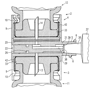
In the transfer device 1 illustrated ~~n Figures 1 and
2, the housing 2 :is formed by two housing halves 3 and
4 which are inserted into one another anc~ joined to one
another. The hous~~ng half 3 has a lateral connector_ 5
with external thread 6 onto which a closure cap 7 or
withdrawal syringe is screwed. In the area of the free
ends, the housing halves 3 and 4 have slits 8 which
extend in the longitudinal direction of the housing 2
and which between them form housing tabs 9 which, in
the area of their free ends, are provided with inwardly
directed locking projections 10. A glass 'vial 11, 12 is
inserted into the respective housing half 3, 4 and
secured by means of the locking projections. In the
initial state, the vial 11 holds a medical fluid, for
25' example, and the vial 12 holds a substance to be
dissolved. Before the vial 12 is inserted into the
transfer device l, a vacuum in particuzl~~r is created in
the interior thereof.
The structure of a first embodiment of the transfer
device is shown in Figure 3. The respective housing
part 3, 4 is made of plastic and forms a component part
with a respective piercing mandril 13, 14 which, in the
area of the center point of the respecti-cre base plate
15 of the respective housing part 3, 4, is connected to
said base plate .15. The length of the respective
piercing mandril 13, 14 is dimensioned so that it
reaches as far as t:he Pocking project~_or~s 10. The flow
channels 16, 17, re,~pectively, formed in the respective
CA 02459649 2004-03-04
piercing mandril 13, 14 continue gas portions 18, 19,
respectively, in the housing parts 3, 4. Where the two
housing parts 3 a-.~d 4 are inserted into one another and
securely joined to one another, a flat area is formed
into vahich a filter element 20 is fitted.
~.elative to the lengthwise orientation of the housing
2, hence the ler~gthmise orientation of the piercing
mandrill 13, 1~, ache housing part 3 is provided with a
passage 21 exter~c.ing perpendicular to i~hese. A slide
22, showr_ in detail in Figure 6, is inserted into this
passage from the aide directed away from the connector
5 . Thi.s slide has an essentz.all y rotationally
symmetrical design. Thus, the rotationally symmetrical
portion 24 of the slide 22 directed toward the rear
opening of the housing part 3 has a bead 25 which, in
this area, presses against the wall of i~he passage 21
and ensures that the slide 22 can be displaced only
when a sufficient axial force is introduced into this
passage. This bead 25 also seals of;E the slide 22
relative to the passage 21 of the housing part 3.
Adjoining the froni~ end of the rotat_Lonally symmetrical
portion 2~ there is a groove 26 running round the
circumference of the slide 22. Adjoining this groove
25' 26, in the direction toward the front, there is an
essentially rotationally symmetrical portion 27 whose
diameter corresponds to that of the rotationally
symmetrical portion 24, hence that alongside the bead
25. Finally, the portion 27 is adjoiraed, toward the
front, by an essentially rotationally symmetrical
portion 28 which has a smaller diameter than the
rotationally symmetrical portion 27. The portions 27
and 28 are provided with a V-shaped slit/ 29 which ends
at a distance from the groo~,re 26. The portion 27 is
flattened in the a~°ea of the V-shaped saLit 29, so that
two guide surfaces 30 are forr-,ed therE= o:r~ both sides of
the slit 29. Accordingly, as earl be seen from the view
in Figure 3 , the guide surface 32 o:E s. proj ection 31
extending into the ,passage 21 cooperates with the guide
CA 02459649 2004-03-04
_ 12 -
surface 30 of the slide 22. Consequently, the slide can
only be displaced in its longitudinal direction and
cannot be pivoted"
The transfer device described thus far functions in the
following way:
Figure 3 shows the transfer device 1 in the first
position of displacement of the slide 22. Here, the
groove 26 of the slide 22 is flush with the portions 18
in the housing part 3; the groove 26 i:~ thus in flow
connection with the frow channels 16 and 1'7 of the two
piercing mandrill 13 and l~. The connectc>r 5 is tightly
sealed by means of the cap '7. Starting from this
situation, the vial containing th.e fluid is first
inserted into the housing part 3. An elastic stopper 33
inserted into the opening of the vial 11 is pierced by
the piercing mandril 13. In the pasi.tion with the vial
11 fitted in the housing part 3, the locking
projections 10 of this housing part 3 engage behind the
bead 35 adjoining the neck 34 of the vial ll on the
stopper side. Before the vial 12 under vaeuum and
containing the medicament to be dissolved is connected
to the transfer device ~~, the latter is placed in the
25' position shown in :~"igures 3 and 4, that i.s to say with
the housing part ~3 arranged at the tap and with the
vial ll containing the fluid arranged at the top. The
other vial 12 is then correspondingly inserted into the
housing part 4, the piercing mandril ~.~4 piercing the
stopper 33 which seals this vial 12. With the vial 12
inserted fully into the housir_~g pax-t 4, the locking
projections 10 assigned to thus housing part engage
behind the bead 35 adjoining the neck 3<~ of this vial.
Since the piercing t-nandrils 13 and 14 protrude into the
interiors of the vials 11 and 12, the fluid is
transferred, by means of the zznderpressure in the vial
12, from the vial 11 and through flow channel 16,
groove 26 and flow ;::hannel 1'7 into the vial 12, and the
substance located in the latter is dissolved.
CA 02459649 2004-03-04
- 13
As is illustrate, in Figure 4, for lateral removal of
the dissolved substance from the transfer device l, the
closure cap 7 sea:Ling the slide area or~ the side remote
from the bead 25 is first unscrewed from the connector
5, as a result of ~~ahich the vacuum ~.s let down. The
transfer device 1, with the two via7_s 11. and 12 fitted
in it, is then turned 180° about the longitudinal axis
of the slide 22 tc_~ the position snowr~ .i.n Figure 5. A.s a
result, the vial 12 with the di ssolved substance in it
is located at the top, and the empty vi.a7_ 11 is located
underneath. Ta remove the dissolved substance, a
syringe cone 36 of: a syringe 37 (only part of which is
shown) is inserted sealingl~r into the conical opening
of the connector 5, as is illustrated in Figure 5. Upon
insertion of the ~>yringe cone 36 into rthe connector 5,
the front end 38 of the syringe cone 36 displaces the
slide 22, the syringe cone 36 making contact with a
tapering end 39 of the slide 22. In the position with
the syringe cone 36 inserted fully into the connector
5, the slide 22 assumes the second position of
displacement, show_;z in Figure 5, in which that end of
the slide 22 remote from the syringe 37 is still
located entirely Within the housing part 3, and the
25' flow channel 17 of. the piercing mandril 1~ is now in
flow connection aria portions 18 and 19 with the
V-shaped slit 29 in the slide 22, specifically in the
area of the V-shaped slit introduced into the portion
27. Thus, when the syringe 37 is being charged, the
vial I2 can be emptied via the flow connection from the
piercing mandril 1~ and the V-shaped slit 29 of the
slide 22.
In the embodiment according to Figures 3 throug:n 6P the
slide is rigid and :is made in particular of plastic.
A further embodiment of the transrer de~Tir~e 1 is shown
in Figures 7 through 9. This embodiment differs from
the first embodiment only in germs of trze slide 22 and
CA 02459649 2004-03-04
- 14 -
the canfiguratian of the housing part :3. Because of the
degree of correspondence, reference is therefore made
to the above description,
In the embodiment according to Figures 7 through 9, the
slide 22 is mad~a entirely of elastic material, in
particular of a thermoplastic elastomer (T~Ei or
rubber. The slide 22 is inserted v-ia the connector 5
into the housing part 3, and the lattef is closed in
the area of its end remote from the connector 5 a This
embodiment therefore does rlat have the opening 23 of
the first embodiment. In the embodiment according to
Figures 7 through 9, the portion 27, th.e portion 28 and
the V-shaped shit 29 of the slide 22 are of
corresponding design. The circumferents.a:L groove 26 is
considerably wider than the groove 26 of the first
embodiment, approximately as long as the portion 28.
Correspondingly, the portion 24 is de~;igned without a
bead 25 and is much shorter than the portion 24 of the
first embodiment. The portion 24 additionally has a
flattened area 32 on its top, which flattened area 32
cooperates with a guide surface 31 of the housing part
3 arranged in this area . The detailed structure of the
slide 22 in this er:7badiment is illustrated in Figure 9.
25'
Figure 7 shows this embodiment in the first position of
displacement of the slide, specifically in the state in
which the vial 12 containing the dissolved substance
has already been pi.vated to t.'ne top. The sl~.de 22 bears
on the housing wail 40 remote from the connector 5. The
flow connection of the flow channels 1~ and 17 of the
piercing mandrils 13 and z4 is obtained via the groo-Ve
26. As is illustrated in Figure 8 and has already been
explained in detai:_, i:~n order_ to remove the dissolved
substance the syringe cone 36 is ,ynserted into the
connector 5, in which process its front end makes
contact with the slide 22, and, in the ar'a of reduced
cross section 41 where the groove 26 is defined,
deforms the slide 22 as a result of the elastic
CA 02459649 2004-03-04
- 15 -
property of said slide 22e The aefor_ma~tion in this area
of the slide 22 and, consequently, the fact tha~;~ the
area of the slide 22 facing the syringe cone 36 is
displaced in the direction of the hau~~,ing wall 40 mean
that, as is illustrated in Figure 8, the flow channel
17 of the piercing mandril 14 comes into flow
connection with the ~l-shaped slit 29..
In this conte~.t, an important dart is played by the
slide 22 preferably made of TPE. Its elastic property
simplifies the sealing of the slide 22 relative to the
housing part 3, so that, in both positions of
displacement of t~-~.e slide 22, distinct streams of fluid
can be routed t:_:~rough the transfer device without
leakages. The slic'~e 22 made of thermoplastic elastomer
has a spring effect, so that the system automatica:Lly
closes wher~ the syringe 37 is withdrawn from the
connector 5. In tris case, the slide 22 is immediately
moved to its first position of_ displacement.
In the first embodiment according to Figures 3 through
6, in which the slide 22 is rigid, the bead 25 not only
defines the respective starting positior~ of the slide,
it in particular peals off the passage 21 at the end
~ remote from the co:n.nector 5 . This is irriportant for the
function of the device. If this seal were not tc
function, the vacuum in the vial 12 containing the
substance to be dissolved would be reduced and a
transfer possible. in the embodiment according to
Figures 7 through ~, with the elastic slide 22 and with
the differently designed housing par. 3, the elastic
slide 22 provides direct sealing because of its
material properties. In addition, the elastic slide 22
can be introduced from the removal side. In this way,
the passage 21 in the area of the end of the housing 2
remote from the connector 5 can be omitted, as a result
of which the sealir~g problem is reduced.
CA 02459649 2004-03-04
_ 1~
In both embodiments, the closure of the flow channel 16
ensures that air cannot be drawn it from the vial 11.
This is important for the removal of the dissolved
substance or dis~~olved medicament. wring removal, an
underpressure is generated with the syringe 37, as a
result of which the dissolved substance flows into the
syringe. If the vial 11 were open,. they underpressure
generated in the syringe 37 would be reduced and
filling of the syringe 37 would thus be made
considerably difficult.
Reference number 42 indicates a cap-like film seal
which surrounds the bead 35 of the .respective vial 11,
12 and also the stopper 33 inserted i.m the latter, by
which means the stopper is held securely in the vial.
CA 02459649 2004-03-04
_ 1"?
i
Fist of reference numbers
1 transfer device
2 housing
3 housing part
4 housing :part
5 connecto:c
6 thread
7 closure cap
8 slit
9 housing ~~ab
10 locking proj ection
11. glaSS v1<~~.
12 glass vial
13 piercing mandril
14 piercing mandril
15 base plate
16 flow channel
17 flow channel
18 portion
i9 portion
20 filter element
21 passage
25' 22 slide
23 opening
24 portion
bead
26 groove
27 portion
28 portion
29 slit
30 guide surface
31 proj ectioxz
32 guide surface
33 stopper
34 neck of vial
35 bead
36 syringe cone
CA 02459649 2004-03-04
37 syringe
38 end
39 end
40 housing gall
41 crass section
42 film seal