Note: Descriptions are shown in the official language in which they were submitted.
CA 02459710 2004-03-04
WO 03/020368 PCT/US02/28037
MEDICAL LEAD CONNECTOR
FIELD
The invention relates to implantable medical devices and, more particularly,
to
electrical leads for use with such devices.
BACKGROUND
Implantable medical devices (IMDs), such as implantable
1o cardioverter/defibrillators (ICDs), pacemaker/cardioverter/defibrillators
(PCDs), and
pacemakers can detect and administer therapy for a variety of conditions.
These
conditions include ventricular fibrillation (VF), atrial fibrillation (AF),
tachycardia, and
bradycardia.
Various types of transvenous pacing and cardioversionldefibrillation leads
have
been developed for use with >ZVVIDs. These leads are typically flexible to
facilitate insertion
and placement into the body of the patient, and are usually constructed with
an outer
polymeric sheath encasing a coiled wire conductor. The coiled wire conductor
is typically
attached at a distal end to a shank portion of a tip electrode. A proximal end
of the coiled
wire conductor is coupled to a lead connector end assembly.
2o Different manufacturers often produce implantable cardiac leads with lead
connector end assemblies that match connector block terminals of IMDs from a
common
manufacturer. More recently, a number of manufacturers have adopted a single
dimensional pacemaker connector standard known as the low-profile comiectox
"IS-1"
standard (ISO 584.1-3:1992(E)) for bipolar in-line and unipolar lead connector
end
assemblies. Compatibility with the IS-1 standard ensures that leads made by
one
manufacturer can be interchangeably used in connection with an IMD made by a
different
manufacturer.
In some conventional lead systems, a lead body is implanted through a guide
catheter, which is then pulled off the lead body after implantation.
Typically, the electrical
so connector attached to the end of the lead body has a larger diameter than
the lead body.
As a result, in such lead systems, pulling the guide catheter off the lead
body can be
difficult. Moreover, some connectors do not implement the low- profile design
of the IS-1
CA 02459710 2004-03-04
WO 03/020368 PCT/US02/28037
2
standard, making post-implantation removal of the guide catheter even more
difficult. In
lead systems implementing such high-profile connectors, the guide catheter
used must
have a larger diameter, making lead placement in some places, such as the
coronary sinus,
difficult.
SUMMARY
The invention is generally directed to electrical connectors that can be
attached to
an implanted lead body. More particularly, various embodiments of the
invention provide
electrical connectors that have a compressible portion that expands to accept
an inserted
lead arid then contracts around the lead to provide both an electrical and a
spring-like
mechanical connection to the lead. In one embodiment, the connector has a
fluted pin that
collapses around the lead body when a set screw of the connector port is
tightened. In
another embodiment, a middle segment of a pin has indentations or slots that
collapse
~ 5 around an inserted lead body. Both embodiments are compatible with the IS-
1 standard
for pacemaker leads.
The invention provides a number of advantages. For example, the electrical
connector can be attached to the lead body after the lead body is implanted in
the body of
a patient. In lead systems in which the lead body is implanted using a guide
catheter,
2o attaching the connector to the lead body after implantation allows removal
of the guide
catheter before the connector is attached. Because the guide catheter does not
have to
overcome mechanical resistance imparted by the larger diameter of the
connector
compared to the lead body, removal of the guide catheter is facilitated.
One embodiment of the invention is directed to an electrical connector that
25 includes a first portion that defines a channel for receipt of a medical
lead. An electrically
conductive collapsible portion is operatively coupled to the first portion and
is arranged to
collapse around a portion of the medical lead upon receipt of the medical lead
in the
channel.
In a specific embodiment, the collapsible portion comprises a proximal portion
of
so the electrical connector that has longitudinal slots that cause the
proximal portion to
collapse around the portion of the medical lead when a set screw of a
comiector port is
CA 02459710 2004-03-04
WO 03/020368 PCT/US02/28037
3
tightened. When tightened, the set screw applies a force to the proximal
portion that
causes the proximal portion of the connector to collapse around the lead.
In another specific embodiment, the collapsible portion comprises a middle
portion
of the electrical connector that is disposed between the first portion of the
connector and a
proximal portion of the electrical connector. The middle portion has a slot
arranged to
cause the middle portion to collapse around the portion of the medical lead.
These
connectors may be implemented as part of a lead system.
Another embodiment of the invention is directed to a method of attaching an
electrical connector to a medical lead. The medical lead is implanted in the
body of the
patient. A portion of the medical lead is threaded through a distal portion of
an electrical
connector. Next, an electrically conductive collapsible portion of the
electrical connector
is caused to collapse around the portion of the medical lead, for example, by
tightening a
set screw of a connector port to apply a force to the collapsible portion.
The above summary of the invention is not intended to describe every
embodiment
~ 5 of the invention. The details of one or more embodiments of the invention
are set forth in
the accompanying drawings and the description below. Other features, objects,
and
advantages of the invention will be apparent from the description and
drawings, and from
the claims.
2o BRIEF DESCRIPTION OF DRAWINGS
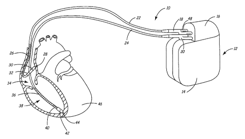
FIG. 1 is a diagram illustrating an implantable medical device system.
FIG. 2 is a sectional view of an electrical connector for use with the
implantable
medical device system of FIG. 1, according to an embodiment of the present
invention.
FIG. 3 is a sectional view of another electrical connector for use with the
25 implantable medical device system of FIG. 1, according to another
embodiment of the
present invention.
FIG. 4 is a flow diagram depicting an example process for attaching an
electrical
connector to a medical lead according to the invention.
3o DETAILED DESCRIPTION
FIG. 1 illustrates an implantable medical device (IMD) system 10 in which the
present invention may be practiced. IMD system 10 is shown in association with
a human
CA 02459710 2004-03-04
WO 03/020368 PCT/US02/28037
4
heart 46. As shown in FIG. 1, IMD system 10 includes a
pacemaker/cardioverter/defibrillator (PCD) 12 having a housing 14 and a
connector block
16. IMD system 10 may be implemented using any of a number of medical devices,
including, but not limited to, a pacemaker, PCD 12 or an implantable cardiac
defibrillator
(ICD). Other techniques or therapies responsive to EGM signals, such as
therapies that
administer drugs in response to atrial arrhythmia, also may implement various
embodiments of the invention.
Optionally, insulation of the outward facing portion of housing 14 of PCD 12
may
be provided using a plastic coating, such as parylene or silicone rubber, as
is employed in
1 o some unipolar cardiac pacemakers. However, the outward facing portion may
instead be
left uninsulated, or some other division between insulated and uninsulated
portions may be
employed. The uninsulated portion of the housing 14 optionally serves as a
subcutaneous
defibrillation electrode, used to defibrillate either the atria or ventricles.
IMD system 10 comprises a ventricular lead, which includes an elongated
insulated lead body 24, carrying three concentric coiled conductors separated
from one
another by tubular insulative sheaths. The distal end of the ventricular lead
is deployed in
right ventricle 38. Located adjacent the distal end of the ventricular lead
are a ring
electrode 40, an extendable helix electrode 44, mounted retractably within an
insulative
electrode head 42, and an elongated (approximately 5 cm) defibrillation coil
electrode 36.
2o Deftbrillation electrode 36 may be fabricated from many materials, such as
platinum or
platinum alloy. Each of the electrodes is coupled to one of the coiled
conductors within
lead body 24.
Electrodes 40 and 44 are employed for cardiac pacing and for sensing
ventricular
depolarizations. Accordingly, electrades 40 and 44 serve as sensors for a V-
EGM. At the
proximal end of the ventricular lead is a bifurcated connector 20 that carries
three
electrical connectors, each coupled to one of the coiled conductors.
The atrial/superior vena cava (SVC) lead includes an elongated insulated lead
body
22, carrying three concentric coiled conductors, separated from one another by
tubular
insulative sheaths, corresponding to the structure of the ventricular lead.
The distal end of
3o the atrial/SVC lead is deployed in right atrium 34. Located adjacent the
distal end of the
atrial/SVC lead are a ring electrode 32 and an extendable helix electrode 28,
mounted
retractably within an insulative electrode head 30. Each of the electrodes is
coupled to one
CA 02459710 2004-03-04
WO 03/020368 PCT/US02/28037
of the coiled conductors within lead body 22. Electrodes 28 and 32 are
employed for atrial
pacing and for sensing atrial depolarizations. Accordingly, electrodes 28 and
32 serve as
sensors for an A-EGM.
An elongated coil electrode 26 is provided proximal to electrode 32 and
coupled to
the third conductor within lead body 22. Electrode 26 is preferably at least
10 cm long
and is configured to extend from the SVC toward the tricuspid valve. At the
proximal end
of the lead is a bifurcated connector 18 that carries three electrical
connectors, each
coupled to one of the coiled conductors.
Implantable PCD 12 is shown in combination with the leads, with lead connector
1o assemblies 18 and 20 inserted into low-profile IS-1 type connector ports 48
on connector
block 16. Although an IS-1 type connector may employ the current invention, it
will be
understood that the invention may also be utilized with any other type of
standard or non-
standard connector. For example, the invention is particularly useful when
larger-profile
connectors are utilized, since these connectors make guide catheter removal
more difficult
following lead placement during an implant procedure.
According to various embodiments of the invention, one or more of lead
connector
assemblies 18 and 20 may have a compressible portion that expands to accept an
inserted
lead and then contracts around the lead to provide both an electrical and a
spring-like
mechanical connection to the lead. In one embodiment, the connector has a
fluted pin that
2o collapses around the lead body when a set screw of the connector port is
tightened. Tn
another embodiment, a middle segment of a pin has indentations or slots that
collapse
around an inserted lead body. Both embodiments are compatible with the IS-1
standard
fox pacemaker leads.
The invention provides a number of advantages. For example, the electrical
connector can be attached to the lead body after the lead body is implanted in
the body of
the patient. In Iead systems in which the lead body is implanted using a guide
catheter,
attaching the connector to the lead body after implantation allows removal of
the guide
catheter before the connector is attached. Because the guide catheter does not
have to
overcome mechanical resistance imparted by the larger diameter of the
connector
ao compared to the Lead body, removal of the guide catheter is facilitated.
FIG. 2 is a side view of an example electrical connector assembly 50 that may
be
attached to the end of lead body 22 or 24 of FIG. 1. Electrical connector
assembly 50 can
CA 02459710 2004-03-04
WO 03/020368 PCT/US02/28037
6
be used with a variety of leads, including leads compliant with the IS-1
standard for
pacemaker leads. As shown in FIG. 2, connector assembly 50 includes sealing
rings 52
and an electrically conductive connector pin 54 having a number of
longitudinal slots 56
cut along the perimeter of the proximal end of pin 54 so as to form a number
of flanges 58.
Sealing rings 52 protect connector pin 54 and PCD 12 against ingress of
external
contaminants.
A lead body includes an elongated lead conductor 60 formed of coiled wire
covered with an insulator 62, which may be fabricated of silicone rubber,
polyurethane, or
other suitable plastic. The lead body may be implanted within a vein of the
patient with an
electrode at its distal end affixed to tissue in the right ventricle of the
patient. A guide
catheter, guide wire, and/or any other lead delivery device may be used to
facilitate
placement of the lead body. These delivery devices are removed after the lead
body is
implanted.
After the guide catheter is removed, connector assembly 50 is attached at the
proximal end of the lead body by threading lead conductor 60 through connector
assembly
50. The portion of lead conductor 60 that protrudes from the tip of connector
pin 54 may
then be cut off to the desired length. As an alternative, pin 54 may be
manufactured with
longitudinal slots 56 extending across less than the entire length of the
proximal end of pin
54. With this construction, the tip of pin 54 is closed such that lead
conductor 60 does not
2o protrude from pin 54.
After lead conductor 60 is threaded through connector body 50, pin 54 is
inserted
into IS-1 connector port 48 on the pacemaker. The IS-1 connector port has a
set screw
that, when tightened, contacts and applies a force to one or more of the
flanges 58, causing
it to deflect toward lead conductor 60. As a result, pin 54 collapses around
and grips lead
conductor 60. Flange 58 crushes and breaches insulator 62 when flange 58 is
deflected by
tightening the set screw, making contact with lead conductor 60. By causing
pin 54 to
grip lead conductor 60 and to breach insulator 62, the set screw establishes
both a
mechanical connection and an electrical connection between the connector port,
pin 54,
and lead conductor 60.
3o Advantageously, attaching connector assembly 50 to the lead body after
implanting
the lead body facilitates removal of the guide catheter, as the guide catheter
does riot need
CA 02459710 2004-03-04
WO 03/020368 PCT/US02/28037
7
to overcome the mechanical resistance that would otherwise be presented by the
larger
diameter of connector assembly 50 compared to lead conductor 60.
According to another embodiment of the present invention illustrated in
FIG. 3, an electrically conductive sleeve 70 is crimped on a lead body 72 to
make
electrical contact with lead body 72 and is secured to lead body 72 with
adhesive. While
not required, optional apertures 74 in sleeve 70 may provide visual
confirmation that
adhesive has been used to secure lead body 72. Lead body 72 with crimped
sleeve 70 is
then pulled through an electrically conductive connector body 76 having a
deflectable
section 78. Deflectable section 78 may be formed, for example, by forming
slots on
1 o connector body 76 using electron displacement machining (ED1VI) or another
suitable
technique. The slots are deflected to provide an interference fit with sleeve
70. The slots
impart some flexibility to deflectable section 78. In a nondeflected state,
deflectable
section 78 has an inner diameter smaller than the outer diameter of sleeve 70.
As a result,
when sleeve 70 is pulled through connector body 76, deflectable section 78
expands to
accept sleeve 70. Deflectable section 78 thereby exerts a spring force on
sleeve 70 to
secure sleeve 70 in place. The spring force establishes mechanical and
electrical contact
between connector body 76, sleeve 70, and lead body 72. In addition, connector
body 76
may include a stop 80 to prevent sleeve 70 from being pulled beyond stop 80.
Connector body 76 rnay be molded inside a tube (not shown) and secured with
2o silicone rubber. To isolate the portion of sleeve 70 exposed by the slots
formed on
deflectable section 78, connector body 76 includes a number of sealing rings
82. Sealing
rings 82 form a seal with the tube to prevent ingress of the silicone rubber
into deflectable
section 78, thereby preventing contact between the silicone rubber with sleeve
70.
FIG. 4 is a flow diagram depicting an example process for attaching an
electrical
comzector to a medical lead, according to the current invention. First, the
medical Iead is
implanted in the body of the patient (90). Implanting the lead typically
involves attaching
a distal end of the lead to cardiac tissue and using a guide catheter,
introducer sheath, or
other delivery device to facilitate proper placement of the lead. The delivery
device is
then withdrawn from the body of the patient (92) before attaching the
connector. After the
lead is placed, a proximal portion of the lead is threaded through a distal
portion of an
electrical connector (94), such as the connector shown in FIG. 2 or the
connector shown in
FIGS. 3. Advantageously, attaching the connector after withdrawing the
delivery device
CA 02459710 2004-03-04
WO 03/020368 PCT/US02/28037
8
from the body facilitates removal of the delivery device. In addition, while
not required, a
portion of the lead extending proximal to the connector is optionally cut off
(96) after the
connector is positioned. Accordingly, the lead length can be tailored to the
physiology of
the patient.
To establish mechanical and electrical contact between the lead and the
connector,
an electrically conductive collapsible portion of the electrical connector is
caused to
collapse around the portion of the medical lead (98). As described above in
connection
with FIG. 2, this may be achieved by tightening a set screw, thereby applying
a force to
the connector that causes the connector to tighten around the lead.
Alternatively, if the
1 o comzector shown in FIGS. 3 is used, the connector may be collapsed around
the lead by
spring force of indentations 74, and thereby creating a spring force that
establishes
mechanical and electrical contact.
As described above, the invention may provide certain advantages in the
implantation process. For example, the connectors shown in FIGS. 2-3 may be
attached to
a lead body alter the lead body is implanted in the patient. As a result, a
guide catheter
used to promote proper placement of the lead body can be easily removed from
the lead
body without having to overcome mechanical resistance presented by a connector
having a
larger diameter than the lead body. Various embodiments of the invention have
been
described. These embodiments are illustrative of the practice of the
invention. These and
other embodiments are within the scope of the following claims.