Note: Descriptions are shown in the official language in which they were submitted.
CA 02459952 2004-03-08
WO 03/024504 PCT/US02/28053
PLUNGER FOR PATIENT INFUSION DEVICE
Cross-Reference to Related Applications
(O1) The present application is related to U.S. patent application serial
number 09/943,992, filed on August 3I, 2001, which is assigned to the assignee
of the
present application and incorporated herein by reference.
Field of the Tnvention
(02) The present invention relates generally to medical devices, systems and
methods, and more particularly to small, low cost, portable infusion devices
and
methods that are useable to achieve precise, sophisticated, and programmable
flow
patterns for the delivery of therapeutic liquids to a mammalian patient.
Background of the Invention
(03) Today, there are numerous diseases and other physical ailments that are
treated by various medicines including pharmaceuticals, nutritional formulas,
biologically derived or active agents, hormonal and gene based material and
other
substances in both solid or liquid form. In the delivery of these medicines,
it is often
desirable to bypass the digestive system of a mammalian patient to avoid
degradation
of the active ingredients caused by the catalytic enzymes in the digestive
tract and liver.
Delivery of a medicine other than by way of the intestines is known as
paxenteral
delivery. Parenteral delivery of various drugs in liquid form is often desired
to enhance
the effect of the substance being delivered, insuring that the unaltered
medicine reaches
its intended site at a significant concentration. Also, undesired side effects
associated
with other routes of delivery, such as systemic toxicity, can potentially be
avoided.
(04) Often, a medicine may only be available in a liquid form, or the liquid
version may have desirable characteristics that cannot be achieved with solid
or pill
form. Delivery of liquid medicines may best be accomplished by infusing
directly into
the cardiovascular system via veins or arteries, into the subcutaneous tissue
or directly
into organs, tumors, cavities, bones or other site specific locations within
the body.
CA 02459952 2004-03-08
WO 03/024504 PCT/US02/28053
(OS) Parenteral delivery of liquid medicines into the body is often
accomplished by administering bolus injections using a needle and reservoir,
or
continuously by gravity driven dispensers or transdermal patch technologies.
Bolus
inj ections often imperfectly match the clinical needs of the patient, and
usually require
larger individual doses than are desired at the specific time they are given.
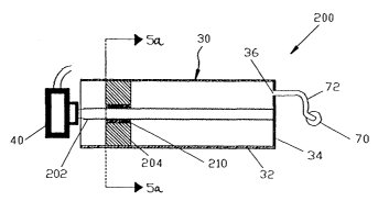
Continuous
delivery of medicine through gravity feed systems compromise the patient's
mobility
and lifestyle, and limit the therapy to simplistic flow rates and profiles.
Transdermal
patches have special requirements of the medicine being delivered,
particularly as it
relates to the molecularvstructure, and similar to gravity feed systems, the
control of the
drug administration is severely limited.
(06) Ambulatory infusion pumps have been developed for delivering liquid
medicaments to a patient. These infusion devices have the ability to offer
sophisticated
fluid delivery profiles accomplishing bolus requirements, continuous infusion
and
variable flow rate delivery. These infusion capabilities usually result in
better efficacy
of the drug and therapy and less toxicity to the patient's system. An example
of a use
of an ambulatory infusion pump is for the delivery of insulin for the
treatment of
diabetes mellitus. These pumps can deliver insulin on a continuous basal basis
as well
as a bolus basis as is disclosed in U.S. Patent 4,498,843 to Schneider et al.
(07) The ambulatory pumps often work with a reservoir to contain the liquid
medicine, such as a cartridge or reservoir, and use electro-mechanical pumping
or
metering technology to deliver the medication to the patient via tubing from
the
infusion device to a needle that is inserted transcutaneously, or through the
skin of the
patient. The devices allow control and programming via electromechanical
buttons or
switches located on the housing of the device, and accessed by the patient or
clinician.
The devices include visual feedback via text or graphic screens, such as
liquid crystal
displays known as LCD's, and may include alert or warning lights and audio or
vibration signals and alarms. The device can be worn in a harness or pocket or
strapped to the body of the patient.
2
CA 02459952 2004-03-08
WO 03/024504 PCT/US02/28053
(08) Currently available ambulatory infusion devices are expensive, difficult
to program and prepare for infusion, and tend to be bulky, heavy and very
fragile.
Filling these devices can be difficult and require the patient to carry both
the intended
medication as well as filling accessories. The devices require specialized
care,
maintenance, and cleaning to assure proper functionality and safety for their
intended
long term use. Due to the high cost of existing devices, healthcare providers
limit the
patient populations approved to use the devices and therapies for which the
devices can
be used.
(09) Clearly, therefore, there was a need for a programmable and adjustable
infusion system that is precise and reliable and can offer clinicians and
patients a small,
low cost, light weight, simple to use alternative for parenteral delivery of
liquid
medicines.
(10) In response, the applicant of the present application provided a small,
low cost, light weight, easy to use device for delivering liquid medicines to
a patient.
The device, which is described in detail in co-pending U.S. application serial
No.
09/943,992, filed on August 31, 2001, includes an exit port, a dispenser for
causing
fluid from a reservoir to flow to the exit port, a local processor programmed
to cause a
flow of fluid to the exit port based on flow instructions from a separate,
remote control
device, and a wireless receiver connected to the local processor for receiving
the flow
instructions. To reduce the size, complexity and costs of the device, the
device is
provided with a housing that is free of user input components, such as a
keypad, for
providing flow instructions to the local processor.
(11) What is still desired are new and improved dispensers and reservoirs for
use with devices for delivering fluid to a patient. Preferably, the dispensers
and
reservoirs will be simple in design, and inexpensive and easy to manufacture,
in order
to fiuther reduce the size, complexity and costs of fluid delivery devices,
such that the
devices lend themselves to being small and disposable in nature.
CA 02459952 2004-03-08
WO 03/024504 PCT/US02/28053
Summary of the Invention
(12) In response, the present invention provides a device for delivering fluid
to a patient, including an exit port assembly adapted to connect to a
transcutaneous
patient access tool, a reservoir including a side wall extending towards an
outlet
connected to the exit port assembly, at least one threaded lead screw received
in the
reservoir and extending towards the outlet of the reservoir generally parallel
with the
side wall, and a plunger thxeadedly received on the lead screw such that
rotating one of
the lead screw and the plunger moves the plunger within the reservoir. The
device also
includes a dispenser operatively coupled to one of the lead screw and the
plunger for
rotating one of the lead screw and the plunger. The lead screw driven plunger
reduces
the size, complexity and costs of the device so that the device lends itself
to being small
and disposable in nature.
(13) Another device according to the present invention includes an exit port
assembly, a reservoir having a side wall extending towards an outlet connected
to the
exit port assembly, and a plunger slidingly received within the side wall of
the
reservoir. The device also includes a shaft extending from the plunger and a
dispenser
operatively coupled to the shaft for causing movement of the shaft along an
axis of the
shaft. The shaft is relatively incompressible along the axis of the shaft and
is bendable
traverse to the axis, such that the shaft can be bent yet still used to move
the plunger,
such that the length of the device can be reduced.
(14) The present invention provides an additional device for delivering fluid
to a patient, including an exit port assembly, a reservoir including an outlet
connected
to the exit port assembly, a plunger movably received in the reservoir for
forcing fluid
through the outlet upon moving within the reservoir, and a dispenser for
moving the
plunger within the reservoir. The device also includes a local processor
connected to
the dispenser and programmed to cause a flow of fluid to the exit port
assembly based
on flow instructions, a wireless receiver connected to the local processor for
receiving
flow instructions from a separate, remote control device and delivering the
flow
instructions to the local processor, and a housing containing the exit port
assembly, the
4
CA 02459952 2004-03-08
WO 03/024504 PCT/US02/28053
reservoir, the dispenser, the local processor, and the wireless receiver.
Preferably, the
housing is free of user input components for providing flow instructions to
the local
processor, in order to reduce the size, complexity and costs of the device so
that the
device Iends itself to being small and disposable in nature.
(15) A further device according to the present invention includes an exit port
assembly, a reservoir including an outlet connected to the exit port assembly,
a plunger
movably received in the reservoir for forcing fluid through the outlet to the
exit port
assembly upon moving within the reservoir, and a dispenser for moving the
plunger
within the reservoir. A local processor is connected to the dispenser and
programmed
to cause a flow of fluid to the exit port assembly based upon flow
instructions, and
further programmed to provide flow information, and a wireless transmitter is
connected to the local processor for transmitting the flow information from
the local
processor to a separate, remote control device. The device also includes a
housing
containing the exit port assembly, the reservoir, the dispenser, the local
processor, and
the wireless transmitter, wherein the housing is free of user output
components for
providing the flow information from the local processor to a user.
(16) These aspects of the invention together with additional features and
advantages thereof may best be understood by reference to the following
detailed
descriptions and examples taken in connection with the accompanying
illustrated
drawings.
Brief Description of the Drawings
(17) Fig. I is a perspective view of a first exemplary embodiment of a fluid
delivery device in accordance with this invention shown secured on a patient,
and a
remote control device for use with the fluid delivery device (the remote
control device
being enlarged with respect to the patient and the fluid delivery device for
purposes of
illustration);
(18) Fig. 2 is a sectional side view of the fluid delivery device of Fig. 1;
CA 02459952 2004-03-08
WO 03/024504 PCT/US02/28053
(19) Fig. 3 is a sectional side view of a reservoir, a plunger and a lead
screw
of the fluid delivery device of Fig. l;
(20) Fig. 4 is an enlarged sectional view of a plunger and lead screw of the
fluid delivery device of Fig. 1;
(21) Fig. 5a is a sectional view of the reservoir, the plunger and the lead
screw of the fluid delivery device of Fig. 1 taken along line 5--5 of Fig. 3;
(2,2) Fig. 5b is a sectional view of another exemplary embodiment of a
reservoir, a plunger and a lead screw constructed in accordance with the
present
invention for use with the fluid delivery device of Fig. l;
(23) Fig. 6 is an exploded sectional side view of another exemplary
embodiment of a reservoir, a plunger and a lead screw constructed in
accordance with
the present invention for use with the fluid delivery device of Fig. 1;
(24) Fig. 7 is a sectional side view of the reservoir, the plunger and the
lead
screw of Fig. 4;
(25) Fig. ~ is a sectional side view of an additional exemplary embodiment of
a reservoir, a plunger and a lead screw constructed in accordance with the
present
invention for use with the fluid delivery device of Fig. 1;
(26) Fig. 9 is a sectional side view of a further exemplary embodiment of a
reservoir, a plunger and a lead screw constructed in accordance with the
present
invention for use with the fluid delivery device of Fig. 1;
(27) Fig. 10 is a sectional side view of still another exemplary embodiment of
a reservoir, a plunger and a lead screw constructed in accordance with the
present
invention for use with the fluid delivery device of Fig. 1;
6
CA 02459952 2004-03-08
WO 03/024504 PCT/US02/28053
(28) Fig. 11 is a sectional side view of an additional exemplary embodiment
of a reservoir, a plunger and a lead screw constructed in accordance with the
present
invention for use with the fluid delivery device ofFig. I;
(29) Fig. 12 is a sectional side view of a further exemplary embodiment of a
reservoir, a plunger and a lead screw constructed in accordance with the
present
invention for use with the fluid delivery device of Fig. 1;
(30) Fig. 13a is a sectional side view of yet another exemplary embodiment
of a reservoir, a plunger and a lead screw constructed in accordance with the
present
invention for use with the fluid delivery device of Fig. 1;
(31) Fig. 13b is a sectional view of the reservoir, the plunger and the lead
screw of Fig. 13a, shown with a needle being inserted into a port of the
reservoir;
(32) Fig. I4 is an end elevation view of the plunger of Figs. I3a and I3b;
(33) Fig. 15 is a sectional view of the lead screw and a thread cover of Figs.
13a and 13b;
(34) Fig. 16 is a sectional view of the lead screw and the thread cover
coaxially received within the plunger of Figs. 13a and I3b;
(35) Fig. 17a is a side elevation view of the lead screw and the thread cover
of Figs. 13a and 13b, wherein threads of the lead screw are covered within the
thread
cover;
(36) Fig. 17b is a side elevation view of the lead screw and the thread cover
of Figs. 13a and 13b, wherein the Iead screw has been rotated within the
thread cover to
reveal the threads of the lead screw;
(37) Fig. 18a is a sectional side view of another exemplary embodiment of a
reservoir, a plunger and a Iead screw constructed in accordance with the
present
invention for use with the fluid delivery device of Fig. 1;
7
CA 02459952 2004-03-08
WO 03/024504 PCT/US02/28053
(38) Fig. 18b is a sectional view of the reservoir, the plunger and the lead
screw of Fig. 18b, shown with a needle being inserted into a port of the
reservoir;
(39) Fig. 19 is a sectional side view of an additional exemplary embodiment
of a reservoir, a plunger and a lead screw constructed in accordance with the
present
invention for use with the fluid delivery device of Fig. l; and
(40) Fig. 20 is a sectional side view of a further exemplary embodiment of a
reservoir constructed in accordance with the present invention for use with
the fluid
delivery device of Fig. 1.
(41) Like reference characters designate identical or corresponding
components and units throughout the several views.
Detailed Describtion of the Preferred Embodiments
(42) Referring first to Figs. 1 and 2, there is illustrated a fluid delivery
device
constructed in accordance with the present invention. The types of liquids
that can
be delivered by the fluid delivery device of the present invention include,
but are not
limited to, insulin, antibiotics, nutritional fluids, total parenteral
nutrition or TPN,
analgesics, morphine, hormones or hormonal drugs, gene therapy drugs,
anticoagulants,
analgesics, cardiovascular medications, AZT or chemotherapeutics. The types of
medical conditions that the fluid delivery device of the present invention
might be used
to treat include, but are not limited to, diabetes, cardiovascular disease,
pain, chronic
pain, cancer, AIDS, neurological diseases, Alzheimer's Disease, ALS,
Hepatitis,
Parkinson's Disease or spasticity.
(43) Referring to Fig. 2, the device 10 generally includes an exit port
assembly 70 adapted to connect to a transcutaneous patient access tool such as
a needle,
a dispenser 40 for causing fluid from a reservoir 30 to flow to the exit port
assembly,
and a processor or electronic microcontroller (hereinafter referred to as the
"local"
processor) 50 comlected to the dispenser.
8
CA 02459952 2004-03-08
WO 03/024504 PCT/US02/28053
(44) The local processor SO is prograrmned to cause a flow of fluid to the
exit
port assembly 70 based on flow instructions from a separate, remote control
device
100, an example of which is shown in Fig. 1. Referring also to Fig. 2, the
fluid delivery
device I O further includes a wireless receiver 60 connected to the local
processor 50 for
receiving the flow instructions from the separate, remote control device 100
and
delivering the flow instructions to the local processor. The device 10 also
includes a
housing 20 containing the exit port assembly 70, the reservoir 30, the
dispenser 40, the
local processor 50, and the wireless receiver 60.
(45) As shown, the housing 20 is free of user input components for providing
flow instructions to the local processor 50, such as electromechanical
switches or
buttons on an outer surface 21 of the housing, or interfaces otherwise
accessible to a
user to adjust the programmed flow rate through the local processor 50. The
lack of
user input components allows the size, complexity and costs of the device 10
to be
substantially reduced so that the device 10 lends itself to being small and
disposable in
nature.
(46) In order to program, adjust the programming of, or otherwise
communicate user inputs to the local processor 50, the fluid delivery device
10 includes
the wireless communication element, or receiver 60 for receiving the user
inputs from
the separate, remote control device 100 of Fig. 1. Signals can be sent via a
communication element (not shown) of the remote control device 100, which can
include or be connected to an antenna 130, shown in Fig. 2 as being external
to the
device 100.
(47) The remote control device 100 has user input components, including an
array of electromechanical switches, such as the membrane keypad 120 shown.
The
control device 100 also includes user output components, including a visual
display,
such as a liquid crystal display (LCD) 110. Alternatively, the control device
can be
provided with a touch screen for both user input and output. Although not
shown in
Fig. 1, the remote control device 100 has its own processor (hereinafter
referred to as
the "remote" processor) connected to the membrane keypad 120 and the LCD 110.
The
9
CA 02459952 2004-03-08
WO 03/024504 PCT/US02/28053
remote processor receives the user inputs from the membrane keypad 120 and
provides
"flow" instructions for transmission to the fluid delivery device 10, and
provides
information to the LCD 110. Since the remote control device 100 also includes
a visual
display 110, the fluid delivery device 10 can be void of an information
screen, further
reducing the size, complexity and costs of the device 10.
(48) The communication element 60 of the device 10 preferably receives
electronic communication from the remote control device 100 using radio
frequency or
other wireless communication standards and protocols. In a preferred
embodiment, the
communication element 60 is a two-way communication element, including a
receiver
and a transmitter, for allowing the fluid delivery device 10 to send
information back to
the remote control device 100. In such an embodiment, the remote control
device 100
also includes an integral communication element 60 comprising a receiver and a
transmittex, for allowing the remote control device 100 to receive the
information sent
by the fluid delivery device 10.
(49) The local processor 50 of the device 10 contains all the computer
programs and electronic circuitry needed to allow a user to program the
desired flow
patterns and adjust the program as necessary. Such circuitry can include one
or more
microprocessors, digital and analog integrated circuits, resistors,
capacitors, transistors
and other semiconductors and other electronic components known to those
skilled in
the art. The local processor 50 also includes programming, electronic
circuitry and
memory to properly activate the dispenser 40 at the needed time intervals.
(50) In the exemplary embodiment of Fig. 2, the device 10 includes a power
supply 80, such as a battery or capacitor, for supplying power to the local
processor 50.
The power supply 80 is preferably integrated into the fluid delivery device
10, but can
be provided as replaceable, e.g., a replaceable battery.
(51) Although not shown, the device can include sensors or transducers such
as a reservoir volume transducer or a reservoir pressure transducer, for
transmitting
information to the local processor 50 to indicate how and when to activate the
dispenser
CA 02459952 2004-03-08
WO 03/024504 PCT/US02/28053
40, or to indicate other parameters determining flow, pump flowpath prime
condition,
contact sensors, rotary motion or other motion indicators, as well as
conditions such as
the reservoir 30 being empty or leaking, or the dispensing of too much or too
little fluid
from the reservoir, etc.
(52) The volume of the reservoir 30 is chosen to best suit the therapeutic
application of the fluid delivery device 10 impacted by such factors as
available
concentrations of medicinal fluids to be delivered, acceptable times between
refills or
disposal of the fluid delivery device 10, size constraints and other factors.
The
reservoir 30 may be prefilled by the device manufacturer or a cooperating drag
manufacturer, or may include external filling means, such as a fill port.
(53) The exit port assembly 70 can include elements to penetrate the skin of
the patient, or can be adapted to connect to a standard infusion device that
includes
transcutaneous delivery means. A needle connection tubing terminating in a
skin
penetrating cannula can be provides as an integral part of the exit port
assembly 70, for
example, with the skin penetrating cannula comprising a rigid member, such as
a
needle. Alternatively, the exit port assembly 70 can be provided with a Luer
connector
for connecting to a standard infusion device including a skin penetrating
cannula, such
as a rigid needle. In any event, the exit port assembly 70 can also be
provided with a
removable plug (not shown) for preventing leakage during storage and shipment
if pre-
filled, and during priming if filled by user, and prior to use.
(54) The device 10 can also be provided with an adhesive layer on the outer
surface of the housing 20 for securing the device 10 directly to the skin of a
patient, as
shown in Fig. 1. Although not shown, the adhesive layer is preferably provided
in a
continuous, oval shape encircling the exit port assembly 70 in order to
provide a
protective seal around the penetrated skin. The housing 20 can be made from
flexible
material, or can be provided with flexible hinged sections that allow the
fluid delivery
device 10 to flex during patient movement to prevent detachment and aid in
patient
comfort.
11
CA 02459952 2004-03-08
WO 03/024504 PCT/US02/28053
(55) Referring to Figs. 3 through 22, the present disclosure provides various
combinations of dispensers 40 and reservoirs 30 for use with the fluid
delivery device
ofFigs. 1 and 2. The dispensers 40 and reservoirs 30 are small and simple in
design, and inexpensive and easy to manufacture, in order to further reduce
the size,
complexity and costs of the fluid delivery device 10, such that the device 10
continues
to lend itself to being small and disposable in nature.
(56) Referring to Figs. 3 through 5, a first combination 200 of a reservoir 30
and a dispenser 40 constructed in accordance with the present invention is
shown. The
reservoir 30 has a side wall 32 extending between an open end and an end wall
34 of
the reservoir. The end wall 34 includes an outlet 36 connected through a lumen
72 to
the exit port assembly 70 of the device 10.
(57) The reservoir 30 also includes a threaded lead screw 202 mounted for
rotation within the reservoir 30, and a plunger 204 threadedly received on the
lead
screw. The lead screw 202 is positioned coaxial with the side wall 32 and
extends to
the end wall 34 of the reservoir 30. The plunger 204 and the reservoir 30 are
adapted
such that a seal is formed between the plunger 204 and the lead screw 202 and
the
plunger 204 and the side wall 32 of the reservoir, so that movement of the
plunger 204
towards the end wall 34 of the reservoir 30 will force fluid through the
outlet 36 to the
exit port assembly 70.
(58) The plunger 204 is prevented from rotation with respect to the side wall
32 so that, when the screw 202 is turned with respect to the plunger 204, the
plunger is
caused to move along the screw 202 within the reservoir 30. W a preferred
embodiment shown in FIG. 5a, the reservoir 30 and the plunger 204 are provided
with
corresponding non-circular cross-sections. The cross-sections are oval, but
the
reservoir 30 and the plunger 204 can be provided with other non-circular cross-
sections, such as square or rectangular. In another preferred embodiment shown
in
FIG. 5b, the reservoir 30 and the plunger 204 are provided with circular cross-
sections,
but the plunger 204 has at least one protrusion 206 radially extending into a
channel
208 in the side wall 32 of the reservoir 30 to prevent rotation of the
plunger. The width
12
CA 02459952 2004-03-08
WO 03/024504 PCT/US02/28053
and the length of the reservoir 30 is chosen to minimize the overall size of
the fluid
delivery device.
(59) A significant advantage of the reservoir 30 utilizing an integrated lead
screw 202 upon which the plunger 204 rides, is the significant length
reduction as
compared to a standard syringe basically including a reservoir with a separate
sliding
plunger extending out of the reservoir. Another advantage of the reservoir 30
according to the present invention is that the plunger 204 and the internal
lead screw
202 are entirely contained within the reservoir 30, and do not require
mechanisms or
procedures for pulling the plunger back to remove a used syringe or re-load a
full
syringe. Such mechanisms or procedures can increase the costs, complexity, and
size
and weight, and decrease the reliability of a fluid delivery device. Thus, the
reservoir
30 of the present invention advantageously does not need such mechanisms or
procedures.
(60) In order to further reduce the cost of the reservoir 30, the lead screw
202
and the plunger 204 are preferably made from an inexpensive material. The lead
screw
202 is made of a rigid material such as a metal, such as stainless steel, or a
plastic, such
as polyethylene or polypropylene. The side wall 32 and the end wall 34 of the
reservoir
are preferably made from a rigid plastic. The plunger 204, however, is made of
a
flexible material, such as a silicone elastomer or rubber, and provided with a
rigid insert
210 made of metal or plastic for engaging the threads of the lead screw 202.
Since the
device is preferably disposable, preventing thread wear between the lead screw
202 and
the plunger 204 is not necessary, thereby allowing the use of less expensive
materials
and lower tolerances in the manufacture and assembly of the lead screw 202 and
the
plunger 204.
(61) In order to turn the lead screw 202 of the reservoir 30, the dispenser
generally comprises a rotational drive assembly 40. The rotational drive
assembly 40
can be configured to provide either continuous flow or pulse volume flow
(e.g., less
than one microliter for insulin infusion). The specific form of such a
rotational drive
assembly 40 can include motors, such as stepper motors, do motors, ac motors,
piezo
13
CA 02459952 2004-03-08
WO 03/024504 PCT/US02/28053
motors, ultrasound motors or other motors; or solenoid or other linear
actuators that
drive ratcheting gear assemblies; or piezo materials attached to the lead
screw 202 and
driven with energy, such as electrical, mechanical, sound, chemical, or
thermal energy;
or magnetic drives. In the embodiment 200 of Fig. 3, the dispenser is provided
as an
electric motor 40 connected to an end of the lead screw 202 for turning the
lead screw
upon being activated by the local processor of the device 10.
(62) Referring to Figs. 6 and 7, another reservoir 30 constructed in
accordance with the present invention is shown. The reservoir 30 is unitarily
formed as
part of the housing 20 of the fluid delivery device 10, in order to reduce
parts and
simplify the manufacturing process. The housing 20 includes a base 22 and a
cover 24,
which are assembled about the lead screw 202 and the plunger 204 of the
reservoir 30.
In the embodiment shown, for example, the base 22 of the housing 20 defines
the end
walls 34 of the reservoir 30, while the base 22 and the cover 24 define the
side walls 32
of the reservoir 30. In addition, the outlet 36 is formed in the side wall 32
of the
reservoir 30.
(63) Referring to Fig. 8, another embodiment 220 of a reservoir 30 and a
dispenser 40 constructed in accordance with the present invention is shown.
The
embodiment 220 is similar to the embodiment 200 of Fig. 3, but further
includes an
inlet 38 at the end wall 34 of the reservoir 30 connected through a lumen 234
to a fill
port 232. The reservoir 30 also includes a second plunger 236 slidingly
received on the
lead screw 202 between the first plunger 204 and the end wall 34 of the
reservoir 30.
The second plunger 236 is adapted such that a seal is provided between the
second
plunger and the lead screw 202 and a seal is provided between the second
plunger and
the lead screw and the second plunger and the side wall 32 of the reservoir
30. A seal
is not necessary around the first plunger 204, but the first plunger is
prevented from
rotating within the reservoir. .
(64) The fill port 232 can include a needle insertion septum 238 for receiving
a needle 100, as shown. Needle insertion septum 238 may be constructed of a
resealing
elastomer such as silicone that allows a needle 100 to puncture the septum 238
to add
14
CA 02459952 2004-03-08
WO 03/024504 PCT/US02/28053
fluid to the reservoir 30, yet reseal after the needle is withdrawn.
Alternatively, the fill
port 232 can include a Luer or other connector. Although not shown the exit
port
assembly 70 can be provided with a plug for preventing leakage from the outlet
36 of
the reservoir 30 during filling of the reservoir, or can include other manual
or automatic
outlet flow path constriction means.
(65) The second plunger 236 is adapted to slide on lead screw 202 towards
the first plunger 204 during filling of the reservoir. For partial fills, the
second plunger
will not be in contact with the first plunger 204. In a priming process, the
lead screw
202 can be rotated to cause the first plunger 204 to move up against the
second plunger
236. If a fill port is used with the embodiment 200 of Fig. 3 having the
single plunger
204, the reservoir 30 and other fluid path components may be placed in a
vacuum
during the final manufacturing process to simplify filling and priming of the
fluid
delivery device 10 for the patient. In any event, in the pre-filled position,
the plunger
236 is preferably located adjacent to the end wall 34 of the reservoir 30 to
minimize air
in the fluid path.
(66) Sensors can be provided for monitoring the position of each plunger
204, 236 and indicating when the plungers are in contact, the amount of fluid
remaining
in reservoir, and whether proper infusion is occurring, for example. The
plungers 204,
236 should be in contact upon beginning fluid therapy so that initial
rotations of the
lead screw 202 will cause fluid to flow, as expected.
(67) Referring to Fig. 9, an additional embodiment 240 constructed in
accordance with the present invention is shown. The embodiment 240 is similar
to the
embodiment 220 of Fig. 8, but includes an inlet 242 in the side wall 32 of the
reservoir
30 connected through a lumen 234 to a fill port 232 of the device 10, and the
lumen 72
connected to the exit port assembly 70 extends through the second plunger 236.
Initially, the second plunger 236 and the first plunger 204 are on opposite
sides of the
inlet 242. If the plungers 236, 204 are also initially separated, then a
vacuum can be
provided between the plungers. If the plungers 236, 204 are initially in
contact and
aligned with the inlet 242, then a vacuum is not necessary between the
plungers.
CA 02459952 2004-03-08
WO 03/024504 PCT/US02/28053
(68) The second plunger 236 is designed to be moved on the lead screw 202
by fill pressure but not infusion pressure. Upon filling the reservoir 30
through the fill
port 232, the second plunger 236 is moved towards the end wall 34 of the
reservoir by
the fill pressure. Then, during use, the dispenser 40 causes the first plunger
204 to
move towards the second plunger 236 and create infusion pressure sufficient to
force
fluid out of the reservoir 30 to the exit port assembly 70, but not sufficient
to move the
second plunger. The first plunger 204 eventually passes over the inlet 242 and
prevents
further filling of the reservoir 30 after infusion has begun.
(69) Referring to Fig. 10, a further embodiment 250 constructed in
accordance with the present invention is shown. The embodiment 250 is similar
to the
embodiment 200 of Fig. 3, but includes a lead screw 202 having a non-threaded
portion
252 adjacent to the end wall 34 of the reservoir 30. The non-threaded portion
252 is
designed such that the plunger 204 is moved onto the non-threaded portion 252
as the
reservoir 30 is emptied of fluid, and the plunger 204 becomes stranded on the
non-
threaded portion. The non-threaded portion 252 of the lead screw 202,
therefore,
prevents reuse of the reservoir 30.
(70) Referring to Fig. 11, yet another embodiment 260 constructed in
accordance with the present invention is shown. The embodiment 260 is similar
to the
embodiment 200 of Fig. 3, but includes a dispenser provided in the form of a
motor 262
mounted within a plunger 264. The motor 262 includes an outer portion 266
secured to
the plunger 264 and an inner portion 268 threadedly engaging the lead screw
202,
which is fixed for non-rotation within the reservoir 30. The outer portion 266
turns the
inner portion 268 to move the plunger 264 along the lead screw 202. Electrical
wires
for connection to a local processor of device extend from the non-rotating
outer portion
266 of the motor 262 to avoid wires twisting, and the wires are flexible and
long
enough to follow travel of the plunger 264 during a fill process and an
infusion process.
(71) Referring to Fig. 12, another embodiment 270 constructed in accordance
with the present invention is shown. The embodiment 270 is similar to the
embodiment
220 of Fig. 8 but includes a sensor 272 for determining the position of the
plunger 236
16
CA 02459952 2004-03-08
WO 03/024504 PCT/US02/28053
within the reservoir 30. Knowing the position of the plunger 236 allows a
determination of the volume of fluid remaining in the reservoir 30, such that
proper
fluid flow can be confirmed. In the embodiment shown, the lead screw 202
includes a
linear encoder 274 and the sensor comprises a magnetic sensor 272 mounted on
the
plunger 236. However, other sensors can alternatively be used for determining
the
position of the plunger 236 and the volume of fluid contained in the reservoir
30.
(72) In the embodiment 270 of Fig. 12, the inlet lumen 234 is connected to
the outlet lumen 72, such that the outlet 36 is used to both fill and empty
the reservoir
30. This arrangement maximizes the amount of the outlet lumen 72 and the exit
port
assembly 70 that is primed with fluid prior to an infusion process.
(73) An additional embodiment 280 constructed in accordance with the
present invention is shown in Figs. 13a and 13b. The embodiment 280 is similar
to the
embodiment 200 of Fig. 3, but includes an inlet 38 at the end wall 34 of the
reservoir 30
connected through a lumen 234 to a fill port 232 having a needle insertion
septum 238
for receiving a needle 100, as shown. A release mechanism 282 is also provided
for
disengaging a plunger 284 from a lead screw 288 upon a needle 100 being
inserted into
the fill port 232.
(74) Referring also to Figs. 14 through 16, the plunger 284 has partial
threads
286, and the reservoir 30 includes a lead screw 288 having partial threads
290. A
thread cover 292 is positioned between the lead screw 288 and the plunger 284
to
prevent engagement of the partial threads 290 of the lead screw and the
partial threads
286 of the plunger upon a needle 100 being inserted into the fill port 232,
such that the
plunger can slide upon the thread cover 292 upon the reservoir being filled.
(75) In the embodiment shown, the release mechanism 282 comprises a
collar 294 positioned for fractionally receiving a needle 100 entering the
fill port 232
and a lever 296 extending from the collar 294 to the lead screw 288. As shown
in Fig.
13b, a needle 100 inserted into the fill port 232 moves the collar 294 and the
lever 296,
which in tum rotates the lead screw 288 with respect to the thread cover 292.
As
17
CA 02459952 2004-03-08
WO 03/024504 PCT/US02/28053
shown in Fig. 17a, rotating the lead screw 288 with respect to the thread
cover 292
covers the partial threads 290 of the lead screw, such that the plunger can
slide on the
thread cover 292 upon the reservoir being filled. Removing the needle 100 from
the fill
port 232 moves the collar 294 and the lever 296 back, which in turn rotates
the lead
screw 288 with respect to the thread cover 292 and uncovers the partial
threads 290 of
the screw 288, such that the screw 288 engages the plunger. Thereafter,
rotation of the
screw 288 and the thread cover 292 causes the plunger 284 to move within the
reservoir
30 and force fluid to the exit port assembly 70.
(76) Thus, the plunger 284 and the lead screw 288 are automatically
disengaged during filling, and re-engaged after filling to allow repeated
filling.
Alternatively, the reservoir 30 can be supplied to a user with the plunger 284
and the
lead screw 288 initially disengaged, but re-engaged after filling, to allow
only a single
filling of the reservoir. In addition, an embodiment can be provided with only
the
plunger 284 and the lead screw 288, and not the cover 292, wherein the partial
threads
of the plunger and the lead screw are disengaged upon needle 100 insertion.
(77) An alternative to the disengagement embodiments is the two plunger
system, such as the embodiment 220 of Fig. 8, where the first plunger 204
engages the
lead screw 202 and the second plunger 236 just seals around the lead screw
(and
reservoir wall). A single plunger option is also viable, whereby the geometry
and
materials of construction of the plunger and lead screw threads allow the
plunger to
move backward during a fill, yet be driven forward by turning the lead screw
to infuse
fluid. In such an embodiment, the fill pressure would need to be greater than
the
(driving) infusion pressure.
(78) Another embodiment 300 constructed in accordance with the present
invention is shovcm in Figs. 18a and 18b. The embodiment 300 is similar to the
embodiment 220 of Fig. 8, but includes a plug 302 for closing the outlet 36 of
the
reservoir 30 upon the reservoir being filled through the inlet 38. In
particular, the
embodiment 300 is provided with a passageway 304 connecting the lumen 72 of
the
outlet 36 and the lumen 234 of the inlet 38, and the plug 302 is movably
positioned in
18
CA 02459952 2004-03-08
WO 03/024504 PCT/US02/28053
the passageway 304. The plug 302 is biased, by a spring 306 for example, to a
first
position opening the outlet 36 of the reservoir and sealing the inlet 38 of
the reservoir,
as shown in Fig. 18a, and is movable to a second position sealing the outlet
36 of the
reservoir and opening the inlet 38 of the reservoir, as shown in Fig. 18b.
(79) Upon the reservoir 30 being filled through the fill port 232, the
pressure
of the fluid forces the plug 302 to the second position to seal the outlet 36
of the
reservoir and ensure that the fluid does not leak through the exit port
assembly 70 as the
reservoir 30 is filled and the second plunger 236 is moved by the fluid
towards the first
plunger 204. The geometry of the plug 302 is chosen such that as the fill
process
begins, the outlet 36 is closed before the inlet 38 is opened, and as the fill
is completed,
the inlet 38 is closed before the outlet 36 is opened.
(80) Fig. 19 shows yet another embodiment 310 constructed in accordance
with the present invention. The embodiment 310 is similar to the embodiment
200 of
Fig. 3, but includes a coiled clock spring 3I2 for turning the rotatable lead
screw 202.
A gear 314 radially extends from the lead screw 202, and the dispenser is
provided in
the form of a ratchet 40 controlled by the local processor. The ratchet 40 is
moveable
between a position engaging the gear 314 and preventing the clock spring 312
from
rotating the lead screw 202, and a position disengaging the gear 314 and
allowing the
clock spring 312 to rotate the lead screw. Thus, a command from the local
processor
for the ratchet 40 to disengage the gear 314 causes the plunger 204 to be
moved on the
threaded lead screw 202 through the reservoir 30.
(81) A further exemplary embodiment 320 constructed in accordance with
the present invention is shown in Fig. 20. The embodiment 320 includes a
barrel-like
reservoir 30 having a tubular side wall 32 extending between an open end and
an end
wall 34 of the reservoir. The end wall includes an outlet 36 connected to the
exit port
assembly 70 of the device I0. A plunger 322 is slidingly received within the
side wall
32 of the reservoir 30, a shaft 324 extends from the plunger, and a dispenser
comprises
a rotational drive assembly 40 adapted to linearly move the shaft 324 upon
being
activated by the local processor of the device 10.
19
CA 02459952 2004-03-08
WO 03/024504 PCT/US02/28053
(82) The plunger 322 and the reservoir 30 are adapted such that a seal is
formed between the plunger and the side wall 32 of the reservoir, so that
movement of
the plunger towards the end wall 34 of the reservoir will force fluid through
the outlet
36 to the exit port assembly 70. The shaft 324 is flexible such that the
reservoir 30 can
be "folded" under the drive assembly 40, as shown, to reduce the overall
length of the
fluid deliver device 10. Although not shown, the housing of the device can be
provided
with structure for maintaining and guiding the bent shaft 324 as the plunger
322 is
advanced in the reservoir 30.
(83) Although exemplary embodiments of the invention have been shown
and described, many changes, modifications and substitutions may be made by
those
having ordinary skill in the art without necessarily departing from the spirit
and scope
of this invention.