Note: Descriptions are shown in the official language in which they were submitted.
CA 02460028 2004-03-09
WO 03/037228 PCT/US02/34466
BONE IMPLANT AND INSERTION TOOLS
[0001] This application claims priority on provisional applications serial no.
60/340,734 filed October 30, 2001 and serial no. 60/372,972 filed April 16,
2002.
[0002] This invention relates to bone implants, and particularly, but not
limited to,
spinal intervertebral fusion implants and insertion tools for insertion of
implants into the intervertebral disc space, and more particularly, to
anterior
and posterior approach implants and tools.
CROSS REFERENCE TO RELATED APPLICATIONS
[0003] Of interest are commonly owned copending applications Serial No.
09/705,377 entitled Spinal intervertebral Implant filed November 3, 2000 in
the name of Lawrence A. Shimp et al., Serial No. 60/ 246,297 entitled Spinal
Intervertebral Implant Insertion Tool filed November 7, 2000 in the name of
Erik Martz et al. and Serial No. 60/264,601 entitled Implant Insertion Tool
filed
January 26, 2001 in the name of John M. Winterbottom et al., and commonly
owned US Pat. No. 6,277,149, all incorporated by reference herein.
1
CA 02460028 2004-03-09
WO 03/037228 PCT/US02/34466
[0004] Surgical procedures for fusing adjacent vertebrae to treat various
pathologies are well known. Implants for such procedures take a wide variety
of shapes, forms and materials from bone to titanium, inert materials, rigid
and elastic, circular cylindrical, wedge shapes, cages with or without
openings
to accept bone fusion promoting material. The surgical procedures may be
posterior approach known as Posterior Lumbar Interbody Fusion (PLIF) or
Anterior Lumbar Interbody Fusion (ALIF). The former procedure approaches
the body from the rear and the latter approaches the body from the. front by
forming an opening in the abdomen to reach the spine. Also included is the
TLIF (Transforaminal Lumbar Interbody Fusion), the anterior-lateral approach
and the lateral approach. The latter two approaches approach the spine at a
lateral angle (between 0° to 90°) or lateral (90°~ to the
anterior-posterior axis.
[0005] Because the anterior approach, in a spinal procedure, which is through
the
abdomen, needs to access the spine through a generally larger opening than
the posterior approach, the tools for the anterior approach differ from those
of
the posterior approach. The implants also differ in configuration in the two
approaches. The aforementioned applications and patent are concerned with
the PLIF procedure.
[0006] The implants disclosed in the aforementioned copending applications is
preferred for PLIF procedures. The implants, regardless the procedure, are
dimensioned and shaped to provide a predetermined disc space between the
adjacent vertebra to be fused.
2
CA 02460028 2004-03-09
WO 03/037228 PCT/US02/34466
(0007] Generally, bone growth promoting material is used in conjunction with
the
implant especially inert implants of metal, ceramic or other synthetic
compositions. Often this growth promoting material is in the form of bone
chips or bone fibers. These are not normally load bearing materials. Ground
up mineralized cortical bone may be used for such chips, but has little bone
growth factors. If bone marrow is mixed in the composition, then bone
growth factors become present. Such material may be taken from the patient
for use in the implant for that patient. The bone source for the chips and
implant may be the iliac crest of the patient which is not desirable due to
pain
and long recovery periods.
(0008] C-shaped implants are described in the aforementioned copending
applications and patent for use in the PLIF procedure.
(0009] Published PCT international applications WO 99/09914 and WO 00/24327
also disclose spinal C-shaped intervertebral implants for the PLIF procedure
and is incorporated by reference herein.
(0010] US Pat. No. 4,879,915 to Brantigan illustrates a spinal intervertebral
implant. The implant is circular cylindrical and has a threaded bore and two
opposing radial slots at one end for receiving an insertion tool threaded stud
and prongs.
(0011] US Pat. No 4,904, 261 to Dove et al. illustrates an inert C-shaped
spinal
fusion implant.
(0012] US Pat. No. 5,192,327 to Brantigan discloses a prosthetic implant for
vertebrae.
3
CA 02460028 2004-03-09
WO 03/037228 PCT/US02/34466
[0013] US Pat. No. 5,443,514 discloses a method for fusing adjacent vertebrae
using a spinal implant. The implant has through openings to provide for blood
flow and bone growth from one side of the implant to the other side of the
implant to adjacent vertebra. The implant is made of chopped fiber reinforced
molded polymer, stainless steel or titanium. However, such materials do not
permit direct bone in growth into the material and thus is a separate,
discrete
device which never forms a part of the bony structure of the spine except for
the
[0014] bone in growth in the through openings.
[0015] US Pat. No. 5,522,899 to Michelson discloses spinal implants which are
substantially hollow rectangular configurations. In one embodiment, a series
of implants are placed side by side in the intervertebral space to
substantially
fill the disc space.. Autogenous bone material is packed within the hollow
portion to promote bone growth. In other embodiments, a substantially
rectangular implant member has a series of ridges on upper and lower
surfaces. The material of the implants is not described.
[0016] US Pat. No. 5,7669,897 to Harle discloses a wedge implant having a
first
component of a synthetic bone material such as a bioceramic material and a
second component of a synthetic bone material such as a bioceramic material
or bone tissue or containing bone tissue in combination with other
biointegration enhancing components. The second material is incorporated in
accessible voids such as open cells, pores, bore, holes and/or of the first
component. The first component forms a frame or matrix for the second
4
CA 02460028 2004-03-09
WO 03/037228 PCT/US02/34466
component. The first component imparts strength to the second component.
The first and second components can receive one or more pharmaceutical
substances. The second component can fully or partially disintegrate upon
completion of the implanting to promote penetration of freshly grown bone
tissue into the first component.
[0017) US Pat. No. 5,716,416 to Lin discloses insertion of an elastic
intervertebral
implant.
[0018] US pat. No. 5,720,751 discloses spinal insertion tools including a tool
with
opposing implant engaging portions and including a pusher assembly. In one
embodiment the implant engaging portions are fixed and in other
embodiments the insertion portion is formed of two arms secured in scissors-
like fashion. A pusher may include a threaded stem for attachment to the
handle for advancement of the pusher bar toward and away from the implant
by rotation of the threaded stem.
[0019 US Pat. No. 5,741,253 to Michelson, discloses a threaded self tapping
spinal implant and insertion instrumentation. The implant is tubular and
cylindrical and is inserted in an opening in the spine formed by a drill
inserted
in a sleeve.
(0020 US Pat. No. 5,443,514 to Steffee discloses an instrument for holding and
inserting an inert spinal implant and which includes an intermediate portion,
a
handle and a clamp portion. The implant is wedge shaped with two opposing
flat parallel surfaces and two inclined surfaces with vertebrae gripping
ridges
and which converge toward one end. The flat surfaces have recesses which
5
CA 02460028 2004-03-09
WO 03/037228 PCT/US02/34466
receive the clamp of the instrument. The clamp comprises clamp halves with
outwardly tapering surfaces and extensions which are received in the
recesses. The extensions engage the flat bottom surfaces of the recesses.
The clamp halves are drawn into mating inclined surfaces of the intermediate
portion to force the clamp extensions against the implant recess bottom
surfaces to compress the extensions against the implant. The insertion tool
rotates the implant after it is inserted between adjacent vertebrae.
[0021 US Pat. No. 5,782,830 to Farris discloses an implant insertion tool
somewhat similar to the Steffee disclosure in that a pair of articulating jaws
clamp an implant therebetween. The jaws are drawn together by forcing two
resiliently mounted arms attached tc- the jaws into a tapered sleeve by
displacing the sleeve along and relative to the arms.
C0022~ US Pat. No. 4,997,432 to teller discloses an implant insertion
instrument
set which includes a vertebrae spreading instrument which includes two stop
plates cooperating with two vertebrae spreading jaws forming a U-shaped
recess. The jaws are shown offset at an angle to the handle longitudinal axis.
A mechanism is between the jaws and handles which are spread apart by
springs and locked together by a ratchet mechanism. The jaws are spread
apart or drawn together by a screw drawing the jaws having beveled surFaces
into or out of a beveled tube.
[00231 US Pat. No. 6,174,311 to Branch discloses a G-shaped bone implant and
implant holder tool for the PL1F approach. The tool has a pair of jaws for
6
CA 02460028 2004-03-09
WO 03/037228 PCT/US02/34466
gripping the implant. In anofiher embodiment, the holder has a threaded rod
for holding the implant..
[0024 US Pats. Nos. 5,885, 299, 5,885,300, 5,910,141, 6,004,326, 6,033,405,
fi,042,582 and 6,063,088 illustrate still ether insertion tools for a spinal
implanfi.
[0025a US Patent No. 5,192,327 to Brantigan discloses oval and hemi-oval inert
spinal implants which may be stacked together on mating ridges.
[0426a US Pat. No. 5,814,084 to Grivas discloses a diaphysial cortical dowel
implant which is generally circular cylindrical tapered at one end and having
1Q the nature! intra-medullary canal passing therethrough. The dowel is
obtained
by a transverse cut of in the diaphysis of a long bone
[0027] US Pat. No. 5,865,845 to Thalgott discloses a metal spinal implant
comprising a ring shaped body having apposed parallel sides spaced from a
second pair of parallel sides. Upper and lower surtaces have teeth for
engaging adjacent vertebrae. The implant has an interior space filled with
hydroxyapatite, a ceramic material to promote bone growth.
[0028 US Pat. No. Ca,111,164 discloses a bone dowel similar in shape to that
disclosed in the Grivas patent noted above. The dews! is cortical bone and
free of extraneous cancellous bone not from the patient. Disclosed are femur,
tibia and Numerous bones from which the dowel may be formed.
[0029 US Pat. No. 6,143,033 to Paui discloses an allogenic intervL~rfebral
implant
which is an annular wedge shaped implant with a hollow core and teeth in a
two dimensional array on opposing surFaces to engage opposing verfiebrae.
7
CA 02460028 2004-03-09
WO 03/037228 PCT/US02/34466
[0030]ALIF implants have special problems not present in PLIF implants. These
implants may use femoral rings as the access to the disc space is larger than
the access space for the PLIF procedure. Space limitations inherent in the
PLIF procedure often necessitates the use of spaced side-by-side implants as
shown in several of the prior art patenfis noted above. Femora! rings made of
cortical bone have difFerent problems for insertion. The PLIF insertion tools
typically have insertion load bearing surfaces that are adapted to apply
insertion loads to the posterior end of the implant, Insertion loads and/or
forces are defined herein as any type of force applied to the inserter and/or
implant that tend to cause the implant andlor the inserter to move in the
desired direction of insertion. Insertion loads and/or forces as used herein
are
defined as variable static, constant static, quasi-static and/or dynamic
impact
types of forces. Impact forces may be imparted by slap hammers for
example. Insertion forces/Ioads as recognized by the present inventors do
not necessarily have to be aligned in purely the direction of insertion, but
must
have a component in this direction.
[0031] When the implant is made of bone, it is relatively fragile. The
insertion
load application location on the prior art PLIF implants typically is on the
posterior end of the implant. The implant has a longitudinal axis along which
~0 bone is present between the anterior and posterior ends in the axial
direction
of the applied insertion forces. For example, in the Grivas implant the
posterior end is flafi and extends across the implant so that axially directed
8
CA 02460028 2004-03-09
WO 03/037228 PCT/US02/34466
forces are located across the implant including locations at which there is
bone extending from the anterior to posterior ends.
(0032] To insert the implant, tools are required to not only grip the implant
and
readily release the implant after insertion but also are required to exert an
insertion force on the implant during insertion. Such forces are typically
applied in the prior art to a distal end surface of the implant as illustrated
in
several of the aforementioned prior art patents.
(0033] Femoral rings which are made of cortical bone, have a generally
cylindrical
outer peripheral surface and a central opening formed by the medullary canal
and are generally too large for the posterior approach. Some rings may use
the natural canal and others may have a canal that is altered to remove
cancellous bone or is smoothed. As recognized by the present inventors, if
insertion loads are applied by a flat insertion tool, such as a bone tamp,
along the anterior-posterior central axis, the rings may be too weak for use
with such tools due to the reduced ring cross section caused by the medullary
canal along this axis. Such tools would apply insertion loads to the ring
centrally along the insertion axis running substantially through the medullary
canal. The bone at this location would be subjected to large bending and
shear loads and may fracture if loads were to be applied at this location.
(0034] Thus a toot as shown in Fig. 3 of Michelson Pat. No. 5,522,899 nofied
above might be desirable except it has undesirable features for use with a
bone ring. This tool has a curved surface for engaging a like surface of the
implant. The problem with this tool for use with a bone ring implant is that
it
9
CA 02460028 2004-03-09
WO 03/037228 PCT/US02/34466
also uses a centrally located rib that mates with a centrally located channel
in
the implant edge surface abutting the tool, The channel creates a thinner
cross section of a ring implant by reducing the cross section of the ring at
that
location. Further, a threaded hole is used in the implant to receive a
threaded
stud on the insertion tool. Such a groove and threaded hole are used to hold
the implant and are not desirable for a femoral ring implant made of bone as
the groove and hole reduce the amount of bone at that location and weaken
the implant at that location. The curved surface of the tool while useful for
applying insertion loads to the implant, does not provide a holding grip on
the
implant. Further, the implant described is made of metal, is of relatively
high
strength and thus does not have the problems associated with a ring implant
made of bone.
[0035] None of the above patents or applications address or recognize a
problem
with insertion of an implant fabricated as discussed above. The present
invention is a recognition of these problems with the insertion of an implant
and is directed to provide a solution.
[0036] An implant according to one aspect of the present invention is for
fusing
and/or supporting bone of a human or animal defining an implant receiving
space and defining anterior and posterior positions with respect to the
recipient implant site. The implant comprises a body having a peripheral
outer surface formed by at least one peripheral side wall and opposing top
and bottom surfaces, the top and bottom surfaces for engaging adjacent bone
of said implant receiving space, the body having an anterior .end and a
CA 02460028 2004-03-09
WO 03/037228 PCT/US02/34466
posterior end defining an anteriorlposterior axis corresponding to the
recipient
implant site respective anterior and posterior positions, the axis defining a
plane between the top and bottom surfaces that is approximately equidistant
from the top and bottom surfaces.
[0037] The body exhibits different degrees of strength in corresponding
different
peripheral regions in respect of an insertion force applied to the body in the
plane in an insertion direction for inserting the body into the implant
receiving
space, at least one of the different peripheral regions being the weakest in
respect of the insertion force.
[0038] The at least one side wall has at least one recess located at a
peripheral
region exhibiting a strength in the plane in the insertion direction greater
than
the at least one weakest region for receiving the insertion force to thereby
minimize damage to the body during the insertion.
[0039] In one aspect, the insertion force defines an implant insertion axis,
the
body having a gripping first surface for receiving a body insertion gripping
force applied to the body in a direction generally normal to the insertion
axis.
[0040] In a further aspect, the body is bone, preferably cortical bone, and
more
preferably formed by a transverse slice of the diaphysis of a long bone.
[0041] Preferably, the implant is for use in fusing vertebrae.
[0042]An implant according to a further aspect of the present invention is for
fusing and/or supporting bone of a human or animal defining an implant
receiving space and defining anterior and posterior positions with respect to
the recipient implant receiving space, the implant for insertion into the
implant
11
CA 02460028 2004-03-09
WO 03/037228 PCT/US02/34466
receiving space in an insertion direction. The implant comprises a body
having opposing top and bottom surfaces and a peripheral outer surface
intermediate the top and bottom surfaces, the top and bottom surfaces for
engaging bone of the implanfi receiving space, the body having an anterior
end and a posterior end defining an anterior/posterior axis corresponding to
the implant receiving space respective anterior and posterior positions.
[0043 The peripheral outer surtace has at least one recess having a first
surface
for receiving a body gripping force transverse to fihe implant insertion
direction
and a second insertion load receiving surface transverse to the first surface
and transverse to the implant insertion direction for insertion of the body
into
the implant receiving space in the insertion direction.
(0044 In a further aspect, the peripheral outer surface has a planar surface
at
and defining the anterior end and the at least one recess is spaced from the
planar surface.
[0045 In a further aspect, the at least one recess is located on the body for
insertion of the body in a direction transverse to the anterior/posterior axis
of
the vertebral bone. In a further aspect, the at leasfi one recess is located
on
the body for being gripped and inserted in an insertion direction in the range
of about 0° to about 90° to the anterior/posterior axis.
[0046 In a further aspect, the body has regions of differing strengths such
that an
insertion load at the weaker region will damage the body, the at least one
recess being located at a body region which will minimize damage to the body
during insertion.
12
CA 02460028 2004-03-09
WO 03/037228 PCT/US02/34466
[0047] In a further aspect, the body has a generally central chamber, the at
least
one recess being axially aligned on an axis passing through the body on a
side wall between the chamber and the outer peripheral surface.
[0048] In a further aspect, a pair of recesses are aligned on a corresponding
axis
passing through the body at opposite sides of the chamber.
[0049] In a further aspect, the recess first surface is generally aligned in
the
insertion direction with a portion of the body on a side of the chamber.
(0050] In a further aspect, the first surface is arcuate. In a still further
aspect, the
gripping first surface is curved. In a further aspect, the gripping first
surface is
planar and the second surface is planar transverse to the first surface. In a
still further aspect, a plurality of recesses are provided and may be
identical or
different. In a still further aspect, the recesses are of the same shape, but
different dimensions.
[0051] In a further aspect, at least one of the recesses is in communication
with
the top and/or bottom surfaces of the implant.
(0052] in a further aspect, the implant has an annular peripheral surface, the
peripheral surface having a planar surface at and defining the anterior end.
[0053] In a further aspect, the at least one recess is located on the implant
for
insertion in a direction transverse to the anterior/posterior direction of the
bone to be fused and/or supported.
(0054] In a further aspect, the at least one recess is located on the implant
for
gripping and receiving insertion loads applied by the insertion tool jaw in an
13
CA 02460028 2004-03-09
WO 03/037228 PCT/US02/34466
insertion direction in the range of about 0° to about 90° to the
anterior/posterior direction.
[0055] In a further aspect, the body further includes a pair of the recesses
aligned on a corresponding axis passing through the implant on opposite
sides of a chamber.
[0056] In a further aspect, the body is C-shaped, the body having top and
bottom
surfaces, a first peripheral side wall surface between the top and bottom
surfaces extending between anterior and posterior ends and a second
peripheral side wall surface opposite the first side wall surface extending
between the ends and between the top and bottom wall surfaces, the second
side wall surface being defined by first and second planar surfaces
interrupted
by an intermediate concave surface, the at least one recess being located in
the first peripheral side wall surface.
[0057] In a further aspect, the at least one recess is located generally
adjacent to
the posterior end.
(0058] In a further aspect, the first planar surface is adjacent to the
anterior end
of the implant and the second planar surface is adjacent to the posterior end
of the implant, the implant including a further recess in the first planar
surface,
the further recess having a gripping surface for cooperating with the at least
one recess and a surface for receiving an insertion force imposed on the at
least one recess for insertion of the implant.
[0059] In a further aspect, an insertion tool is provided for holding and
inserting
an implant in an insertion direction for fusing and/or supporting bone and
14
CA 02460028 2004-03-09
WO 03/037228 PCT/US02/34466
comprises first and second jaws movable in implant gripping and release
directions respectively toward and away from each ofiher, each jaw having a
first implant gripping surface for gripping the implant, the first jaw for
gripping
the implant first gripping surface and having a tip surface at the terminal
end
of the first jaw distal the mechanism means set forth below, the tip surface
for
engaging the implant second surtace for the insertion of the implant with an
insertion load relative to the bone for the fusing and/or supporting the bone.
Mechanism means manually move the jaws in the directions of implant
gripping or releasing.
(0060] In one aspect, the mechanism means comprises first and second arms
movably secured relative to each other and terminating at first ends distal
fihe
jaws, resilient means for resiliently biasing the arms apart in a implant
release
position and holding means for holding the arms against the bias of the
resilient means in a implant gripping position, the second jaw having a
implanfi
gripping surface for gripping the implant in cooperation with the first jaw
for
holding the implant during insertion of the implant.
(0061] In a further aspect, each of the arms includes a first arm portion
extending
transverse to that arm, the arm first portions having at least a further
portion,
the further portions overlapping.
[0062] In a further aspect, at least one of the arm first portions is arranged
for
receiving an insertion force for driving the implant into a spinal disc space.
CA 02460028 2004-03-09
WO 03/037228 PCT/US02/34466
[0063] In a further aspect, one of the first and second jaws has a planar
implant
gripping surface and the other of the first and second jaws has a non-planar
implant gripping surface.
(0064] In a still further aspect, the non-planar implant gripping surface of
the other
jaw is arranged to tangentially abut the implant first surface.
[0065] In a further aspect, the non-planar surface is curved.
[0066] In a still further aspect, each of the arms has a longitudinal axis,
each arm
first portions being transverse to that arm longitudinal axis, the one arm
first
portion being joined to its arm by a stop for limiting closing relative
displacement of the other arm first portion.
[0067] In a further aspect, the mechanism means comprises first and second
arms pivotally secured together and terminating at first ends distal the jaws,
resilient means resiliently biasing the arms apart in an implant release
position
and holding means for holding the arms against the bias of the resilient
means in an implant holding position.
(0068] In a further aspect, each arm includes a first arm portion extending
transverse to that arm, the arm first portions having at least a further
portion,
the further portions overlapping.
[0069] In a further aspect, at least one of the arm first portions is arranged
for
receiving an insertion force for driving the implant into a disc space.
[0070] In a still further aspect at least one of the jaws has a non-planar
implant
gripping surface.
16
CA 02460028 2004-03-09
WO 03/037228 PCT/US02/34466
[007111n a further aspect, the non-planar implant gripping surface of the jaw
is
curved and may be complementary to the implant first surface configuration
in one aspect or in a further aspect may contact the implant tangentially at
an
implant gripping surface.
[00721 In still further aspect, the mechanism comprises a tubular housing; a
jaw
member in the housing having a threaded bore at a first end and first and
second arms extending toward a second end opposite the first end, the arms
extending beyond the housing and each terminating in a respective jaw, each
arm being resilient relative to the first end; a rod in the housing threaded
to
the threaded bore at a first rod end and terminating in a projection at a
second rod end distal the rod first end, the housing having a recess adjacent
to the projection; and a knob for mating with the recess and for mating with
the projection for rotating the rod relative to the jaw member to thereby
displace the jaw member relative to the housing axially along the housing, the
housing and arms being arranged to selectively open and close the jaws in
response to the relative axial displacement of the jaw member to the housing.
[0073 In a further aspect, first and second jaws are movable in directions
respectively toward and away from each other, each jaw having a tip surface
at the terminal end of the first and second jaws distal the mechanism means
set forth below, the tip surface for engaging the implant first insertion load
bearing surface for insertion of the implant relative to the bone for the
fusing
or supporting. Mechanism means manually move the jaws in the gripping or
17
CA 02460028 2004-03-09
WO 03/037228 PCT/US02/34466
releasing directions. A rod is secured to the mechanism means fior releasably
holding the implant in a position for engagement by the jaws.
IN THE DRAWING:
[0074] FIGURES 1, 5, 8, 11 and 14 are plan views of cortical bone spinal
implants according to different embodiments of the present invention;
[0075] FIGURES 2, 6, 9, 12 and 15 are respecfiive side elevation views of the
spinal implants according to the different embodiments ofi Figs. 1, 5, 8, 11
and
14;
[0076] FIGURES 4, 7, 10, 13 and 16 are respective anterior end elevation views
of the implants according to the different embodiments ofi Figs. 1, 5, 8, 11
and
14;
[0077] FIGURE 3 is a side elevation more detailed representative view of the
implant ofi Fig. 2 taken at region 3;
[0078] FIGURE 1~ is an isometric view of an implant insertion tool according
to
one embodiment;
[0079] FIGURE 18 is a plan view of the tool of Fig. 17 with the implant of
Figs.
14-16 and 20 being held thereby;
[0080] FIGURE 19 is an isometric view of an implant gripping jaw of the tool
of
Fig. 18;
[0081] FIGURE 19a is an isometric view of an alternative embodiment of an
implant gripping jaw;
(0082] FIGURE 19b is an end sectional view of implant 116 of Fig. 14 recess
118
being gripped by the jaw of Fig. 19a;
1~
CA 02460028 2004-03-09
WO 03/037228 PCT/US02/34466
(0083] FIGURE 20 is an isometric view of the implant of Figs. 14-16;
(0084] FIGURE 21 is an isometric view of an implant insertion tool according
to a
second embodiment;
(0085] FIGURE 22 is a side elevation sectional view of the tool of Fig. 21;
(0086] FIGURE 23 is a more detailed sectional view similar to the view of Fig.
22;
(0087] FIGURE 24 is a fragmented isometric view of the implant gripping jaws
of
the implant insertion tool gripping an implant similar to the view of Fig. 21;
(0088] FIGURE 25 is a side elevation view of the tool of Fig. 24;
(0089] FIGURES 26 and 27 are respective fragment side elevation and plan
sectional views of a representative human spine;
(0090] FIGURE 28 is an isometric view of an anterior approach implant
insertion
tool according to a further embodiment;
(0091] FIGURE 29 is an isometric exploded view of the tool of Fig. 28;
(0092] FIGURE 30 is a side elevation view of a shaft of the tool of Figs. 28
and ,
29;
(0093] FIGURES 31 and 32 are respective top plan and side elevation views of
the implant gripping jaws of the tool of Figs. 28 and 29;
(0094] FIGURE 33 is an end elevation view of the jaws of Fig. 31;
(0095] FIGURE 34 is a more detailed fragmenfied side elevation view of a jaw
of
the tool of Fig. 31 taken at region 34;
(0096] FIGURE 35 is a sectional elevation view of the tubular outer housing of
the
tool of Fig. 28;
19
CA 02460028 2004-03-09
WO 03/037228 PCT/US02/34466
[0097] FIGURE 36 is a side elevation partially in section view of a thumb
screw
for use with the tool of Figs. 28 and 29;
[0098] FIGURE 37 is an isometric view of a ring implant according to a further
embodiment;
[0099] FIGURES 38, 39 and 40 are respective sectional plan views of the
implant
of Fig. 37 taken along lines 38-38 of Fig. 40, an anterior view and a side
elevation view taken along lines 40-40 of Fig. 38;
[00100] FIGURE 41 is a sectional plan view of the implant of Fig. 42 taken
along lines 41-41;
[00101] FIGURE 42 is a side elevation view of the implant of Figure 41;
[00102] FIGURE 43 is an anterior/lateral side elevation view of the implant of
figure 42;
[00103] FIGURE 44 is an anterior side elevation view of the implant of Fig.
42;
[00104] FIGURE 45 is a sectional plan view of the implant of Fig. 46 taken
along lines 45-45;
[00105] FIGURE 46 is a side elevation view of the implant of Fig. 47;
[00106] FIGURE 47 is an isometric view of an implant according to a further
embodiment;
[00107] FIGURE 48 is an anterior view of the implant of Fig. 46;
[00108] FIGURE 49 is an isometric view of a ring implant according to a
further
embodiment;
CA 02460028 2004-03-09
WO 03/037228 PCT/US02/34466
[00109] FIGURES 50, 51 and 52 are respective side elevation view of the
implant of Fig. 49, a sectional plan view of the implant of Fig. 50 taken
along
lines 51-51, and an anterior elevation view of the implant of Fig. 49;
(00110] FIGURES 53-56 are a respective isometric view of an implant
according to a further embodiment, a side elevation view, a plan sectional
view taken along lines 55-55 of Fig. 54 and anterior elevation view of the
implant of Fig. 53;
[00111] FIGURE 57 is an isometric view of the implant of Fig. 53 being gripped
by the jaws of the tool of Fig. 58 taken at region 57;
[00112] FIGURE 58 is an isometric view of an implant insertion tool according
to
a further embodiment gripping the implant of Fig. 53;
[00113] FIGURE 59 is a more detailed isometric view of the implant gripping
jaws of the tool of Figs. 57 and 58;
[00114] FIGURE 60 is an isometric exploded view of the tool of Fig. 58;
[00115] FIGURE 61 is an end elevation view of a portion of an implant and.
insertion tool jaw gripping the implant in the implant gripping recess;
[00116] FIGURE 62 is a diagrammatic isometric illustration of an implant
according to a further embodiment ;
[00117] FIGURE 63 is an isometric view of an implant according to a further
embodiment;
[00118] FIGURE 64 is a side elevation of the implant of Fig. 63;
[00119] FIGURE 65 is a sectional plan view of the implant of Fig. 64 taken
along fines 65-65;
21
CA 02460028 2004-03-09
WO 03/037228 PCT/US02/34466
[00120] FIGURE 66 is a side elevation view of the implant of Fig. 63 taken
along lines 66-66;
[00121] FIGURE 67 is an isometric view of the tool of Figs. 58 and 60 with
modified jaws for gripping the implant of Figs. 63-66;
[00122] FIGURE 68 is an isometric view of an insertion tool according to a
further embodiment;
[00123] FIGURES 69-71 are respective plan, end and side elevation views of
an implant according to a further embodiment;
[00124] FIGURE 72 is an isometric view of a recess of the implant of Fig. 67;
[00125] FIGURE 73 is a fragmented plan view of an insertion tool and the
implant of Fig. 67 in an insertion mode;
[00126] FIGURE 74 is an isometric view of the insertion tool jaws of the tool
of
Fig. 73;
[00127] FIGURES 75, 76 and 77 are respective plan, side and end elevation
views of an implant according to a further embodiment;
(00128] FIGURE 78 is an isometric view of the jaws of an implant insertion
tool
according to a further embodiment of the present invention;
[00129] FIGURE 79 is an isometric view of one of the insertion tool jaws of
the
tool of Fig. 78 shown in more detail;
[00130] FIGURE 80 is an end elevation view of the insertion tool jaw of Fig.
79;
[00131] FIGURE 81 is a top plan view of the insertion tool jaw of Fig. 79;
[00132] FIGURE 82 is a sectional elevation view of the insertion tool jaw of
Fig.
81 taken along lines 82-82;
22
CA 02460028 2004-03-09
WO 03/037228 PCT/US02/34466
[00133] FIGURE 83 is an isometric view of a bone spinal implant inserted by
the tool of Figs. 78-82;
[00134] FIGURE 84 is a top plan view of the implant of Fig. 83;
[00135] FIGURE 85 is an anterior end elevation view of the implant of Fig. 83;
[00136] FIGURE 86 is a side elevation view of the implant of Fig. 83; and
(00137] FIGURE 87 is a sectional plan view of the implant of Fig. 86 taken
along lines 86-86.
[00138] The intervertebral wedge shaped implant 10, Fig. 1, which is also
referred to as a plug, a graft, and sometimes referred to as a ramp when
wedge shaped, is preferably made of bone, more preferably relatively hard
cortical bone, or, in the alternative, it may be any other known bone or
synthetic or other biocompatible material such as titanium, cancellous bone or
combination thereof, or other materials used for implants such as metals,
polymers, xenografts, composites, bone containing composites and so on.
The implant 10 has a top surface 12, a bottom surface 14 and a side
peripheral surface 16 extending between the top and bottom surfaces. The
outer peripheral surface 16 is generally irregular and somewhat oval and is
defined by a straight line that is normal to the axis 17 and parallel to axis
18
and moved in translation about the axis 18 to form the contour of Fig. 1. This
contour is usually, but not limited to, that of the donor bone from which the
implant harvested. Thus this contour will vary from implant to implant based
on the donor bone outer surface configuration from which the implant is
harvested. The implant shown may be a femoral ring when harvested from
23
CA 02460028 2004-03-09
WO 03/037228 PCT/US02/34466
the femur bone of a donor. The implant may be harvested from the tibia or
other bones of a donor according to a given implementation as known in this
art. The outer peripheral surface 16 thus is, in this embodiment, normal to
the
plane of the drawing sheet as best seen in Figs. 2 and 4. The peripheral
surFace 16 has an anterior planar end surface 20 that is machined from the
donor bone and is generally normal to the insertion direction 22 in an
anterior
approach procedure. This surface 16 defines the anterior end of the implant
to a surgeon.
[00139 The implant 10 has two recesses 24 and 26 formed in the peripheral
surface 16. Generally the implant without the recesses is generally
symmetrical relative to the axis 17, but may be asymmetrical in accordance
with the bone from which the implant is harvested. The recess 24 has a first
surface 28 parallel fio axis 17 and a second surface 30 normal to surface 28
and parallel to surface 20 in this embodiment forming a right angle recess.
Recess 26 is formed in surface 16 on side of the surFace 16 opposite recess
24. Recess 26 has a surface 32 parallel to surface 30 and preferably aligned
with surface 30. Recess 26 also has a surface 34 normal to surface 32.
[00140 Thus the recesses 24 and 26 are generally positioned in mirror image
relation relative to the axis 17, although recesses 24 and 26 preferably are
dimensioned differently. The surfaces 28 and 34 are arranged to receive
mating gripping jaws such as by the tools of Figs. 18-23 to be described
below. The surfaces 30 and 32 are arranged to receive and abut the tips of
the jaws of fihe tools of Figs. 18-23 for receiving an insertion force
imparted by
24
CA 02460028 2004-03-09
WO 03/037228 PCT/US02/34466
the jaws to be described. The insertion force, may be a continuous pushing,
i.e., a constant or variable static analog force, an impact or pulse force or
a
combination of different forces that may form a load on the implant, as
mentioned in the introductory portion. The insertion force is directed
primarily
through the solid side wails (cortical bone for a cortical ring) of the
implant at
axes 31, 33, and not through the central portion 35 aligned with the medullary
canal, bore 46. That is, the insertion forces are not directed in axial
alignment
with the medullary canal. The insertion forces are exerted along the sides) of
the implant so that the forces are exerted primarily on a solid bone portion
along axes 31 and 33 extending from a peripheral side at the anterior end of
the implant to the posterior end.
[00141 In this embodiment, the recesses 24 and 26 are dimensioned
differently, but may be the same in other embodiments. The surfaces of the
recesses 24 and 26 in this embodiment thus extend parallel to the axis 18 in
communication with the respective top and bottom surfaces 12 and 14.
[00142] Surfaces 12 and 14 are preferably inclined at an angle a to form a
wedge shaped implant, but also may be rectangular of uniform thickness. The
relative angle a of the surfaces 12 and 14, Fig. 2, accommodates the
inclination of the adjacent vertebrae to maintain the natural curvature of the
spine and preferably could lie in the range of about 4° - 10°
and more
preferably 8° in this embodiment. The implant 10 has a posterior end 44
and
anterior end 42 at anterior end defining planar surface 20.
CA 02460028 2004-03-09
WO 03/037228 PCT/US02/34466
[00143 Respective top and bottom surfaces 12 and 14 both have an optional
array of identical parallel teeth 36 formed by transversely extending grooves
in the top and bottom surfaces. The teeth 36 form saw teeth and have a
posterior facing rake 40 and an anterior facing rake 38. The teeth 36, Fig. 3,
have a depth a of about 1 mm to the theoretical root intersection of fiooth
walls
38 and 40. The intersection is formed by a radius R preferably about 0.1 mm.
Rake 38 is preferably normal to axis 17 (Fig. 2) and rake 40 is preferably
inclined about 30° to axis 17. The tooth pitch P is preferably about 2
mm in
this embodiment. The rakes 38 and 40 intersect at the tooth crests at a sharp
edge that lie in planes normal to axis 17 and extend transversely linearly
across the implant to opposing edges at opposite sides of the peripheral wall
16. The array of transverse teeth 36 preferably extends from anterior end 42
to posterior end 44. The teeth bite into the vertebrae after insertion into
the
disc space and the rakes are arranged to preclude the implant from backing
out of the disc space once inserted. The spacing and dimensions of the teeth
optimize the strength of the teeth 36 for this purpose.
[00144] In the alternative, the top and bottom surFaces 12 and 14 may have
other forms of roughness to grip the adjacent vertebra such as cross cut teeth
formed generally as pyramids, waffle shaped teeth or surfaces, knurlings,
grooves, crisscross raised peaks and/or grooves, ridges, continuous or
intermittent, dimples, recessed or raised, or other shapes of upstanding
projections or recesses and/or grooves.
26
CA 02460028 2004-03-09
WO 03/037228 PCT/US02/34466
[00145 The top and bottom surfaces 12 and 14 are machined to form the
desired configurations such as the preferred wedge shape taper of the
implant 10, Fig. 2. Other shapes may also be provided as desired. The
implant 10 has a transverse width W which preferably is in the range of 20-30
mm. The implant length dimension D parallel to axis 17 is preferably in the
range of about 20-32 mm and more preferably may be in the range of about
24-27 mm for one size implant and in the range of about 28-30 mm for a
second size implant. The implant 10 has a through bore 46 parallel to axis 18
formed by the medullary canal and thus will be dimensioned accordingly. The
canal forming the bore 46 may also be machined if desired to other
configurations. The recesses 24 and 26 are spaced apart dimension WI a
distance of preferably about 6-20 mm. The depth f of the recesses 24 and 26
respective walls 30 and 32 from the anterior flat end wall surface 20 is
preferably about 1-15 mm. The minimum thickness dimension WT between
the bore 46 and the end surface 20 along the axis 17 is preferably about 3-7
mm. These dimensions of the recesses accommodate the insertion tool jaw
configurations to be described below and are given by way of illustration
only,
and may vary as necessary.
[00146 The recesses 24 and 26 are located so that a projection of the recesses
in direction 22 parallel passes primarily through a continuous section of bone
terminating at an opposite location on the peripheral surface 16 in that
direction. In this way an insertion force for inserting the implant into the
intervertebral space is transmitted primarily through the side bone sections
in
27
CA 02460028 2004-03-09
WO 03/037228 PCT/US02/34466
direction 22. In comparison, if the insertion force were exerted on surface
20,
the bone at minimum dimension WT is much shorter in direction 22 than the
section aligned with the recesses. An insertion force at the center of the
implant at surface 20 could tend to distort and/or damage the implant due to
the presence of the bore 46 and the reduced thickness of the bone in
direction 22 at this location. Therefore insertion forces at the recesses
walls
30 and 32 in direction 22 has a sufficient amount of, as well as proper
orientation of bone necessary to support the compressive loads generated
during inserfiion.
[00147] The flat surface 20 is formed in the implant to provide a controlled
length dimension D of the implant during fabrication, Fig. 1.
[00148] Preferably the implant is formed from cadaveric human or animal bone
and/or bone composites of sufficient strength to support adjacent vertebra
when fused thereto, and more preferably of a long human or animal bone and
comprising primarily cortical bone, which is hard and exhibits relatively good
strength. For example, see US Pats. Nos. 5899939, 6123731, and 6294187
all incorporated by reference herein.
[00149] Preferably, the implant 10 is formed from the cortical ring of a long
bone, such as the fibula, ulna, humerous, tibia or femur by cutting the bone
transversely across the diaphysis or metaphisis of the bone. This forms a
cortical ring. Typically, larger bones are used to form implants for thoracic
and lumbar spinal fusion. Smaller bones including the ulna, radius and fibula
are used to form implants for cervical spinal fusion. The cut bone is secured
28
CA 02460028 2004-03-09
WO 03/037228 PCT/US02/34466
and the peripheral side wall machined as described to provide, in one
embodiment, a substantially somewhat oval implant with a flat anterior
surface 20 and the recesses 24 and 26.
[001501 Preferably, after the implant is formed, the bone is partially
demineralized by placing it in a 0.6 Normal HCL solution. By demineralizing
the implant, all of the peripheral surfaces of the implant will be
demineralized.
The strength of the implant will not substantially be compromised. Moreover,
the bone may be treated using a variety of bone healing enhancing
technologies. For example, bone growth factors may be infused into the
natural porosity of the bone and/or the bone may be infused with acid to
further demineralize the internal matrix of the bone. These treatments may
be performed using the pressure flow system disclosed in US Pat. No.
5,846,484 incorporated by reference herein or other known appropriate
methods.
[00151] While human bones are preferred, non-human animal bones may also
be used.
[00152 In Figs. 5-7, in the alternative, implant 50 according to a second
embodiment has the same general shape and dimensions as the implant 10
of Figs. 1-4 except for the recesses 52 and 54. Recess 54 is larger than
recess 52 but is of generally the same shape and faces in the same direction
56 opposite the implant insertion direction 58. Recesses 52 and 54 are on
opposite sides of the peripheral surface 60. Recesses 54 and 52 have a
depth dimension g, Fig. 6. between anterior end surface 61 and semicircular
29
CA 02460028 2004-03-09
WO 03/037228 PCT/US02/34466
cylindrical wall 62. Wail 62 abuts wall 64 which is planar and is generally
parallel to the longitudinal axis 66 of the implant. Wall 62 is normal to axis
66.
Wall 62 is defined by a radius R1, which in this embodiment has a value of
about 2.5 mm. The walls 64 and 68 are spaced apart distance W2.
(00153] Smaller recess 52 has a depth dimension g the same as that of recess
54 between anterior end surface 61 and semicircular cylindrical wall 70.
Wall 70 abuts wall 68 which is planar and is parallel to the longitudinal axis
66
of the implant. Wall 70 is normal to axis 66. Wall 70 is defined by a radius;
which in this embodiment has a value of about the same as R1. The
difference is that the wall 70 has a depth b into the side of the implant
peripheral surface 60 that is less than the depth of the wall 62, e.g., about
50%. The asymmetry of the recesses is due to the naturally occurring
a
asymmetry of the bone forming the implant creating different b dimensions in ,
the recesses. However, in all cases the insertion forces are directed through
the bone from the anterior side to the posterior side and are not
substantially .
aligned with the medullary canal.
(00154] (n this case, the mating jaws of the insertion tool have complementary
dimensions and shapes to fit in the recesses 52 and 54. The recesses 52
and 54, unlike recesses 24 and 26 of the embodiment of Fig. 1, are not in
communication with the top and bottom surfaces 12 and 14, but are recessed
between these surfaces.
(00155] The walls 62 and 70 receive and abut the tips of the insertion tool
whose jaw tips are in contact with these surfaces providing the primary forces
CA 02460028 2004-03-09
WO 03/037228 PCT/US02/34466
needed to insert the implant into the intervertebral space. The walls 64 and
68 are gripped by the mating tool for holding the implant during insertion.
(00156] In Figs. 8-10, in the alternative, implant 72 according to a third
embodiment has the same general shape and dimensions as the implant 10
of Figs. 1-4 and implant 50 of Figs. 5-7, except for the recesses 74 and 76.
Recess 74 is larger than recess 76 but is of generally the same shape and
faces in fihe same direction 82 opposite the implant insertion direction 84.
Recesses 74 and 76 are on opposite sides of the peripheral surface 75.
Recess 74 has a depth dimension h, Fig. 8, between anterior end surface 80
and wall 86. Wall 86, which is D shaped and the same shape as wall 87 of
recess 76, is formed by sides 90 and 9~ joined by radii R3. Wall 86 abuts
wall 88 which is planar and is parallel to the longitudinal axis 78 of the
implant.
The two spaced sides 90 and 92 are planar and joined by a central planar
wall at the radii R3. The recesses 74 and 76 respective walls 86 and 87 are
spaced from end surface 80 distance h. The recess 76 has a planar wall 94
and the recess 74 has a planar wall 88 that are spaced apart distance W3.
Recess 74 has a greater depth a than recess 76 depth c into the peripheral
surface so that recess 74 is larger than recess 76. Walls 86 and 87 abut and
receive the tips of the mating insertion tool for insertion of the implant
into the
intervertebral disc space. The walls 88 and 94 are gripped by the mating
insertion tool to be described for holding the implant during insertion.
(00157] In Figs. 11-13, an implant 98 according to a fourth embodiment is
generally of the same material, shape, dimensions and configuration as the
31
CA 02460028 2004-03-09
WO 03/037228 PCT/US02/34466
implant of Figs. 1-4 except for the shape, dimensions and configuration of
recesses 100 and 102. The recess 100 has a planar wall 104 parallel to
recess 102 planar wall 106. Walls 104 and 106 are parallel to axis 109 which
is parallel to the insertion direction 111. Walls 104 and 106 are spaced apart
distance W4 of 25.4 mm (1.0 inches). Recess 102 has a depth q about twice
as great as depth q' of recess 100. Recess 102 has an arcuate wall 108
which is a segment of a circular cylinder and is in communication with top
surface 110 and bottom surface 112. Recess 100 has an arcuate wall 114
which is a segment of a circular cylinder and is in communication with flop
surface 110 and bottom surface 112. Walls 104 and 106 are gripped by and
held by the mating insertion tool jaws to be described during insertion and
walls 108 and 114 receive and abut the tips of the insertion tool jaws for
applying loads during insertion.
[00158 In Figs. 14-16, an implant 116 according to a fifth embodiment is
generally of the same material, shape, dimensions and configuration as the
implant of Figs. 1-4 except for the shape, dimensions and configuration of
recesses 118 and 120 formed in the peripheral surface 122. The recesses
118 and 120 are identical mirror images and the description of recess 118 is
representative. Recess 118 has an arcuate wall 124 parallel to recess 120
arcuate wall 126 and facing in opposite directions radially away from the axis
128. Wall 118 has a right semi-cylindrical shape as shown in Fig. 16. Recess
118 is spaced from the top surface 132 and from the bottom surface 134.
Recess 118 has a planar wall 130. Recess 120 has a planar wall 136. Walls
32
CA 02460028 2004-03-09
WO 03/037228 PCT/US02/34466
124 and 126 are gripped by and held by the mating insertion tool jaws to be
described during insertion and walls 130 and 136 receive and abut the tips of
the insertion tool jaws for applying loads during insertion.
[00159] During surgery, posterior ends of the various embodiments of the
implants are inserted first between the adjacent vertebra in the anterior
approach. The implants are dimensioned to occupy a substantial portion of
the excavated disc space to which the implant is matched. The medullary
canal bore may be filled, or partially filled, with any known bone growth
promoting material as known in this art.
[00160] Such materials may not be bone or may be derived from bone. For
example, such materials may include bone chips derived from the patient or .
not, and/or synthetic materials such as ceramics and metals.. However, one
such synthetic material such as titanium can fuse to bone. Also, some .
synthetic materials may also fuse to bone and eventually reform into bone.
Examples are calcium phosphates.
[00161] Further, there are other synthetic materials that do not fuse to bone,
but
are replaced by bone. Calcium sulfate and calcium carbonate are examples.
Other materials that may be used include polylactic acid (PLA), polyglycolic
acid (PGA), polymethylmethacrylate (PMMA), calcium phosphate cement,
bioresorbable polymer among others. Thus a wide range of synthetic
materials can be used to fill, or partially fill, the implant cavity. The
requirements are that they form a mechanical (or chemical) bond to bone, or
they can be mechanically fastened to the cortical bone. They are preferably
33
CA 02460028 2004-03-09
WO 03/037228 PCT/US02/34466
osteoconductive and/or osteoinductive, and either resorb to be replaced by
bone, or they contain pores that can be filled with bone. The implants are
preferably hard cortical bone which does not generally promote bone growth
but provides the desired vertebra support. The implants can be made from
S surface demineralized cortical bone which will promote bone growth and to
provide support to adjacent vertebrae.
[00162] The bone chips filling the medullary canal may be formed from the
iliac
crest from the donor bone or from any other desired source such as chips
produced during preparation of the disc site receiving fihe implant. It is
preferred that bone fibers be used. Marrow from other sources may be used
to provide cells and active growth factors. Bacteria or DNA techniques may
be used to form the bone growth factors in the bone chips or the fibers may
be extracted from the marrow or from animal bones.
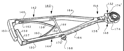
(00163 fn Figs. 17 and 18, insertion tool 140, which is preferably stainless
steel,
is used for insertion of the implant 116 of Figs. 14-16. Tool 116 has a pair
of
elongated arms 142 and 144. Arm 142 has a handle 146 at one end and a
jaw 148 at the opposite end. Arm 144 has a handle 150 and a jaw 152 at
opposite ends. An extension member 153 extends normal to arm 142 handle
146 at reinforcing gusset 155 which also serves as a stop to limit the motion
of the extension portion 159 when the handles are squeezed together.
Extension member 153 is made robust, e.g., increased thickness, to receive
insertion forces from a hammer (not shown). An extension member 157
extends from the end of handle 150 and has a portion 159 that overlies a
34
CA 02460028 2004-03-09
WO 03/037228 PCT/US02/34466
portion of the extension member 153. Extension member '! 57 is also robust
of increased thickness as compared to the respective arm 144. The overlying
portions of the extension members may abut or be closely spaced to transmit
an insertion force to both arms 142 and 144. A hammer blow on the
extension member 153 is transmitted to the jaw 148 via pivot mechanism 154
(and also to the jaw 152 via extension member157).
[00164] Pivot mechanism 154 comprises a pivot pin 156 which pivotally joins
the arms 142 and 144. The handles, pivot mechanism and jaws of the tool
140 may generally be mirror images of each other except as noted below.
Springs 158 and 160 interdigitized at joint 162 and are secured to respective
ones of the handles by screws or rivets 163 to urge the handles and arms 142
and 144 apart in a jaw opening and implant releasing direction. The arms
have bends 164 and have the shape of conventional pliers. A rod 166 is
pivoted to arm 142 and is threaded at end 168 which passes through a
passage in arm 144. A nut 170 is threaded to the end 168 to secure the arms
in a given desired implant gripping relation. When the arms are displaced
toward each other the jaws 148 and 152 are moved together in the direction
of the arrows, Fig. 18. Therefore, the nut 170 sets and/or applies the
gripping force. The flange on rod 166 limits the nut 170 travel and hence
maximum opening distance of the jaws.
[00165] In Fig. 19, representative jaw 148, which is identical to jaw 152 and
in
mirror image relation, includes a jaw extension 172. Extension 172 extends
from the arm 142 portion 142' cantilevered from the pivot mechanism 154
CA 02460028 2004-03-09
WO 03/037228 PCT/US02/34466
(Fig. 18). The jaw 148 has an implant gripping member 174 which extends
from extension 172. The member 174 terminates in tip end surface 176
which is distal the extension 172 and normal to the length dimension of the
member 174 in direction 178. Surface 176 abuts and mates with the wall
130 of the implant recess 124 to provide an insertion drive force upon receipt
of an insertion force on the arm 142 at extension 153. The member 174 has
a generally right semicircular cylindrical surface 180 wifih parallel saw
teeth
serration 182 formed by grooves . The jaw can be any shape and may or
may not be complementary to the recess gripping ' surface of the mating
implant. The surface 180 does not necessarily mate with surface 124 or 126
(Fig. 14).
[00166 For example, in Fig. 19a, the jaw 181 has a generally flattened surface
.
183 with a radius at each edge 189 that is serrated with serrations 185. In
Fig. 19b, the jaw 181 edges 189 tangentially contact the concave arcuate .
surface of the wall 124. The serrations are optional. Surfaces that transmit
insertion forces can be any shape, and not just flat, so long as they
adequately transmit these insertion forces.
[00167 The members 174, 174' of the two jaws 148, 152, Fig. 18, are inserted
into the respective implant 116, Fig. 14, recesses 124, 126 for holding and
insertion of the implant into the intervertebral disc space in direction 178.
Representative surface 180, Fig. 19, may mate with and may be
complementary to the recess 124 wall 124 surface, which may be semi-
cylindrical or other shapes. Such shapes are not critical. Tangential contact
is
36
CA 02460028 2004-03-09
WO 03/037228 PCT/US02/34466
sufficient for the gripping member to grip the implant. What is important is
that the gripping member contacts and grips the implant at the mating
gripping surface of the recess regardless of the mating surfaces are
complementary or tangential.
[00168] The two jaws 148 and 152 cooperate to grip the implant at its
recesses.
The tip surfaces 176 of the two jaws abut the corresponding walls of the
respective recesses such as walls 130 and 136 (Fig. 14). The nut 170 is
adjusted to set the gripping forces.
[00169] The handles146 and 150 are spread apart to release the implant 116
after insertion of the implant.
[00170] In Figs. 21-25, an alternative implant insertion tool 184 is shown for
insertion of the implant 116 of Figs. 14-16 and 20. Insertion tool 184
includes
an outer elongated tubular housing 186 which has spaced annular grooves
188 which serve as a gripping handle. Housing 186 at one end has an axially
extending cylindrical recess 190, Fig. 23. The housing 186 has an axially
extending bore 192 in communication with the recess 190. A larger diameter
axially extending bore 194 is in communication with bore 192 at one bore end
and with the opposite end 196 of the housing. The bore 194 terminates at
housing end 196 in a radially outwardly frusta-conical flared portion 198. The
housing flared portion 198 is generally square in its outer periphery as shown
in figure 21 and is larger in cross section than the remainder of the housing
186.
37
CA 02460028 2004-03-09
WO 03/037228 PCT/US02/34466
[00171 A rod 200 is located in bore 192 and has a hex head 202 at one end.
The rod 200 has threads 204 at its other end. The hex head abuts housing
shoulder 206 in the recess 190. Elongated jaw member 208 is located in the
bore 194. Member 208 has a threaded bore 210 which is engaged with the
threads 204 of rod 200. The member distal the bore 210 is formed with
bifurcated branches or arms 212, 214 which can flex with respect to each
other in the plane of the drawing sheet, Fig. 23, in directions 216. The arm
212 terminates at jaw 218 and arm 214 terminates at jaw 220. Jaws 218 and
220 may be mirror images and a description of jaw 218 is representative in
this case. This due to the fact that the recesses on opposite sides of the
implant may differ in shape, location and geometry.
[00172 Jaw 220 includes a rectangular in cross section intermediate member
222 extending from arm 214. Jaw implant gripping member 224 extends
from the member 222. Gripping member 224' extends from intermediate
member 222' attached to arm 212. The gripping members are generally
parallel to each other. The gripping members 224, 224' may have the shape
and configuration of the gripping member 174, Fig. 19, as discussed
according to a given implementation. The gripping members 224, 224'
engage the recesses 124, 126 of the implant 116, Fig. 14. The members
have the geometry to roughly mate with and function with the respective
recesses of the implants as described. The tips of the gripping members 224,
224' are used to abut the insertion surfaces of the implant recesses to insert
the implant into the disc space.
3~
CA 02460028 2004-03-09
WO 03/037228 PCT/US02/34466
[00173] The intermediate members 222 and 222' of the respective arms 214
and 212 normally are flexed apart a distance greater than the diameter of the
housing flared bore portion 198. The housing portion 198 mates with the
members 222 and 222' in a manner to prevent the jaw member from rotating.
S The normal position of the intermediate members forces them against the
flared bore portion 198 of the housing 186.
[00174 A knob 226 has a circular cylindrical drive section 228 which fits in
and
mates with the housing recess 190, Fig. 23. The drive section 228 has a hex
shaped socket 230 which reieasably mates with and receives the hex head
202 of the rod 200. The knob receives insertion forces from a hammer to
insert the implant if such forces are needed. The insertion forces are
transmitted to the opposite end of the tool to the distal tip surfaces of the
jaws.
[00175 Rotation of the knob 226 relative to the housing either draws the jaw
1S member 208 into the housing 186 or extends the jaw member beyond the
housing at end 196. When the jaw member is drawn into the housing bore
portion 198, the jaws 218 and 220 are moved together and spread apart
when the jaw member is displaced in the opposite direction out of portion 198.
[00176] The particular shape of the jaws, Fig. 19, is one arranged to mate
with
the recesses 124 and 126 of the implant 116. These jaws are reconfigured
for the implant insertion tools of figures 17 and 21 according to the shape
and
configuration of the recesses of the implants of the various embodiments of
Figs. 1, 5 8 and 11. In common with all such implants, the tools of figures 17
39
CA 02460028 2004-03-09
WO 03/037228 PCT/US02/34466
and 21 both grip the respective implant at their respective recesses and also
provide an insertion force to the implants at the insertion load receiving
surfaces of those respective recesses. In all cases, the insertion forces are
imposed on the bone implants through the lateral regions of the implant in the
direction of the insertion, primarily in the regions between the medullary
canal
and the implant outer peripheral surface. This minimizes the possible
damage to the implant if such forces were exerted more centrally in a
direction toward the medullary canal where the implant is the weakest.
[00177] In Fig. 27 the directions of the different anterior approaches are
shown
wherein the lateral approach is normal to the anterior approach and the
anterior/lateral approach may vary in the range of about 30-60°, or in
general,
between the anterior and lateral approach directions, medially between the
anterior and lateral approaches as shown by arrow 236.
[00178 In Figs. 28-36, an alternative embodiment of an insertion tool is
shown.
Tool 238 comprises an outer tubular housing 240, a shaft 242, a jaw section
244 and a thumb screw 246. The shaft 242, Fig. 30 has external threads 248
and a flange 250 at one end. The jaw section 244 has a threaded bore 252 in
portion 258 which receives the external threads of the shaft 242. The section
244 is bifurcated into jaws 254, 256 so that the jaws flex relative to the
portion
258 of the section 244, directions 260, Fig. 31. The shaft 242 is threaded
into
the threaded bore 252 which adjusts the length of the shaft and jaw section.
[00179 The tubular housing 240 has a longitudinal bore 262 in which the shaft
242 and jaw section are passed through. The housing 240 has an opening
CA 02460028 2004-03-09
WO 03/037228 PCT/US02/34466
264 which receives the threaded thumb screw 246 which has an interns!
thread 245. The internal screw thread 245 of screw 246 receives
therethrough the threads of the threaded shaft 242.
[001801 Rotation of the screw 242 selectively displaces the shaft 242 jaw
section 244 combined unit in and out of the bore 262 of the tubular housing
240. The housing 240 has a taper 266 at an enlarged end 268. The taper
266 receives the outwardly flared jaws 254 and 256. As the jaws move in
and out of the bore 262 of the housing the taper 266 forces the jaws closed
as they move into the housing bore 262 and permit them to spread apart as
they move out of the bore 262. The jaws 254 and 256 may have a bend
such as bend 230 of the jaws of the tool 9 84', Figs. 24 and 25. Rotation of
the
thumb screw thus determines and sets the spaced apart distance of fihe jaws
254 and 256 to grip the implant 270 via its recesses as described above and
below herein, such as implant 116 (Fig. 14) and so on.
[00181] In Figs. 37-40, implant 272 is a wedge shaped cortical bone ring but
may be made of other materials as discussed above. The implant 272 has a
flat anterior end surface 274 which identifies to the surgeon that this is the
anterior end on anterior/posterior plane 276. Recesses 278 and 280 are
aligned on insertion axis 282 which is in the range of approximately 30-
60° to
the plane 276. See Fig. 27, arrow 236 defining this insertion direction range.
The recesses 280, 278 have insertion load receiving surfaces 284, 284',
respectively. Any of the insertion tools described above can be used to insert
this implant.
41
CA 02460028 2004-03-09
WO 03/037228 PCT/US02/34466
[00182] The implant 286 of Figs. 41-44 is substantially the same as implant
272
of Fig. 37 except that recesses 287 and 288 are of different sizes and
locations as shown in Fig. 41. The recesses are different distances 289, 289'
from the end 290. In this case, the tools described above have jaw tips that
mate with the insertion surface locations of the implant 272 insertion load
receiving surfaces 291, 291'. The anterior end 292 is identifiied by a flat
surface. Further, the gripping surface 293 of recess 287 is arcuate and the
gripping surface of recess 288 is flat
[00183] In Figs. 45-48, implant 294 has recesses 296, 296' and a flat surface
298 at the anterior end. This implant is inserted in the lateral direction 300
(see Fig. 27). The recesses have flat insertion load receiving surfaces 302
and arcuate gripping surfaces 304
[00184] In Figs. 49-52, implant 306 is also for insertion in the lateral
direction
300. Recesses 308 and 310 differ in size and location as shown. Recess
310 forms the anterior face of the implant in the anterior-posterior
direction,
arrow 312. The mating insertion tool has jaws that are arranged to apply
insertion loads to surfaces 309, 309' of the respective recesses while
gripping
the respective gripping surfaces 311, 311' thereof, the gripping surfaces
being
generally parallel to the lateral direction of insertion 300 and the insertion
load
receiving surfaces 309, 309' being generally parallel to the
anterior/posterior
direction 312.
[00185] In Figs. 53-56, a C-shaped implant 314 is described in more detail in
certain of the applications and patents mentioned in the introductory portion,
42
CA 02460028 2004-03-09
WO 03/037228 PCT/US02/34466
incorporated by reference herein. The implant 314 is formed from transverse
cuts in a long bone such as the femur or other bones as noted in the above-
noted patents and applications. The implant 314 is preferably cortical bone
but may be other materials, natural or synthetic as also mentioned previously
herein above.
[00186] The implant 314 is made from approximately one half of a cortical
bone ring. The implant 314 has a concave surface 316 formed for example
by the medullary canal of the bone. The implant 314 has a flat anterior end
surface 318 and a flat posterior end surface 320. The implant 314 has saw
teeth 322 on opposing top surface 324 and bottom surface 326 and
chamfered surfaces 328 at the anterior end to facilitate insertion in
direction
330, Fig. 53.
[00187] Implant 314 has two coplanar side surfaces 332, 334, Fig. 55, at the
opposite respective posterior and anterior ends of the surface 316. The
surfaces 332, 334 extend in the anterior-posterior direction 330 generally
parallel to the longitudinal axis 336 of the implant. The implant 314 has a
curved convex peripheral surface 338.
[00188] Implant 314 has a recess 340 in surface 338 adjacent to and 'spaced
somewhat from the flat posterior surface 320. The recess 340 has a semi-
cylindrical insertion tool gripping surface 342 and an insertion tool
insertion
load receiving surface 344. The surface 344 receives insertion forces in the
insertion direction 330 imparted by a tool to be described. This tool grips
the
surface 342 in a manner to be explained.
43
CA 02460028 2004-03-09
WO 03/037228 PCT/US02/34466
[00189 In Figs. 58 and 60, tool 346 is similar to the insertion fiool
disclosed in
the aforementioned copending application serial no. 60/246,601 noted in the
introductory portion and incorporated by reference herein. Reference should
be made to that application for more details on this tool. In the figures,
too!
346
(00190 In Figs. 58 and 60, implant insertion tool 346 comprises an elongated
shaft 348 defining longitudinal axis 350 and having a proximal end 352 and a
distal end 354. The proximal end 352 comprises a solid metal preferably
stainless steel handle 356 having a knurled or roughened gripping surface.
The proximal end of the handle is formed into an enlarged disc-like grip
member 358. Approximately medially the shaft 348 and extending toward the
distal end is a bifurcated portion comprising bifurcated shaft portions 360
and
362 having a gap 364 therebetween.
[00191 The shaft portion 360 has a through bore 366. The shaft portion 362
has a threaded bore 368 aligned with bore 366 on axis 370. The threaded
bore 368 has a larger diameter than bore 366, which is a smooth surface
circular cylindrical bore. A circular recess is formed in a surface of the
shaft
portion 360 aligned on axis 370 and concentric therewith as are bores 26 and
28.
(00192 A displacement member 371 includes a shank portion 372 and a knob
374 connected to a lever 384. Shank portion 372 comprises a threaded stud
376 attached to a smooth waited circular cylindrical shank 378 as a one piece
metal element which may also be stainless steel. The stud 376 is larger in
44
CA 02460028 2004-03-09
WO 03/037228 PCT/US02/34466
diameter than shank 378. Shank 378 is rotatably and slidably mounted in
bore 366 and can axially displace in this bore along axis 370. The stud 376 is
threaded to bore 368. The threaded stud 376 has a shoulder 380 at the
shank 370. This shoulder abuts the shaft portion 360 in the gap 364. The gap
364 may be about 1.5 mm.
[00193] Knob 374 is attached to the shank 378 by welding or other fixed
securing arrangement after the shank 378 is attached to shaft portion 360 and
the stud 376 is engaged in bore 368. The shoulder 380 of the shank portion
372 is located in the gap 364 at the time the shank 378 is attached to the
knob 374. The shank 378 is received in bore 382 of the knob 374. The knob
374 and shank portion 372 when fixed then rotate as a unit when the knob
374 is rotated.
[00194] The knob 374 is attached to elongated lever 384 to facilitate rotation
of
the knob. The knob has a right circular cylindrical boss 386 which engages,
and rotates in a circular cylindrical recess (not shown) in the shank portion
360. The portion 360 is captured between the knob boss 386 and the
shoulder 380 of the displacement member 33. The lever 384 helps the
surgeon in attaching or releasing the implant 314 thereto.
[00195] In operation of the displacement member 371, rotation of the knob 374
axially displaces the stud 376 in the shaft portion 362 along the axis 370.
This moves the shoulder 380 against the shank portion 360 along the axis
370. If the member 371 is displaced toward the shaft portion 360, the
shoulder 380 will spread the shaft portions 360 and 362 apart widening the
CA 02460028 2004-03-09
WO 03/037228 PCT/US02/34466
gap 364. The shaft portions 360 and 362 bend relative to each other due to
flexure of the material at their junction and/or also along the length of the
shaft
portions.
[00196] The location of the flexure depends upon the thickness of the shaft
portions. Flexure also may occur at the junction between the two shaft
portions. This flexure is resilient so that any bending of the shaft portions
results in a bias force tending to return the shaft portions to their
quiescent
position. This bias force will not cause the shaft portions to return to their
quiescent position by itself due to the presence of the displacement member
371. The displacement member via its knob must be rotated to do so. The
displacement member 371 actively opens and closes the two shaft portions
360 and 362. In the closing position, the knob 374, when displaced toward
portion 362, forces the captured flexed portion 360 to its quiescent position.
(00197] Displacement of the displacement member 371 toward shaft portion
362 moves the boss 386 abutting the shaft portion 360 in the mating recess
toward the shaft portion 362 and thus displaces the shaft portion 360 also
toward shaft portion 362 closing the gap 364.
[00198] A stop member 388 comprises a shank 390 and a head 392. The
shank 390 is threaded at threaded stud end 394 and is smooth at the head
392 end . The threads of the shank 390 are attached to mating threads in the
shaft porfiion 362 and the head 392 is received in a recess in the shank
portion 360. The shank 390 smooth portion is received in a mating bore in
the shaft portion 360.
46
CA 02460028 2004-03-09
WO 03/037228 PCT/US02/34466
[00199] In operation of the stop member 388, the member 388 is threaded into
the shank portion 362 a distance so that the head 392 is spaced from the
bottom of the recess (not shown) in the portion 360. The shank portions 360
and 362 can spread apart a distance until the head abuts the bottom wall of
the recess in the portion 360. This limits the motion of the shaft portions
and
the amount they can spread apart. This prevents the shaft portions from
being spread apart too great a distance which may be undesirable in certain
implementations, conditions or uses of the tool 346.
[00200] The tool 346 has a pair of jaws 395, 397 respectively formed at the
end
of the shaft portions 360 and 362. Jaw 395 comprises a one piece integral
rectangular in cross section extension 396 extending from shaft portion 360.
Jaw 397 comprises a rectangular in cross section extension 398 extending
from shaft portion 362. Both extensions extend in the distal direction to the
right in Fig, 60. The extension 396 is dimensioned to engage the recess 340
in the implant 314, Fig. 57. The extension 398 is dimensioned to abut the flat
surfaces 332 and 334 at flat gripping surface 399 (Fig. 59) gripping the
implant at these surfaces and bridges the concave surface 316 of the implant
314, Fig. 57.
[00201] The extension 396 has a flat rectangular tip 400 abutting the implant
insertion load receiving surface 344 of the recess 340 (Figs. 53-55), and
grips
the implant at the implant recess gripping surface 342. The extensions may
be relatively thin elements, e.g., about 2 mm thick. In Fig. 61, the extension
396 may be generally rectangular with radii R at its corners abutting the
47
CA 02460028 2004-03-09
WO 03/037228 PCT/US02/34466
recess surface 342 of the implant 314. In the alternative, the extension 396
may be complementary to the recess surface 342 contour. In a further
alternative, the exfiension may have a triangular or curved surface which
tangentially contacts the recess surface 342 in a line contact. In all cases,
the
S tip 400 is blunt for imparting an insertion force on the recess insertion
load
receiving surface 344.
[00202] The jaws 395 and 397 each have a shoulder 406 and 408, respectively,
extending normal to the extensions 396 and 398. The shoulder 404 may abut
the implant 314 posterior surface 320, Fig. 57. The shoulder 406 is spaced
from the implant surface 320. The shoulder 404 forms a further flat insertion
load receiving surface for insertion of the implant into the disc space. The
use
of the shoulder 404 as an insertion wail is optional.
[00203] fn Fig. 62 a further implant 408 is formed of bone or other material
and
is rectangular in transverse section. The implant 408 has tapered top and
1S bottom surfaces 410 and 412 forming it into a wedge. A recess 414 of the
type described above for the different implants is in one or both opposite
sides of the implant. The recess may have a curved or flat gripping surface
and has a flat insertion load receiving surface for receiving the tip of the
insertion tool jaw gripping member.
[00204] Figs. 63-66 illustrate a further implant 416 also of C-shape as the
implant 314 of Figs. 53-56. The implant 416 however has flat parallel side
surfaces 418 and 420 which lie in different planes. Reference numerals that
are the same refer to the same parts in the implants 416 and 314, whereas
48
CA 02460028 2004-03-09
WO 03/037228 PCT/US02/34466
reference numerals with primes but otherwise the same refer to similar parts.
The surface 418 has a recess 422 with normal insertion wall surface 424 and
gripping surface 426. The insertion direction 428 is in the posterior-anterior
direction.
[00205] In Fig. 67, implant 416 is inserted by insertion tool 346' via jaws
396
and 398'. Jaw 398' fits into the recess 422 for gripping the surface 426 and
insertion Toad receiving surface 424, Fig. 65. Jaw 396 engages the recess
340 which may be the same as recess 340 in implant 416, Figs. 63-66. Both
jaws 396 and 398' apply insertion loads to the implant on opposite sides. The
shoulder 430 of jaw 398' may also insert the implant at end surface 320'.
[00206] In Fig. 69, anterior approach implant 500 according to a further
embodiment has the same general shape and dimensions as the implant 10
of Figs. 1-4. except for the recesses 502 and 504. Recesses 502 and 504
are of generally the same shape and dimensions and not necessarily mirror
images of each other because of the uneven geometry of the bone geometry.
Recesses 502 and 504 form channels that extend generally normal to the
respective top and bottom surfaces 501, 503 and are on opposite sides of the
peripheral surface 506.
[00201] Representative recess 504 has an inner portion 508 which is generally
semicircular in cross section. Wall portion 508 is continuous with planar.
impact wall 510 which is on the posterior side of the recess 504 and is
generally normal to the longitudinal anterior-posterior direction axis 512 of
the
implant. Wall 508 has a further side wall 514 which extends continuous with
49
CA 02460028 2004-03-09
WO 03/037228 PCT/US02/34466
the bottom wall portion 508. Wall 514 extends on the anterior side of the
recess 504 toward the outer peripheral surface 506 inclined at an acute angle
to the axis 512 and toward the anterior flat surface 516. The recesses 502
and 504 are linear as shown in Fig. 70 and approximately equally spaced
from axis 512 depending upon the symmetry of the implant about axis 512.
The recesses also are in communication with the implant 500 top and bottom
surfaces 501 and 503. Again, like above, the placement of the dovetail cut-
outs wil( depend on the natural bone geometry. The dovetails will be placed to
minimize the impact force through the interior portion of the implant over
fihe
medullary canal and, therefore, will not necessarily be mirror images.
[00208] The wall 510 receives insertion impact loads applied by the insertion
tool 518, Figs. 73, in direction 505 a manner similar to that described above
for the implant 10 of Fig. 1, implant 50 of Fig. 5 and so on. Those implants
are inserted by the tools of Figs. 17 and 28, for example.
[00209] The mating jaws 520', 522', Figs. 73 and 74, of the insertion tool 518
have complementary dimensions and shapes to fit in the respective recesses
502 and 504. The wall portion 508 and wall 510 receive and abut the tips
520, 522, Fig. 73, of the insertion tool 518 jaws 520' and 522', respectively.
These jaw tips have surfaces in contact with the surfaces of these recess
walls providing the primary forces needed to insert the implant into the
intervertebral space. The wall portion 508 receives the gripping forces of
tips
520 and 522 in a direction normal to the axis 512. These gripping forces grip
the implant during insertion. The tips 520 and 522 have end surfaces 524
CA 02460028 2004-03-09
WO 03/037228 PCT/US02/34466
and 526 normal to the longitudinal axis 528 of the insertion tool 518. The end
surfaces 524 and 526 are used to impact the impact receiving surfaces of
walls 510 of the implant, Figs. 72, 74.
[00210] In Fig. 74, the tips have semi-cylindrical surfaces 530 and 532 which
preferably mate with the recess bottom wall portion 508. The tips may have
surfaces 530 and 532 of radii smaller than the radii of the portion 508. While
the surface of portion 508 may be a portion of a circle, it may have any
curvature as desired. The tips 520 and 522 have a rear surface 532, 534
respectively which may abut the surface 514, Fig. 72, of the recesses 502
and 504, respectively.
[00211] The jaws 520' and 522' may be used with an insertion tool such as tool
;
140, Fig. 17, or tool 238, Fig. 28 or a tool of any other suitable
configuration
for impact insertion of the implant.
[00212] In Figs. 75-77, implant 540 is the same as implant 50 of Fig. 5, and
in
the alternative, may be constructed as any of the other implants of Figs. 1,
8,
11, 14 and so on. Implant 540 has a through bore 542 between the anterior
planar surface 544 and central opening 546 on longitudinal axis 548. The
bore 542 may be threaded or unthreaded. The bore 542 receives the stud
438 of the tool 430, Fig. 68. The stud is preferably not threaded for use with
an unthreaded bore 542.
[00213] In this way, the stud and bore serve to stabilize the orientation of
the
implant to the insertion tool while permitting the insertion tool jaws to
apply the
entire insertion impact forces against the implant in the mating implant
51
CA 02460028 2004-03-09
WO 03/037228 PCT/US02/34466
insertion tool jaw receiving recesses. When the bore 542 and stud are not
threaded, there may be some clearance between the two so that all of the
impact forces are transmitted to the jaws and implant impact receiving
recesses. The bore 542 may be about 3.18 mm (0.125 inches) in diameter.
The implant of Figs. 69 and 75, as also the other implants described above of
these configurations, may have an anterior end height in the range of about
11-19 mm and a length, and in Figs. 70 and 76, from left to right in the
figures,
in ranges of about 24-27 mm and 28-30 mm. The implants may have a
transverse width normal to the longitudinal axes thereof of about 24-28 mm.
The top and bottom surfaces converge at an angle of about 8°. The
posterior
insertion end of the implants is chamfered as shown.
[00214] Figs. 78-82 illustrate a spinal implant insertion tool 550 according
to a
further embodiment of the present invention. The tool 550 may have the
overall actuating mechanism configuration of tool 140, Figs. 17-19, but has ,
implant gripping jaws 552 and 554 with a different configuration as shown in
Figs. 78-82. In the alternative, still other actuating mechanisms such as
shown herein or as known in the prior art may be used with the implant
insertion jaws 552 and 554 of Figs. 78-82.
[00215] The tool 550 implant gripping jaws 552 and 554 are preferably
identical
in this implementation and in mirror image relation, but may differ from each
other in other implementations. Representative jaw 554 extends from arm
556 of tool 550. Jaw 552 extends from arm 558. The arms 556 and 558, by
way of example, are pivotally connected (not shown) as shown for tool 140,
52
CA 02460028 2004-03-09
WO 03/037228 PCT/US02/34466
Fig. 17, and have the same or similar handle construction (not shown) as tool
140. Jaw 554 is representative of jaw 552 in mirror image relation and
therefore jaw 552 wiN not be described separately.
(00216] Jaw 554 extends from arm 556 via a tapering jaw section 560 which
converges in cross section area toward the implant gripping member 562.
Jaw 552 has a gripping member 562' which is identical to but in mirror image
relation to gripping member 562. Section 560 is rectangular in cross section
and has a relatively thin thickness t1 and a broad width w1. The gripping
member 562 has an arcuate peripheral implant gripping surface 564. The
surface 564 terminates at flat opposite side walls 566, 566'. The surface 564,
in side elevation as shown in Fig. 82, is also arcuate and formed by a radius
between the element 562 end wall 568 and the opposite inclined wall 670
facing and terminating at the arm section 560. Wall 570 is triangular in plan
view, Fig. 81, and comprises two surfaces inclined at angles relative to each
.
other as they extend to and between walls 566, 566'. The wall 570 is inclined
from the element tip surface 564 to its base region at surface 572 of the arm
section 560, Fig. 82. The implant gripping member 562 thus comprises a
number of complex curved surfaces projecting upward from the arm surface
572 and extending between the side walls 566, 566' and end wall 568.
(00217] Implant 574, Figs,. 83-87, has recesses 576, 576' which are identical
but in mirror image relation. The recesses 576, 576' mate with and receive
the insertion tool 550 respective corresponding jaw gripping members 562,
562', Figs. 78-82. The implant 574, except for the recesses 576, 576', may
53
CA 02460028 2004-03-09
WO 03/037228 PCT/US02/34466
be identical to the implant 500, Fig. 69, for example, or identical to any
other
of the disclosed implants herein except for the recesses 576, 576'. The
recesses 576, 576' are complementary to the respective gripping members
562, 562' of the insertion tool 550 and generally have the cross section shape
of recesses 502, 504 of implant 500, Fig. 69. The difference between
recesses 502, 504 and recesses 576, 576' is that the recesses 576, 576' are
spaced from the bottom surface 578 and top surface 580 of the implant 574.
The recesses 576, 576' face and are near the anterior end 582 of the implant,
which end is a fiat surface.
[00218 In operation, the implant gripping members 562, 562' of jaws 552 and
554, Fig. 78, are inserted into the recesses 576, 576' of the implant 574,
Fig.
83. The recesses 576, 576' are formed as dimple depressions in the outer
peripheral side wall of the implant 574. The gripping members 562, 562' are
inserted into the respective corresponding depressions and are surrounded ...
on all sides by the side wail of the mating recess 576, 576'.
[00219] The end wall surFace 568 of the gripping members serves as an
insertion impact surface as described above for impacting against the mating
recess 576, 576' surface to insert the implant into the disc space. However,
the member 562 is surrounded by the recess 576 walls which enables the
member 562 to firmly grip the implant in all directions. For example, in the
implant 500 of Fig. 69, its recesses 502 and 504 are in communication with
the bottom and top surfaces of the implant and has a surface parallel to the
anterior/posterior axis.. Thus the implant could slide off of the jaws in the
54
CA 02460028 2004-03-09
WO 03/037228 PCT/US02/34466
anterior direction. The same is true of the implant 10 of Fig, 1. In the case
of
the implant 574 of Fig. 83, however, the implant can not slip off of the jaw
elements 562 in any direction. This permits the surgeon to manipulate the
insertion tool 550, Fig. 78, and gripped implant 574 in any direction even
after
the implant is inserted into the disc space without the implant moving
relative
to the jaw members 562. This is important in the situation where the implant
needs to be maneuvered somewhat after it is inserted into the disc space and
is compressed by the adjacent vertebrae after the distraction of the vertebrae
is removed. The vertebrae provide increased resistance to such implant
1'0 maneuvering which might cause jaws of certain of the tools disclosed
herein
to be less able to apply sufficient force to move the implant in certain
directions. This is especially true wherein the recesses have surfaces
parallel
to the anterior/posterior axis such as implant 10, Fig. 1, for example. This
will
not occur with the tool 550 of Fig. 78 and implant 574 of Fig. 83. The recess
configuration of implant 550, Fig. 78, may be used in any of the embodiments
of the implants disclosed herein
[00220 It will occur to one of ordinary skill that modifications may be made
to
the disclosed embodiments without departing from the scope of the invention
as defined in the appended claims. The disclosed embodiments are given by
way of illustration and not limitation. For example, while circular semi-
cylindrical jaws are disclosed for mating with complementary shaped
recesses, other convex shapes may also be used such as oval and other non-
CA 02460028 2004-03-09
WO 03/037228 PCT/US02/34466
circular surfaces as well as planar surfaces for use with the implants of
Figs.
1, 5, 8 and 11.
[002211 The surfaces of all such jaws engaging the implant may be knurled or
have serrations as described or other roughened surfaces to better grip the
implant. These surfaces may also be smooth as desired. Still other insertion
tools of different configurations than those shown may be used with the
recesses of the different disclosed implants, the important aspect comprising
the shape and configuration of the jaws rather than the particular mechanism
for operating the jaws. In all cases, the jaws of the insertion tool have tips
arranged to apply insertion loads against the mating insertion load receiving
surface of the corresponding implant recess. In some cases, the jaws may
have flat implant gripping surfaces for gripping flat recess surfaces
extending
in the anterior-posterior direction. But, in all cases, the recesses each have
an insertion load receiving surface that is generally transverse to the
anterior-.
posterior direction for mating with the jaw tips.
[00222] In a further embodiment, the insertion tool may have a threaded rod
that mates with a threaded bore in the implant for holding the implant during
insertion. Such a rod is shown for example in US patent no. 5,522,899 to
Michelson incorporated by reference herein. in this case, the insertion too!
jaws have tips that engage the insertion load receiving surfaces of
corresponding recesses in the implant plug. The jaws however do not grip fihe
implant plug which gripping function is carried out by the threaded rod. Such
a threaded rod is also disclosed in copending application serial no.
56
CA 02460028 2004-03-09
WO 03/037228 PCT/US02/34466
60/246,297 mentioned in the introductory portion and also incorporated by
reference herein.
[00223] An example of such a tool is also shown in Fig. 68 wherein insertion
tool 430 is similar to tool 140 of Fig. 17 except as modified below, the parts
with the same numbers being the same. The handle 432 has an extension
434 which receives and supports a rod 436, which may be rotatable or move
just in translation. Rod 436 has a threaded stud 438. The jaws 440 and 442
are use to insert a received implant plug 444 at mating recesses 446 (one
being shown). However, the jaws 440 and 442 do not grip the plug 444. The
rod 436 rotatably passes through a mating bore (not shown) in the pivot
member 448 and axially extending channels (not shown) in the arms 450 and
452 connected to the handles 432 and 432'. The channels permit the arms
to pivot about pivot member 448. The rod 436 stud 438 engages a threaded
bore 454 in the plug 444, holding the plug during insertion. It should be
understood that the implants that are inserted laterally or anterior/laterally
may
be inserted on either side of the patient, the particular orientation shown in
Fig. 27 being by way of example.
[00224] It should be understood that the term "anterior/posterior" axis and
positions are used herein for purposes of reference and are not limited to
spinal bone posterior and anterior positions. These terms are used herein
and in the claims as terms of reference for relating the various locations of
an
implant to the recipient bone site. While the implants made of bone are
described as having weak sections that are aligned with a central chamber
57
CA 02460028 2004-03-09
WO 03/037228 PCT/US02/34466
formed in the implant and stronger sections or regions that are aligned with
the implant material adjacent to the chamber, it should be understood thafi
synthetic implants may also have relatively weak and strong regions therein.
The insertion recesses provided such implants are provided in the stronger
regions to preclude insertion damage to the implants that might otherwise
occur in the presence of impact or other insertion forces.
[00225 In addition, while the implants described herein are preferably for use
in
spinal applications, if will occur to those of ordinary skill that the
principles of
the present invention may be applied to implants into bone that are not spine
related. Such applications include implants where impact or insertion loads
are required creating sufficient insertion forces that could damage the
implant
during insertion.
58