Note: Descriptions are shown in the official language in which they were submitted.
CA 02460404 2004-03-09
RETRACTABLE RULE ASSEMBLY WITH IMPROVED BLADE OPENING
Field of the Invention
[0001) The present invention relates to retractable mle assemblies.
Background of the Invention
[0002] Figure 1 illustrates the blade opening of a prior art retractable rule
assembly
wherein the housing is formed of a plastics material. The rule assembly is
generally
indicated at 300 and the housing is generally indicated at 302. The housing
302 includes a
blade opening 304 through which an elongated metal blade extends. The blade is
not shown
far purposes of clearly showing the blade opening 304. A spring-driven reel
306 is mounted
in the housing 302 and the blade is wound thereon with its extended portion
extending
through the blade opening 304. During use of the rule assembly, the blade is
extended from
the reel 306 through the blade opening 304 for purposes of taking
measurements, and then is
retracted automatically by the spring driving the reel 306. During the
repeated usage over
time, the lateral side edges of the blade can come into contact with the
lateral side edges of
the opening 304, particularly during retraction by the spring. Because the
spring retracts the
blade at a relatively high speed, and the blade is formed from a metal, which
is significantly
harder than the plastics material of the housing 302, the blade's lateral side
edges can wear
grooves 308 into the plastics material at the lateral side edges of the
opening 304.
[0003] As shown in Figure l, these grooves can become relatively deep over
time.
Specifically, the blade initially forms a slight groove during its initial
usage, and over time
the blade tends to "find" this groove and repeatedly wear the same groove to
increased depth,
rather than uniformly wearing the entire height of the lateral sides edge. As
an analogy, this
can be compared with the manner in which one cuts lumber with a saw - first
the user moves
the saw over the edge of the uncut lumber to form an initi<~l groove, and then
can cut freely
with more power because the initial groove will guide the saw as the cutting
depth increases.
[0004] This formation of grooves 308 can be problematic for a number of
reasons.
For example, as the blade rides in a formed groove 308, the measuring indicia
on the blade
edges can be worn off by the upper surface of the grooves, which makes it
difficult to take
proper measurements. Also, as the blade rides in the groove, friction is
created, which
provides additional resistance to blade retraction. To offset this additional
resistance, a larger
more powerful spring may be needed, which adds cost. In addition, these
grooves 308 can
create "fulcrum points" about which the extended portion of the blade can bend
sharply
30266007v1 1
CA 02460404 2004-03-09
during retraction. Specifically, in some rule assemblies the; blade opening is
designed to be
vertically higher than the blade itself to accommodate some vertical movement
of the blade to
minimize the chances of sharp bends in the blade as it retracts. However, when
the blade
rides in a groove 308, the groove 308 prevents such vertical movement of the
blade, and thus
can create a point about which sharp bends occur. Sharp bending of the blade
is undesirable,
because over time it can lead to blade fatigue and failure.
Summary of the Invention
[0005] The present invention provides solutions to protect the lateral side
edges of the
blade opening from wear.
[0006] One aspect of the present invention provides a retractable rule
assembly
comprising a housing having a blade opening, the blade opening having two
lateral sides
provided by a plastics material having a hardness; and a reel rotatably
mounted in the
housing. An elongated blade is formed of a ribbon of metal having a pair of
opposing lateral
side edges. The blade is extendable outwardly through the lblade opening of
the housing with
the lateral side edges thereof adjacent the lateral side edges of the opening.
The blade has a
concavo-convex cross-sectional configuration when extended from the housing
and also has
measuring indicia on the concave side thereof. A spring is constructed to
rotate the reel in the
housing in a direction to wind up the elongated blade onto the reel in a
flattened cross-
sectional configuration. The rule assembly of this aspect: of the invention
also comprises
wear resistant structure comprising a wear resistant material having a
hardness greater than
the hardness of the plastics material. The wear resistant stnxcture is located
at least at each of
the lateral sides of the blade opening to substantially protect the plastics
material at the
opening's later sides from wear by the lateral side edges of t:he blade.
[0007] Another aspect of the invention provides a retractable rule assembly
comprising a housing having a blade opening, the blade opening having two
lateral sides
provided by a plastics material; and a reel rotatably mounted in the housing.
An elongated
blade is formed of a ribbon of metal having a pair of opposing lateral side
edges. The blade
is wound on the reel and is extendable outwardly through the blade opening of
the housing
with the lateral side edges thereof adjacent the lateral side:> of the
opening. The blade has a
concavo-convex cross-sectional configuration when extended from the housing
and also has
measuring indicia on the concave side thereof. A spring is constructed to
rotate the reel in the
housing in a direction to wind up the elongated blade onto the reel in a
flattened cross-
sectional configuration. This rule assembly of this aspect of the invention
also comprises
30266007vi
CA 02460404 2004-03-09
wear resistant structure comprising metal. The wear resistant structure is
located at least at
each of the lateral side edges of the blade opening to substantially protect
the plastics material
at the opening's lateral sides from wear by the lateral side edges of the
blade.
[0008] Another aspect of the invention provides a retractable rule assembly
comprising a housing having a blade opening having two lateral sides provided
by a plastics
material and a reel rotatably mounted in the housing. An elongated blade is
formed of a
ribbon of metal having a pair of opposing lateral side edges. The blade is
extendable
outwardly through the blade opening with the lateral side edge thereof
adjacent the lateral
sides of the opening. The blade has a concavo-convex cross-sectional
configuration when
extended from the housing and has measuring indicia on the concave side
thereof. A spring
is constructed to rotate the reel in the housing in a direction to wind up the
elongated blade
onto the reel in a flattened cross-sectional configuration. Rollers are
rotatably mounted at
least at each of the lateral sides of the blade opening to substantially
protect the plastics
material thereat from wear by the lateral side edges of the blade.
[0009] Other objects, features, and advantages of the present invention will
become
apparent from the following detailed description, the accompanying drawings,
and the
appended claims.
Brief Description of the Drawings
[0010] Figure 1 is a front close-up view of a blade opening in a prior art
rule
assembly;
[0011] Figure 2 is front perspective view of a rule assembly constructed in
accordance with the present invention;
[0012] Figure 3 is a front elevated view of the rule assembly of Figure 2;
[0013] Figure 4 is a profile view of the rule assernbl;y of Figure 2;
[0014] Figure 5 is a cross-sectional view taken along line 5,6-5,6 of Figure 3
with the
blade fully retracted;
[0015] Figure 6 is a cross-sectional view taken along line 5,6-5,6 of Figure 3
with the
blade fully extended;
[0016] Figure 7 is a cross-sectional view taken along line 7-7 of Figure 4;
[0017] Figure 8 is a sectional view of the blade in its concavo-convex
configuration;
[0018] Figure ~9 is a sectional view of the blade in its flattened
configuration;
[0019] Figure 10 is a partial cross-sectional view taken along lines 10-10 of
Figure 7;
[0020] Figure 11 is a front elevated view of the insert mounted in the blade
opening;
30266007v1
"' CA 02460404 2004-03-09
[0021] Figure 12 is a rear elevated view of the insert mounted in the blade
opening;
and
(0022] Figure 13 is a perspective view of the insert taken from the front
thereof;
[0023] Figure 14 is a front elevated view of an alternative rule assembly; and
[0024] Figure 15 is a front elevated view of a second alternative rule
assembly.
Detailed Description of the Illustrated Embodiment
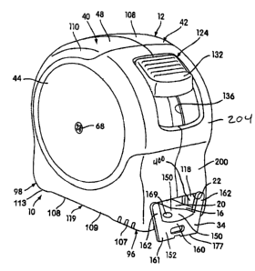
(0025] FIGS. 2-4 show an exterior view of a rearactable rule assembly that is
generally designated 10 and is constructed according to the principles of the
present
invention. The rule assembly 10 includes a housing assembly 12 and a reel 14
that is
rotatably mounted inside the housing assembly 12 (best seen in the cross-
sectional views of
FIGS. 5-7). The reel 14 is mounted in the housing assembly 12 by a reel
spindle 15 that is
secured within the housing assembly 12 (FIGS. S-7). An elongated tape rule
blade 16 is
mounted on the reel 14.
(0026] The blade 16 is formed of a ribbon of metal, the preferred metal being
steel,
and the top concave surface of the blade is printed with measuring indicia in
the form of
measuring lines and digits (not shown) for measuring lengths and distances.
One longitudinal
end 18 of the blade 16 is connected to the reel 14 or spring 32 and a second
longitudinal free
end 20 of the blade 16 extends generally outwardly of the reel 14. The blade
16 is extendible
generally from a position tangential of the reel 14 outwardly through a blade
opening 22
provided in the housing assembly 12 (as shown, for example;, in FIG. 5).
[0027] The reel 14 may be made of a molded plastic and is provided with slots
or
openings 24, 26 in a central cylindrical wall portion 28 thereof. The one end
18 of the blade
terminates in a hook-like structure 30 that connects to the spring 32 or that
hookingly engages
an edge of the wall portion 28 of the reel 14 at opening 24 to connect the end
18 of the blade
16 (FIGS. 5 and 6). The construction of the reel 14 is not essential and any
configuration or
construction may be used.
[0028] A coil spring 32 is connected between the housing assembly 12 and the
reel 14
to rotate the reel 14 with respect to the housing assembly 12 in a direction
to wind the
elongated blade 16 about the reel when the blade 16 is extending outwardly of
the blade
opening 22. The coil spring 32 is generally enclosed within the central wall
portion 28 of the
reel 14 (FIGS. 5-7). One longitudinal end 35 of the coil spring 32 connects to
the blade 16 or
hookingly engages an edge of the wall portion 28 of the reel 14 that defines
the opening 26; a
second longitudinal end 37 of the blade 16 hookingly engages the spindle 15.
The spindle 15
30266007v1 4
' CA 02460404 2004-03-09
is rigidly mounted to the housing assembly 12 in a manner considered in detail
below.
Preferably the spring 32 is a thin, flat ribbon of metal, the preferred metal
being steel. The
construction of the spring 32 and the manner in which it is connected between
the reel 14 and
the housing 12 are not essential and any construction or configuration may be
used.
[0029] The blade 16 is generally movable between a fully retracted position
within
the housing assembly 12 and a fully extended position. The fully retracted
position of the
blade 16 is shown in FIG. 5 and the fully extended position of the blade is
shown (in
fragmentary view) in FIG. 6. It can be appreciated from a comparison of FIG. S
and FIG. 6
that as the blade is unwound from the reel 14, the coil spring 32 is wound
around the rigidly
fixed spindle 15. This winding of the spring around the spindle stores energy
in the spring to
provide spring powered rewinding of the blade 16 around the reel 14 when the
extended
blade is released.
[0030] The blade 16 is constructed of a ribbon of sheet metal that is shaped
during the
manufacturing to have a normal or memory configuration that has a generally
arcuate or
concavo-convex transverse cross-section. When a portion of the blade 16 is
wound about the
reel 14, the wound portion has a flat transverse cross-section (FIGS. 7 and 9)
and the wound
layers of the coiled blade provide the wound blade with an abutting volute
coil configuration.
A representative transverse crass-section of the extended blade 16 showing its
concavo-
convex configuration is illustrated in FIG. 8. It can therefore be understood
from a
comparison of FIGS. 5 and 6 (and from a comparison of F:fGS. 8 and 9) that
when the blade
16 is wound around the reel 14, it has the flat cross-section of FIG. 9 and
when the blade 16
is withdrawn from the housing assembly 12 to measure an object, it returns to
the concavo-
convex cross-section shown in FIG. 8. The concavo-convex cross-section
provides the
extended blade with rigidity and maintains the blade essentially straight in
the longitudinal
direction.
[0031] The housing assembly 12 is further constructed to easily and
comfortably fit in
a hand of the user. The details of the internal structure of the housing
assembly 12 and the
blade 16 mounted therein are shown in FIGS. 5-7 and 10. Preferably the housing
assembly
12 and the reel 14 are constructed of a molded plastics material. As best
appreciated from
FIG. 7, the housing assembly 12 includes a pair of cooperating molded plastic
housing
members 40, 42. Each housing member 40, 42 includes an end wall 44, 46,
respectively,
having a peripheral wall 48, 50, respectively, extending; from a periphery
thereof and
terminating in a free edge 52, 54, respectively. The pair of cooperating
housing members 40,
42 are movable toward one another in an axial direction into cooperating
relation to define
30266007v1 5
CA 02460404 2004-03-09
the housing assembly (where "axial direction" refers to the direction of the
axis of rotation of
the reel defined by the spindle).
[0032] When the housing members 40, 42 are fixed together in the assembled
rule
assembly 10, the free edges 52, 54 are interengaged as shown in FIG. 7. A
plurality of
axially extending bolts 58 extend through one of the housing members 42 and
threadedly
engage the other housing member 40 (FIG. 10) at spaced positians adjacent the
peripheral
walls 48, 50. The housing members 40, 42 are also fixed together by the
threaded
engagement of bolts 68 or other types of fasteners with the fixed reel spindle
15. The axially
extending spindle 15 is fixed at a central portion of the housing assembly 12.
Specifically,
the fixed spindle 15 has a noncircular interengaging recess-projection
connection (shown in
FIG. 7 and described below) at each end thereof for connecting it to central
interior regions
62, 64, respectively, of the end walls 44, 46 of the housing assembly 12. Each
end of the
fixed spindle 15 is interiorly threaded to threadedly receive the bolts 68
therein. The bolts 68
extend through central holes 70, 72 formed in the respective adjacent end
walls 44, 46 of the
housing assembly arid threadedly engage internal threading; 73 in each end of
the spindle 15.
Each bolt 68 extends through a recess-projection connection, generally
designated 75, when
each bolt 68 is disposed in a respective central hole 70, 72 and threaded
interior 73. A metal
clip 77 is secured to one side of the housing assembly by one of the bolts 68.
[0033] Preferably, the fixed spindle 15 is constructed of a molded plastics
material,
such as nylon. The construction of the recess-projection connections 75
between the ends of
the spindle 15 and the walls 44, 46 is shown in cross-section in FIG. 6. Each
recess-
projection connection 75 is identical. Specifically, projections 74 having
exterior noncircular
cross-sections are integrally formed on the walls 44, 46 and are received
within recesses 76
having complementary non-circular interior cross-sections formed on each end
of the spindle
15. The noncircular interior and exterior cross-sections cooperate to prevent
rotation of the
spindle 15 with respect to the housing assembly 12 when the ends of the
spindle 15 are
mounted on the projections 74 in the assembled rule assembly 10. Each end of
the spindle 15
extends through a hole 79 of circular cross-section formed in opposite sides
of the reel 14.
The portions of the spindle 15 that extend through the holes 79 in the reel 14
have circular
exterior cross sections. A flange 81 on the spindle 15 engages an annular
groove 83 in the
reel 14 surrounding the hole 79 to guide the rotation of the reel on the
spindle. Thus, the reel
14 is rotatably mounted on the spindle 15 for bi-directionalL rotational
movement of the reel
with respect to the housing assembly 12. As can best be appreciated from FIGS.
5 and 7, the
spindle 15 is internally slotted to receive the one longitudinal end 37 of the
spring 32 to
30266007vi 6
CA 02460404 2004-03-09
thereby secure the one end 37 of the spring to the spindle: The manner in
which the spindle
1 S and/or the reel 14 are mounted in the housing 12 are not essential and any
suitable
construction or configuration may be used.
[0034] The molded plastic reel 14 includes two reell members 78, 80 (FIG. 7).
Reel
member 78 includes the integral cylindrical wall portion 28 about which the
blade 12 is
wound. Reel member 80 is essentially disk shaped. Each. reel member 78, 80
includes an
outwardly extending cylindrical wall portion 88, 90, respectively, formed
around the hole 79.
An annular edge portion 84 on the wall portion 82 is received within an
annular groove 86
formed within reel member 80 to help hold the reel 14 together. The abutting
engagement of
the wall portions 88, 90 on the reel with the end walls 44~, 46 of the housing
assembly 12
maintain the edge portion 84 within the groove 86 in the assembled rule
assembly.
[0035] The housing members 40, 42 include portions along the abutting free
edges
thereof 52, 54, respectively, of tongue and groove construction (FIG. 7) to
help secure the
molded housing members 40, 42 of the assembled rule assembly 10 together.
Specifically, at
a top portion of the housing assembly 12, a wall portion 92 formed on edge 54
is received
within a groove 94 formed along a portion of the edge 52;; and an integral
wall portion 93
formed on edge 52 is disposed in underlying, abutting relation to wall portion
50 of the
housing member 42. At a bottom portion of the housing assembly 12, a wall
portion 95
formed along a length of edge 54 is received within a recess 97 formed on a
portion of the
wall portion 48 of housing member 40.
[0036] When viewed from the side elevational view, the housing assembly 12
includes only two corner portions (see FIG. 5, for example), generally
designated 96, 98.
One corner 96 is adjacent the housing assembly opening 22 and the other corner
portion 98 is
at an opposite bottom end of the housing assembly 12. The two bolts 58 are
positioned in the
only two corner portions 96, 98, respectively, of the housing assembly 12.
Thus, it can be
appreciated that the housing assembly 12 is secured together using threaded
fasteners in only
three locations (from the point of view of one looking at the side elevational
view of, for
example, FIG. 5): at the opposite corners 96, 98 (bolts 58) at the bottom
portion of the
housing assembly 12 and in the center of the housing asserrLbly 12 (bolts 68).
This use of the
bolts 68 on opposite ends of the reel spindle 15 allows the housing assembly
12 to be secured
together without using any bolts in a peripheral top portion or portions of
the housing
assembly 12. The manner in which the housing member 40, 42 are connected
together is not
essential and any suitable construction may be used.
30266007v 1 '7
CA 02460404 2004-03-09
A
[0037] A peripheral portion of housing assembly 12 is provided with a rubber-
like
coating 110 around the gripped portion of the housing assembly 12 to provide
increased
frictional engagement between the housing assembly and a user's hand and to
provide a
relatively soft comfortable surface for the user's hand. The presence of the
rubber-like
coating 110 is only preferred and not considered essential.
[0038] The housing assembly 12 includes a bottom wall 109 (FIGS. 5 and 6)
having
an exterior portion 107 at an end position adjacent the housing assembly
opening 22 which
projects below an exterior surface portion 108 extending therefrom toward an
opposite end
113 of the bottom wall 109 to provide a finger grip enhancing configuration,
generally
designated 119 for a gripping hand of the user. More specifically, the bottom
wall 109
(FIGS. 4 and 5) has a forward end portion 107 adjacent the blade opening 22
and a rearward
end portion l 13 at the opposite end of the bottom wall 109; the portion 108
of the wall 109
therebetween is generally recessed to provide the finger grip enhancing
configuration 119 for
the gripping hand of the user. This recessed area or gripping area 119 on the
bottom of the
housing assembly 12 is preferably completely covered with the overmolded
rubber or rubber-
like polymeric material. It can thus be appreciated that the housing assembly
12 is
constructed to be easily held in one hand of a user such that the
user°s fingers engage the
finger grip enhancing portion 119 and the user's palm and thumb are generally
in overlying
relation with a top portion of the housing assembly.
[0039] The housing assembly includes an insert 11 Ft (FIG. 10) that forms a
part of the
blade opening 22 adjacent a convex side of the blade 16. The insert 118 is an
essentially U-
shaped structure having a transversely extending cross member 115 and two
upstanding arms
117 extending upwardly from opposite sides of the cross member 11 S. The cross
member
115 defines the lower edge of the housing opening; a bottom surface 170 of the
cross member
11 S is flush with the adjacent surface portion 107 of the hottom wall 109 so
that a bottom
surface portion 170 of the insert 118 forms part of the bottom surface of the
housing
assembly 12 adjacent the opening 22 (FIGS. 5 and 6). The insert 118 is
preferably an integral
molded plastic structure and includes wear resistant structure that will be
discussed below.
[0040] The insert 118 is held within appropriately sized opposing recesses
121, 123
(FIG. 10) formed in the respective housing members 40, 42. These recesses 121,
123 are
disposed on opposite sides of the opening 22 when the housing members 40, 42
are secured
together. The cross member 115 of the insert 118 has a plurality of
tangentially extending,
transversely spaced elongated ridges 120 which define surfaces 125 along the
bottom of the
opening 22 for engaging and supporting the convex side of the blade 16
extending
30266007v1 g
y CA 02460404 2004-03-09
tangentially from the reel 14 of the housing assembly oI>ening 22. Thus, the
ridges 120
slidably engage the convex side of the blade 16 and provide a low friction
engagement
between the housing assembly 12 and blade 16.
[0041) The insert 118 includes wear resistant structure formed of a wear
resistant
material having a hardness greater than the hardness of t:he plastics material
of either the
housing 12 or the insert 118. Particularly, the wear resistant material is
substantially harder
than the plastics material of the insert 118 defining the lateral sides of the
blade opening 22.
In the illustrated embodiment, the wear resistant structure is provided by a
pair of metal
plates 400 mounted on the interior surfaces of the upstanding arms 117 of the
insert 118. The
presence of these metal plates 400 substantially protects the plastics
material at the lateral
sides of the blade opening 22 from wear from the lateral side edges of the
blade 16 during
extending and retracting movement thereof.
[0042] In the illustrated embodiment, the insert 118 includes a main body
portion 402
formed of the plastics material and the plates 400 are mounted to the body
portion 402. As
can be seen in Figure 11-13, which show various views of the insert 118, the
plates are part of
a single piece of metal 404 that is attached to the main body portion 402 by
overmolding.
Any other suitable method of attachment may be used. Alternatively, the wear
resistant
structure could be provided by two pieces of metal, with one piece of metal
being located on
one lateral side of the blade opening 22, and the other piece of metal being
located on the
other side of the opening 22.
[0043 The illustrated embodiment of the wear resistant structure and its
mounting in
the blade opening 22 is only for illustrative purposes and is not intended to
be limiting. Other
alternative constructions and materials are envisioned. For example, the wear
resistant
structure may be formed of a material other than metal, such as a high
hardness plastic or a
plastic with a hard low friction coating. Also, the wear resistant structure
could comprise
both metal and plastic, such as a plastic with a metal coatin3; (e.g.,
titanium oxide). The insert
118 could also entirely be formed of the wear resistant material, thus
avoiding the need for
separately attaching a wear resistant structure to it. Also, tlhe blade
opening could be defined
entirely by the main body of the housing 12, with the wear resistant structure
being mounted
at the lateral sides of the blade opening to protect the hous,ing's plastics
material. Likewise,
the insert 118 could define only the bottom portion of the blade opening 22
and the wear
resistant structure could protect the lateral side edges of the opening 22
defined by the main
housing portion. Further, the insert 118 could surround the entire blade
opening 22 (i.e., it
30266007v1 g
CA 02460404 2004-03-09
0
could provide the top, bottom, and side surfaces) and be fo~:~med entirely of
the wear resistant
material, or have wear resistant material attached to it at appropriate
places.
(0044] As an alternative, the wear resistant structixre could also be provided
at the
upper and lower sides of the blade opening 22 to protect those areas from
where. Also, the
wear resistant structure could be extended to or otherwise provided on the
front surfaces of
the insert 118 or the housing so that those areas, and particularly their
corners at the blade
opening 22, such as may be caused by whipping of the blade during high speed
retraction, is
minimized or prevented. An example of this is shown in the alternative
embodiment of FIG.
14, where the plates 400 (discussed below) extend around to the fr~nt of
insert 118.
[0045] A holding assembly, generally designated to 124, is constructed and
arranged
to be manually actuated to hold the blade 16 in any position of extension
outwardly of the
housing assembly opening 22 and to release the blade 16 from any position in
which it is
held. The structure and operation of the holding assembly 124 is best
appreciated from a
comparison of FIGS. 5 and 6. The holding assembly 124 includes a holding
member 126
mounted on the housing assembly 12 for movement i:n opposite directions
between a
normally inoperative position (FIG. 5) and a holding position (FIG. 6). The
blade holding
member 126 is an arcuate member that is movable along an arcuate path between
the two
positions as aforesaid. The holding member 126 has an interior free end
portion 128 that is
movable into wedging engagement with the tangentially e~aending portion of the
blade 16 to
engage and hold the blade against an interior holding structure 130 (FIG. 6)
on the housing
assembly 12 when the holding member 126 is in its holding position. The free
end portion
128 includes a central recess 129 (FIG. 3, for example) than is described in
detail below. The
holding member 126 has an exterior thumb engaging portion 132 configured to be
moved
digitally to selectively move the holding member 126 from its normally
inoperative position
and its holding position. The exterior thumb engaging portion 132 is best seen
in FIGS. 2
and 3.
[0046] Preferably, the holding member 126 is an integral structure made of an
appropriate durable flexible plastic. The thumb engaging portion 132 is
connected by an
integral outwardly extending neck portion 134 to an elongated arcuate flexible
body portion
133 that terminates in the interior free end 128. The outwardly extending
portion 134 is
slidably held within and guided by a slot 136 formed within a front part of
housing assembly
12 by the members 40, 42. The movement of a lower portion of the holding
member 126 is
guided by a pair of tabs 131 integrally formed on respective housing members
40, 42 (only
one tab is shown in the figures). An integral locking strur;ture 138 on the
holding member
30266007v 1 10
CA 02460404 2004-03-09
126 engages holding structure 140 (FIG. 6) integrally formed on the housing
assembly 12 to
releasably lock the holding member 126 in the holding position in wedging
engagement with
the blade 16.
[0047] More specifically, to lock the blade 16 in a given position of
extension, the
user (while holding the blade 16 outwardly of the housing assembly 12 against
the spring
force of the coil spring 32) slides the thumb engaging portion 132 downwardly
with respect
to the housing assembly 12. This causes the locking structure 138 to slide
over a ramped
surface 142 on the holding structure 140 and also causes the free end 128 to
move in a
locking direction with respect to the blade 16. The flexible plastic locking
structure 138
bends resiliently outwardly slightly as it passes over the holding structure
I40. After the free
end 128 contacts the blade 16, continued movement of the thumb engaging
portion 132 in the
locking (downward) direction thereafter wedges the free en.d 128 of the
flexible body portion
133 against blade 16. This holds the blade 16 in place against the spring
force of the coil
spring 32 and moves the locking structure 138 into abutting engagement with a
locking
surface 141 on the holding structure 140. The holding member flexes slightly
as the free end
128 is wedged against the blade 16. The abutting engagement between the
locking structure
138 and the locking surface 141 locks the holding member 126 in its holding
position. It can
be understood from FIG. 6 that the blade 16 is held in an extended position
(against the
spring force of the coil spring 32) between the free end 128 of the body
portion 133 and the
interior holding structure I30 by the downward force exerted by the wedged
body portion
133. The interior holding structure 130 (not visible in detail) is a series of
longitudinally
spaced, transversely extending ribs that are constructed and arranged to
support the convex
side of the blade 16. When viewed from the point of view of FIG. 6 (i.e., on a
transversely
directed line of sight), the top surfaces (not visible in the Figures) of the
ribs cooperate to
provide a generally downwardly sloped support (in a direction toward the
opening 22) for the
blade 16; and when viewed from the front, (i.e., on a longitudinally directed
line of sight) the
top surfaces (not visible in the figures) of each rib of the interior holding
structure 130 are
transversely spaced in a concave array to receive and support the convex side
of the blade.
[0048] To release the blade 16, the user pulls upwardly on the thumb engaging
portion 132 which causes the locking structure 138 on the plastic holding
member 126 to
move resiliently outwardly and past the locking surface 141 to release the
holding member
126 from engagement with a blade 16. The holding member 126 resiliently
returns to its
normal arcuate shape. It can be appreciated from FIG. 3 l:hat the recess 129
on the free end
128 of the holding member 126 defines two transversely spaced teeth 147 which
have spaced
30266007v 1 11
CA 02460404 2004-03-09
arcuate side surfaces 144 sized to conform to the concave surface of the blade
16 to hold the
same in locked position.
[0049] The use of the holding member 126 when a measurement is being taken is
optional. When taking a measurement, the user typically holds the housing
assembly 12 in
one hand and manually pulls the blade 16 out of the housin~; assembly 12 with
the other hand.
When a sufficient length of blade 16 has been withdrawn from the housing
assembly 12, the
user can lock the blade I6 with respect to the housing assennbly 12 using the
holding member
126 to prevent the blade 16 from retracting back into the. housing assembly 12
(under the
spring force of spring 32) when the user releases the blade 12. When the
measurement has
been taken, the user simply releases the holding member 126 from holding
engagement with
the blade 16 by moving the free end 128 thereof out of wedging engagement with
the blade
16 in the manner described above. If the holding member 126 is not used during
the taking
of a measurement, the user can simply hold the blade 16 with his other hand
while the
measurement is being taken or, alternatively, the hook member 34 can be placed
in hooking
engagement with the workpiece to hold the blade 16 outwardly of the housing
assembly 12 in
a controlled and steady manner against the spring force of spring 32 while the
measurement
is being taken.
(0(150] The particular construction of the blade holding assembly 124 and its
presence
is not critical and any construction may be used.
[0051] The construction of the hook member 34. and the manner in which it is
disposed on the free end 20 of the blade 16 is best seen in FIGS. 2-5, and 10.
Preferably the
end hook member 34 is formed of sheet metal of predetermined thickness and
includes a
concavo-convex mounting portion 150 (FIG. 10) having a U-shaped hook portion
152 bent at
a generally right angle from an end of the concavo-convex mounting portion
150. The hook
member 34 is mounted on the free end 20 of the blade 16 with the mounting
portion 1 SO
thereof secured in limited sliding engagement with a concave side of the free
end 20 of the
blade 16 and in overlying relation thereto.
[0052] More specifically, the mounting portion 150 is provided with large
holes 167
(FIG. 5) and a plurality of rivets 169 extend through the holes 167 to
slidably mount the hook
member 34 to the blade 16 for limited longitudinal relative movement between
the hook
member 34 and the blade 16 (i.e., the diameter of each hole 167 is greater
than the diameter
of the associated rivet 169 by an amount approximately equal to the desired
amount of hook
movement). The limited sliding engagement allows the blade 16 to be measured
externally
from an external surface 161 of the U-shaped hook portion or internally from
an internal
30266007v1 12
°
CA 02460404 2004-03-09
surface 163 of the U-shaped hook portion 152. In other wards, the sliding
movement of the
hook member 34 allows an accurate measurement to be taken with either surface
161 or 163
in abutting relation with the workpiece; the holding member 34 slides
longitudinally with
respect to the blade 16 a distance approximately equal to the thickness of the
hook portion
152 (where the thickness is measured from surface 161 to surface 163) so that
a measurement
taken with either surface 161 or 163 in abutting engagement with the workpiece
will yield an
accurate measurement.
(0053] The U-shaped hook portion 152 includes a bight section 160 extending
transversely downwardly from a convex side of the free end of the blade 16 and
spaced leg
sections I62 extending beyond transversely spaced corners 171 of the free end
of the blade.
The bight section 160 of the hank portion 152 of the hoolk member 34 provides
an under-
catch structure that can hookingly engage a workpiece to facilitate extension
of the blade 16
and to temporarily secure the blade to the workpiece while a measurement is
being taken. As
can be appreciated from FIG. I0, the leg sections 162 extend beyond the
longitudinally
extending edges of the blade 16 to provide a side catch surface on each side
of the blade that
16 can be used to hook the blade to an object or workpiece. The side catch
structure provided
by the legs 162 can function to secure the free end of the blade 16 during a
measurement.
The side catch structure provided by the leg sections 162 also allow the blade
16 to be easily
and steadily held in a tilted position relative to a surface of the workpiece,
thereby allowing a
longitudinally extending edge of the blade 16 to be held against the
workpiece. More
specifically, when the convex side of the blade 16 is against the workpiece,
the longitudinal
edges are normally spaced from the surface because of the. concavo-convex
cross-section of
the blade 16. The legs 162 of the hook member 34 provide a side catch that can
be hooked
over an edge of the workpiece to allow the user to hold steadily a
longitudinal edge of the
blade very close to or directly against the workpiece when the convex side of
the blade 16 is
against the workpiece, which facilitates reading a measurement.
[0054) The upper portions of the leg sections 16.2 extend generally upwardly
and
outwardly above the concave side of the blade 16 (FIG. 1.0) to provide
structure above the
concave surface of the blade 16 to hookingly engage the workpiece to
facilitate extension of
the blade 16 and to hold the free end of the blade 16 while a measurement is
being read. For
example, the blade 16 can be placed against a workpiece such that the concave
side of the
blade 16 is facing the workpiece and such that the opposite longitudinal edges
of the blade 16
abut a surface on the workpiece at a point where they measurement is to be
read. When the
30266007v1 13
CA 02460404 2004-03-09
blade 16 is in this position, the upwardly extending portions of the legs 162
on the hook
member 34 can be used to hold the free end 20 of the blade 16 against the
workpiece.
[0055] It can also be appreciated from FIGS. 2 and 3 that the hook-shaped
portion
152 of the hook member 34 provides an aesthetically pleasiing "face"
appearance on the front
of the rule assembly 10 when the blade 16 is in the fully retracted position.
Transversely
spaced corners 171 on the free end 20 of the blade 16 are mitered (FIG. 5)
inwardly from
opposite longitudinal edges of the blade 16; the leg sections 162 of the hook
member 34
extend beyond the mitered corners 171 on the opposite edges ~ of the end 20 of
the blade 16.
The mitered corners 171 prevent the user from being scrai;ched or cut by the
corners on the
end of blade 16. Preferably, each corner 171 is mitered inwardly from the
respective
opposite longitudinal edge starting at a distance of approximately 3/32 of an
inch from the
free end of the blade 16.
[0056] The construction disclosed for the hook member 34 is provided for
illustrative
purposes only and is not intended to be limiting. Any suitable construction or
configuration
may be used.
[0057] Preferably, the blade opening 22 has a height dimension that exceeds
the
height dimension of the hook member mounting portion 1:i0 and its connection
with the free
end of the blade 16 by an amount which is at least approximately equal to the
amount the
hook portion 152 of the hook member 34 extends below a bottom end surface 170
of the
housing assembly 12 at the blade opening 22 when the hook member 34 is at the
housing
opening 22 (FIG. 10). This height of the opening 22 is provided to prevent
possible damage
to the hook member 34 when the blade 16 is fully retracted and the hook member
34 is
impacted (by dropping or the like) in a direction that tends to move the hook
member 34
upwardly with respect to the opening 22.
[0058] The details of the construction of the blaale opening 22 can be
appreciated
from FIGS. 5 and 10. The axially extending fastener 58 in the corner 96 must
be spaced
upwardly in the housing assembly 12 a sufficient distancc; to allow the
opening 22 to have
sufficient height to protect the hook member during impact. The location of
this fastener 58
in the corner 96 is restricted by the dimensions of the corner 96.
Specifically, the arcuate
path followed by the arcuate holding member 126 between its inoperative
position and its
blade holding position defines the interior extent of the bottom corner 96 of
the housing
assembly and a lower front wall portion 200 at the front of 'the housing
assembly 12 generally
defines the forward extent of the bottom corner 96. Thus, it can be
appreciated from FIG. 5
that the tape rule assembly 10 is constructed so that the holding member 126
and the front
30266007v 1 14
CA 02460404 2004-03-09
wall portion 200 cooperate to allow the fastener 58 to be positioned upwardly
relative to the
housing assembly 12 sufficiently to allow the housing opening 22 to have the
height as
aforesaid. The lower front wall portion 200 of the housing assembly is
essentially flush with
the central portion 204 of the front of the housing assembly. By positioning
the lower front
wall portion 200 essentially flush with the central front wall portion 204,
the associated
axially extending fastener 58 can be located sufficiently upwardly to allow
the blade opening
22 to have a height as recited su~cient to protect the hook member in the
event of impact.
Specifically, the increased blade opening height allows the bottom edge 177 to
move
upwardly to a position flush with the bottom surface 170 of the housing
assembly 12 adjacent
the opening 22 before the mounting portion 150 of the hook member 34 impacts
any
downwardly facing surfaces on the housing assembly 12.
[0059] It can be appreciated from FIG. 4 that in tlhe exemplary embodiment of
the
tape assembly 10, the interior free end 128 of the holding member 126 is
disposed generally
above the mounting portion 150 of the hook member 34 when the hook member 34
is at the
opening 22. The recess 129 is provided in the free end 128 of the holding
member 126 so
that if the hook member 34 is caused to move upwardly in the opening 22
because of an
impact, the free end 128 of the holding member 126 does not prevent upward
movement of
the hook member 34 in the opening 22 so that the bottom edge 177 can move
upwardly to a
position flush with exterior housing assembly 12 bottom end surface 170. More
particularly,
the central recess 129 is of a width to operatively accommodate the width of
the hook
member mounting portion 150. Therefore, when the hook member 34 is forced
upwardly in
housing opening 22 by an impact, the mounting portion 150 moves upwardly into
the recess
129, thereby allowing the bottom edge 177 of the hook member 34 to move
upwardly
sufficiently so that it is flush with the bottom end surface 170 of the
housing assembly
adjacent the opening 22. If the recess 129 were not provided, the free end 128
of the holding
member 126 could possibly restrict the upward movement of the mounting portion
1 SO so
that an impact on the hook portion 152 of the holding member 34 could bend of
the hook
member 34 against the holding member 126. The recess 129 precludes the
possibility of this
type of damage to the hook member 34 by allowing the holding member 34 to move
upwardly in the housing assembly opening 22 at least far enough to allow the
bottom edge
177 to move flush with the surface 170 at the bottom end of the housing
assembly 12.
[00601 The opening 22 is constructed to allow the hook member 34 to move
upwardly
in the opening 22 until the upper edges of the mounting portion 150 impacts
structure at the
top of the opening 22. More specifically, it can be appreciated from FIGS. 5
and 10 that the
30266007v1 15
< CA 02460404 2004-03-09
lateral edges of the mounting portion 150 adjacent the hook portion 152
provide upwardly
facing surfaces 206 which engage one or more downwardly facing surfaces 208
defining the
housing opening 22 to limit the upward movement of the hook member 34 within
the opening
22. The lateral longitudinally extending edges 210 of flee blade 16 extend
upwardly and
outwardly beyond the upwardly facing surfaces 206 of the hook member mounting
portion
150, but the edges 210 do not limit the upward movement of the hook member 34
in the
opening 22. This is because when the hook member 34 moves upwardly in the
opening 22
d~iring impact, the edges 210 of the blade 16 engage the downwardly facing
housing opening
surfaces 208 and deflect resiliently outwardly before the mounting portion 150
of the hook
member 34 engages of the upwardly facing surfaces 206. In other words, in the
exemplary
embodiment of the tape assembly 10 shown, the concavo-convex cross sectional
curve height
of the blade 16 is such that the edges 210 are normally above the upwardly
facing surfaces
206 on the mounting structure 150 of the hook member 34. When the hook member
34 at the
opening 22 is moved upwardly with respect to the blade opening 22 by an
impact, the edges
210 of the blade 16 impact the upper portion of the opening 22 first, causing
the edges 210 of
the blade to flex outwardly in opposite directions, slightly flattening the
blade 16 to a degree
sufficient to allow the mounting portion 150 of the hook member 34 to move
toward and into
contact with the downwardly facing surfaces 208 at housing opening 22. When
the upwardly
facing surfaces 206 on a mounting portion abut the downwardly facing surfaces
208 at the
opening 22, the hook member 34 reaches the upper limiting position of its
upward movement
in the housing opening. This upper limiting position is usually not reached,
however,
because preferably the tape assembly 10 is constructed and arranged such that
the bottom
edge 177 of the hook member 34 moves upwardly to a position flush with the
surface 170 on
the bottom of the housing assembly 12 before the upwardly facing surfaces 206
on the hook
member 34 impact the downwardly facing surfaces 208 on the housing assembly
12. When
the bottom end 177 of the hook member 34 is flush with the bottom end surface
170 of the
housing assembly, the hook member 34 is protected with further impact, thereby
preventing
damage to the hook member 34.
[0061] The construction of the blade opening 22 and the portions of the
housing
associated therewith are disclosed only for illustrative purposes and are not
to be considered
limiting. Any suitable construction or configuration may be used.
[0062] Figure 15 shows an alternative embodiment wherein a pair of rollers 600
are
rotatably mounted by axles 602 to the upstanding arms 11 i' of the insert 118
(the insert 118 is
not shown so the rollers 600 can be clearly seen). Specifically, the arms 117
have recesses
30266007v1 16
' CA 02460404 2004-03-09
(not shown) formed on upper and lower parts thereof and the rollers 600 have
the upper and
lower axles 602 received in those recesses to rotatably mount the rollers 600.
As the blade 16
is retracted/extended relative to the opening 22, lateral side edges of the
blade 16 may engage
and rotate the rollers 600. This substantially protects the lateral sides of
the blade opening 22
from wear, as the rotation of the rollers 600 prevents high friction from
being created, which
could cause the blade edges to wear into the rollers 600.
[0063] The rollers 600 may be made of a wear resistant material, such as a
metal, or a
plastics material substantially harder than the material of tree housing, or
have a plastic body
with a wear resistant, preferably metal, coating. The rollers 600 may have
various shapes and
the illustrated shape is cylindrical.
[0064) Instead of being mounted to an insert 118, the rollers 600 may be
mounted
directly to the main housing portion at the lateral sides of the blade
opening. Also, laterally
oriented rollers may likewise be mounted at the upper and/or lower sides of
the blade opening
22 to minimize any wear in those regions.
[0065] The present invention may be applied to any tape rule assembly,
including, but
not limited to those disclosed in U.S. Patent Application Nos. 09/987,709,
091973,9SS,
09/366,562, and 09/366,782, and U.S. Patent Nos. 6,202,511, 6,324,769,
6,282,808,
6,243,964, and 6,249,986. These patents and patent applications are hereby
incorporated into
the present application by reference.
[0066) It will thus be seen that the objects of the present invention have
been fully
and effectively accomplished. It will be realized, however, that the foregoing
specific
embodiments have been shown and described for the purposes of illustrating the
functional
and structural principles of the present invention and is subject to change
without departure
from such principles. Therefore, this invention includEa all modifications
encompassed
within the spirit and scope of the following claims.
30266007v 1 17