Note: Descriptions are shown in the official language in which they were submitted.
CA 02460510 2007-03-23
SLIDE DEVICE
TECHNICAL FIELD
The present invention relates to a slide device and
more particularly to improvement of the construction of the
slide device preferable for use in a slide seat to which a
high offset load is applied and which is used by a
physically handicapped person in getting on and off a
vehicle.
BACKGROUND ART
Fig. 8 shows the outlook of a van-type vehicle having
a slide seat which is used by the physically handicapped
person when the physically handicapped person gets on and
off the vehicle. A slide door SD at a side surface of the
vehicle is opened so that a seat ST for the vehicle is
advanced to a lower position, near a road surface, outside
the vehicle by a slide device SE. As shown in Fig. 9, the
slide device SE is constructed of a pair of parallel outer
rails 101 disposed outermost, a pair of parallel middle
rails 102 disposed inward from the outer rails 101, and a
pair of parallel inner rails 103 disposed inward from the
middle rails 102. The left and right middle rails 102 and
the left and right inner rails 103 are integrated with each
other with cross members 104, 105 installed at front and
rear positions of the slide device SE.
The seat ST (Fig. 8) is placed on the inner rails 103
through a seat bracket (not shown). The outer rail 101 is
placed on a rotary disk installed in an inclined posture on
a slide mechanism (not shown) disposed in the longitudinal
direction of the vehicle by means of a bracket 106. When
the physically handicapped person gets on and off the
vehicle, the entire slide device SE is directed orthogonally
l
CA 02460510 2007-03-23
to the longitudinal direction of the vehicle by means of the
rotary disk, and the middle rail 102 and the inner rail 103
are slid in an advance direction by means of a ball thread
driving mechanism, as shown in Fig. 10 to locate the seat ST
placed on the inner rail 103 near the road surface. Because
the slide device SE can be advanced in a two-stage system,
except when the physically handicapped person gets on and
off the vehicle, the slide device SE is accommodated
compactly inside the space-limited vehicle by moving the
rails 102, 103 rearward.
As the construction for sliding the middle rail 102
relative to the outer rail 101 and the inner rail 103
relative to the middle rail 102, as shown in Fig. 11, a
guide groove 107 triangular in section extending in the
longitudinal direction of the rails is formed on a
confronting surface of the rails 101 through 103, and a
plurality of balls 85 held by ball guides (not shown)
respectively is disposed at predetermined intervals in the
space between the guide grooves 107. The slide device is
disclosed in Japanese Patent Application Laid-Open No. 2001-
130293.
However, in the above-described conventional slide
device, when the seat is advanced outward from the vehicle,
by the weight of a person and the dead weight of each rail,
a high offset load is applied in such a way as to vertically
shift the rear-end portion of the inner rail 103 and the
rear-end portion of the middle rail 102 relative to the
front-end portion of the middle rail 102 and the front-end
portion of the outer rail 101 respectively. Such being the
case, heretofore, to prevent the groove surface of the guide
groove 107 from being damaged by the above-described offset
load, the guide groove 107 is quenched. But the quenching
2
CA 02460510 2007-03-23
has a problem that much time and labor are required in a
quenching operation and in correcting the groove surface
which is deformed by the quenching. Further it is necessary
to perform processing of forming holes such as installing
holes for installing the cross members 104, 105 and
processing of cutting the guide groove 107. In addition, it
is necessary to perform a work of installing the cross
members while making accurate adjustment of parallelism
between the left and right rails 101 through 103.
An embodiment of the present invention may provide a
slide device which can be manufactured and assembled easily
and which may solve at least one of the above-described
problems.
DISCLOSURE OF THE INVENTION
According to a first aspect, there is provided a slide
device comprising a first-type rail member forming a space
open sideways and extending in a longitudinal direction of
the first-type rail member; a second-type rail member
positioned in the space; and a resistance-reducing member
interposed between an upper surface of the second-type rail
member and an opposed upper-side surface of the first-type
rail member and between a lower surface of the second-type
rail member and an opposed lower-side surface of the first-
type rail member to allow the first-type rail member and the
second-type rail member to move relative to each other in
the longitudinal direction of the rails. One of the first-
type rail member and the second-type rail member movable
relative to each other is constructed as a movable-side rail
member; the other of the first-type rail member and the
second-type rail member is constructed as a fixed-side rail
member supporting the movable-side rail member; and the
3
CA 02460510 2007-03-23
movable-side rail member is provided on both side parts of
a slide plate and supported by the fixed-side rail member
provided on a base member.
In a first aspect, the slide construction of
sandwiching the first-type rail member forming the space
open sideways and the second-type rail member positioned in
the space in such a way that both rail members are movable
relative to each other by the resistance-reducing member is
applied to the movable-side rail member and the fixed-side
rail member supporting the movable-side rail member to
support the slide plate slidably relative to the base
member. Therefore compared with the construction in which
balls serving as the resistance-reducing member are
interposed between side surfaces of opposed rail members,
the slide device of the first invention displays a
sufficient degree of durability against a offset load
applied in such a way as to vertically shift the movable-
side rail member and the fixed-side rail member from each
other. Consequently it is unnecessary to cut or quench
guide grooves and save labor for correcting them required in
use. Because the slide construction is provided at both
side parts of the slide plate, it is possible to assemble
the slide device in advance at places other than an
assembling line without performing a work of installing
cross members while making accurate adjustment of
parallelism between left and right rails.
In a second aspect according to the first aspect, a
plurality of the slide plates is positioned on the base
member with the slide plates parallel with one another; and
the movable-side rail member provided on one of the slide
plates is supported by the fixed-side rail member provided
on other slide plate adjacent to the one of the slide plates
4
CA 02460510 2007-03-23
or the base member. Which of the first-type rail member and
the second-type rail member is constructed as the movable
side or the fixed side may be different for each of a
plurality of combinations of the first-type rail member and
the second-type rail member in the slide device.
In a third aspect according to the first aspect or the
second aspect, the first-type rail member is constructed by
molding a plate into an approximately U-shaped configuration
in section; and the second-type rail member is constructed
of a flat plate inserted into a space of the first-type rail
member.
In the third aspect, it is possible to simply
manufacture each rail member by press molding, similarly to
the slide plate. It is also possible to mold a part of the
first-type rail member or the second-type rail member in
integration with a part of the slide plate.
In a fourth aspect according to any one of the first
invention through the third aspect, the movable-side rail
member and the fixed-side rail member disposed in a vertical
direction are constructed of the sectionally approximately
U-shaped first-type rail member forming a space open in one
direction and the sectionally approximately U-shaped first-
type rail member forming a space open in the other direction
respectively; and one of side walls of the both first-type
rail members vertically disposed is formed by molding a
common member. In the fourth invention, one of side walls
of the both first-type rail members vertically disposed is
formed by molding the common member. Thus the manufacturing
cost can be reduced.
In the fifth aspect according to any one of the first
invention through the fourth aspect, a plurality of guide
grooves extending parallel with one another in a
5
CA 02460510 2007-03-23
longitudinal direction of the rails is formed on upper-side
and lower-side surfaces of the first-type rail member and on
at least one of upper and lower surfaces of the second-type
rail member; a plurality of balls serving as the resistance-
reducing member is rollably disposed along the guide
grooves; and a plurality of the guide grooves is spaced from
each other in such a way that the balls disposed in the
grooves adjacent to each other overlap each other in the
longitudinal direction of the rails.
In the fifth aspect, a plurality of guide grooves
extending parallel with one another in the longitudinal
direction of the rails is formed on the upper-side surface
and the lower-side surface of the first-type rail member and
on at least one of the upper and lower surfaces of the
second-type rail member. A plurality of balls is rollably
disposed along the guide grooves. Therefore even if the
number of the balls of each guide groove is equal to that of
the balls provided by the conventional art, it is possible
to much increase the number of balls. Thereby when a high
load of vertically shifting the fixed-side rail and the
movable-side rail relative to each other is applied, the
load is dispersed to a large number of the balls and hence
the surface pressure of each of the balls is much lower than
that applied to the surface pressure of the ball in the
conventional slide device. Therefore even if the guide
groove is not quenched, it is possible to securely prevent
the guide groove from being plastically deformed. Further
a plurality of the guide grooves is spaced from each other
in such a way that the balls disposed in the grooves
adjacent to each other overlap each other in the
longitudinal direction of the rails. Therefore it is
possible to minimize the guide groove formation range in the
6
CA 02460510 2007-03-23
direction vertical to the longitudinal direction of the
rail, namely, in the widthwise direction of the guide
groove. Even though the width of the rail is set small, it
is possible to dispose a sufficient number of balls.
In a sixth aspect, upper and lower slide plates are
arranged in an approximately horizontal posture in a
vertical direction and parallel with each other; a first
rail section forming a space which has an upper-side portion
and a lower-side portion and is open toward one of left and
right directions of the side plates is provided at left and
right side parts of the lower side plate; a second rail
section forming a space which has an upper-side portion and
a lower-side portion and is open toward the other of the
left and right directions of the side plates is provided
over the first rail section; a third rail section slidably
fitting on the second rail section is provided at both side
parts of the upper side plate; and a fourth rail section
slidably fitting on the first rail section is provided on
the base member.
In the sixth aspect, the fourth rail section provided
on the base member is slidably fitted on the first rail
section forming the space open toward one of left and right
directions of the side plate. Further the third rail
section provided at both side parts of the upper side plate
is slidably fitted on the second rail section forming the
space open toward the other of the left and right directions
of the side plate. Therefore compared with the construction
in which balls are interposed between side surfaces of
opposed rail members, the slide device displays a sufficient
degree of durability against an offset load applied of
vertically shifting the movable-side rail member and the
fixed-side rail member from each other is applied.
7
CA 02460510 2007-03-23
Consequently it is unnecessary to cut or quench the guide
grooves and save labor for correcting them required in use.
Thus it is easy to manufacture the slide device. Because
the slide construction is provided at both side parts of the
slide plate, it is possible to assemble the slide device in
advance at places other than an assembling line without
performing a work of installing cross members while making
accurate adjustment of parallelism between left and right
rails. Thus assembling can be accomplished easily.
In a seventh aspect, a plurality of slide plates is
vertically arranged on a base member in an approximately
horizontal posture and parallel with each other; a first
rail section forming a space which has an upper-side portion
and a lower-side portion and is open toward one of left and
right directions of the side plates is provided at left and
right side parts of the side plates except an uppermost
slide plate; a second rail section forming a space which has
an upper-side portion and a lower-side portion and is open
toward the other of the left and right directions of the
side plates is provided over the first rail section; a
lower-side part of the first rail section of one of the
slide plates is slidably fitted on the second rail section
of the other side plate downwardly adjacent to the one of
the slide plates; an upper-side part of the second rail
section of one of the slide plates is slidably fitted on the
first rail section of other side plate upwardly adjacent to
the one of the slide plates; a third rail section slidably
fitting on the second rail section of one of the slide
plates downwardly adjacent to other side plate disposed
uppermost is provided on both left and right side parts of
the side plate disposed uppermost; and a fourth rail section
slidably fitting on the first rail section of the side plate
8
CA 02460510 2007-03-23
disposed uppermost is provided on the base member. The
seventh invention provides the slide device of a multi-stage
type by providing the slide device with three or more slide
plates. The slide device of the seventh invention has
operation and effect similar to that of the sixth invention.
In an eighth aspect according to the sixth aspect or
the seventh aspect, a lower-side part of the second rail
section is constructed of an upper-side part of the first
rail part of each of the slide plates.
In a ninth aspect according to any one of the sixth
aspect through the eighth aspect, a guide groove extending
in a slide direction of the slide plate is formed on at
least one of vertically opposed surfaces of the rails; and
a plurality of balls which rollably contact the opposed
surfaces is disposed on the guide groove. In the ninth
invention, it is possible to reduce an operation force at
the time of slide.
In a tenth aspect according to the ninth aspect, the
guide grooves of the rails are located at positions
vertically overlapping each other.
In an eleventh aspect according to a ninth aspect or
a tenth aspect, a plurality of the guide groove is formed on
one surface; and a plurality of the guide grooves is spaced
from each other in such a way that the balls disposed in the
grooves adjacent to each other overlap each other in the
slide direction of the slide plate.
In a twelfth aspect, in a slide device in which a
movable-side rail member is slidably movably supported on a
fixed-side rail member through balls, a plurality of guide
grooves extending parallel with one another in a
longitudinal direction of the rails is formed on at least
one of opposed surfaces of the fixed-side rail member and
9
CA 02460510 2007-03-23
the movable-side rail member; a plurality of balls is
rollably disposed along the guide grooves; and a plurality
of the guide grooves is spaced from each other in such a way
that the balls disposed in the grooves adjacent to each
other overlap each other in the longitudinal direction of
the rails.
In the twelfth aspect, a plurality of guide grooves
extending parallel with one another in the longitudinal
direction of the rails is formed on the opposed surfaces of
the fixed-side rail and the movable-side rail. A plurality
of balls is rollably disposed along the guide grooves.
Therefore even if the number of the balls of each guide
groove is equal to that of the balls provided by the
conventional art, it is possible to much increase the number
of balls. Therefore when a high load of vertically shifting
the fixed-side rail and the movable-side rail relative to
each other is applied, the load is dispersed to a large
number of the balls and hence the surface pressure of each
of the balls is much lower than that applied to the surface
pressure of the ball in the conventional slide device.
Therefore it is unnecessary to quench the guide groove.
Thus it is possible to reduce time and labor required to
manufacture the slide device. Further a plurality of the
guide grooves is spaced from each other in such a way that
the balls disposed in the grooves adjacent to each other
overlap each other in the longitudinal direction of the
rails. Therefore it is possible to minimize the guide
groove formation range in the direction vertical to the
longitudinal direction of the rail, namely, in the widthwise
direction of the guide groove. Thus even though the width
of the opposed surfaces of the rails is set small, it is
possible to dispose a sufficient number of balls.
CA 02460510 2007-03-23
In a thirteenth aspect, the fixed-side rail member is
constructed of a pair of rail members; a space which extends
in a longitudinal direction of the both rail members and is
open sideways is formed between the rails; a plate-shaped
movable-side rail member is disposed in the space; the guide
grooves are formed on both surfaces of the movable-side rail
member and surfaces of the both rail members opposed to the
both surfaces of the movable-side rail member; and the
movable-side rail member is slidably movably sandwiched
between the both rail members through the balls disposed in
the guide grooves.
In the thirteenth aspect, the movable-side rail member
is sandwiched between the the rail members of the fixed-side
rail member through the balls. Therefore compared with the
conventional construction in which balls are interposed
between side surfaces of opposed rail members, the slide
device displays a sufficient degree of durability against an
offset load of vertically shifting the movable-side rail
member and the fixed-side rail member from each other is
applied.
In the fourteenth aspect, according to the twelfth
invention or the thirteenth invention, a ball guide, made of
a resin, having a plurality of ball-holding openings
rotatably holding the balls formed at certain intervals; and
an inner circumferential surface of each of the ball-holding
openings is so formed that an inner diameter of each of the
ball-holding openings is a little larger than an outer
diameter of each of the balls and decreases toward an
aperture of each of the ball-holding openings to make a
diameter of the aperture smaller than the outer diameter of
each of the balls.
In the fourteenth aspect, a ball is inserted into the
11
CA 02460510 2007-03-23
ball-holding opening by elastically expanding the aperture
of the ball-holding opening. As a result, the aperture
returns to the original shape and prevent the ball from
escaping from the ball holding opening. In this state, the
ball is rotatably held in the ball holding opening with a
portion of the ball exposed from the apertures.
In an aspect, there is provided a slide device in
which upper and lower slide plates are arranged in an
approximately horizontal posture in a vertical direction and
parallel with each other, comprising: a first rail section
forming a space which has an upper-side portion and a lower-
side portion and is open toward one of left and right
directions of said upper and lower slide plates is provided
at left and right side parts of said lower slide plate; a
second rail section forming a space which has an upper-side
portion and a lower-side portion and is open toward the
other of said left and right directions of said upper and
lower slide plates is provided over said first rail section;
a third rail section slidably fitting on said second rail
section is provided at both side parts of said upper slide
plate; a fourth rail section slidably fitting on said first
rail section is provided on a base member; and wherein a
lower-side part of said second rail section is constructed
of an upper-side part of a first rail part of each of said
upper and lower slide plates.
In another aspect, there is provided a slide device in
which a plurality of slide plates are vertically arranged on
a base member in an approximately horizontal posture and
parallel with each other, comprising: a first rail section
forming a space which has an upper-side portion and a lower-
side portion and is open toward one of left and right
directions of said slide plates is provided at left and
12
CA 02460510 2007-03-23
right side parts of said slide plates except an uppermost
slide plate; a second rail section forming a space which has
an upper-side portion and a lower-side portion and is open
toward the other of said left and right directions of said
slide plates is provided over said first rail section; a
lower-side part of said first rail section of one of said
slide plates is slidably fitted on said second rail section
of another slide plate downwardly adjacent to said one of
said slide plates; an upper-side part of said second rail
section of one of said slide plates is slidably fitted on
said first rail section of another slide plate upwardly
adjacent to said one of said slide plates; a third rail
section slidably fitting on said second rail section of one
of said slide plates downwardly adjacent to another slide
plate disposed uppermost is provided on both left and right
side parts of said slide plate disposed uppermost; and a
fourth rail section slidably fitting on said first rail
section of a slide plate disposed lowermost is provided on
said base member.
In another aspect, there is provided a slide device in
which a movable-side rail member is slidably movably
supported on a fixed-side rail member through a plurality of
balls, a plurality of guide grooves extending parallel with
one another in a longitudinal direction of said fixed side
rail member are formed on at least one of opposed surfaces
of said fixed-side rail member and said movable-side rail
member; said plurality of balls are rollably disposed along
said guide grooves; and a plurality of said guide grooves
are spaced from each other in such a way that said balls
disposed in said grooves adjacent to each other overlap each
other in the longitudinal direction of said fixed-side rail
member; said fixed-side rail member is constructed of a pair
13
CA 02460510 2007-03-23
of rail members; a space which extends in a longitudinal
direction of said pair of rail members and is open sideways
is formed between said rail members; a plate-shaped movable-
side rail member is disposed in said space; said guide
groves are formed on both surfaces of said movable-side rail
member and surfaces of both said rail members opposed to the
both surfaces of said movable-side rail member; and said
movable-side rail member is slidably movably sandwiched
between said rail members through said balls disposed in
said guide grooves; a ball guide, made of resin, is
provided, which has a plurality of ball-holding openings
rotatably holding said balls formed at certain intervals in
two rows, with the position of said ball-holding openings in
one row and those of said ball-holding openings in the other
row being shifted from each other in the longitudinal
direction of said ball guide; and an inner circumferential
surface of each of said ball-holding openings is so formed
that an inner diameter of each of said ball-holding openings
is a little larger than an outer diameter of each of said
balls and decreases toward an aperture of each of said ball-
holding openings to make a diameter of said aperture smaller
than the outer diameter of each of said balls.
BRIEF DESCRIPTION OF THE DRAWINGS
Fig. 1 is a perspective view showing an entire slide
device in an accommodated state, showing an embodiment of
the present invention.
Fig. 2 is a sectional view taken along a line II-II of
Fig. 1.
Fig. 3 is a perspective view of an entire slide device
in an advanced state, showing an embodiment of the present
invention.
14
CA 02460510 2007-03-23
Fig. 4 is a plan view of an entire ball guide, showing
an embodiment of the present invention.
Fig. 5 is a sectional view taken along a line V-V of
Fig. 4.
Fig. 6 is a schematic sectional view of an entire
slide device, showing another embodiment of the present
invention.
Fig. 7 is a sectional view of main parts of a slide
device, showing still another embodiment of the present
invention.
Fig. 8 is a rear perspective view showing a van-type
vehicle having a conventional slide device.
Fig. 9 is a perspective view showing a conventional
slide device in an accommodated state.
Fig. 10 is an entire perspective view showing a
conventional slide device in an advanced state.
Fig. 11 is a perspective view of a conventional slide
device in which main parts are cut away.
BEST MODE FOR CARRYING OUT THE INVENTION
(First Embodiment)
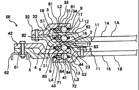
Fig. 1 shows the outlook of a slide device SE. The
slide device SE has two rectangular slide plates 1A, 1B
disposed vertically and parallel with each other. A
rectangular hole 11 for making the slide device SE
lightweight is formed at front and rear positions of a
central part of each of the slide plates 1A, 1B. Both side
parts 12, 13 (only one side part is shown in Fig. 2) of the
lower slide plate 1B and the upper slide plate 1A curve
upward or downward from general parts 14, 15 respectively
and extend horizontally in a constant width. The slide
plates 1A, 1B are formed in the same configuration by press
CA 02460510 2007-03-23
molding and symmetrically disposed at upper and lower
positions by inverting one slide plate. The side part 12 of
the slide plate 1A serves as a rail member L1 which is a
second-type rail member and a movable-side rail member. The
side part 13 of the slide plate 1B constitutes a part of a
rail member L3 which is described later.
A connection plate 2 is fixed to an edge of the
general part 15 of the slide plate 1B. The connection plate
2 extends along left and right edges of the slide plate 1B
(Fig. 1)and as shown in Fig. 2, has a horizontal central
part 21 and side parts 22, 23 curved upward and downward
from the horizontal central part 21 and extending
horizontally in a constant width. The connection plate 2 is
caulked to the slide plate 1B at the side part 23 thereof.
A hold-down plate 3 is caulked to the side part 22 of the
connection plate 2. The hold-down plate 3 extends along the
connection plate 2 (Fig. 1) and has a side part 31 located
at a position upward from a curved portion disposed at its
center and extending horizontally in a constant width and a
side part 32 located at a position downward from the curved
portion and extending horizontally in a constant width. The
hold-down plate 3 and the connection plate 2, more
specifically, the side part 31 of the hold-down plate 3 and
the central part 21 of the connection plate 2 constitute a
rail member L2, which is a first-type rail member and a
fixed-side rail member, forming a U-shaped space S1 open
toward the inner side of the slide device SE and extending
in the longitudinal direction of the rail. The slide plate
1B and the connection plate 2, more specifically, the side
part 13 of the slide plate 1B and the central part 21 of the
connection plate 2 constitute a rail member L3, which is a
first-type rail member and a movable-side rail member,
16
CA 02460510 2007-03-23
forming a U-shaped space open toward the outer side of the
slide device SE and extending in the longitudinal direction
of the rail. These rail members L2, L3 are located at
positions at which the rail members L2 and L3 overlap each
other in the vertical direction.
The rail member L1 which is the side part 12 of the
slide plate lA is located in the U-shaped space of the rail
member L2. A ball 81 serving as a resistance-reducing
member is interposed between an upper surface of the rail
member L1 and a lower surface of the side part 31 of the
hold-down plate 3 opposed to the upper surface of the rail
member L1. A ball 82 serving as a resistance-reducing
member is interposed between a lower surface of the rail
member L1 and an upper surface of the central part 21 of the
connection plate 2 opposed to the lower surface of the rail
member L1. The rail member L1, namely, the slide plate 1A
is slidably movable relative to the rail member L2. That
is, guide grooves 33, 34 parallel with one another
longitudinally and guide grooves 16, 17 parallel with one
another longitudinally and concave in the shape of a
circular arc are formed on the lower surface of the side
part 31 of the hold-down plate 3 and the lower surface of
the rail member L1 respectively. The balls 81 and 82 are
positioned in the guide grooves 33, 34 and the guide grooves
16, 17 respectively. The interval between the adjacent
guide grooves 33 and 34 extending parallel with one another
and the interval between the adjacent guide grooves 16 and
17 extending parallel with one another are so set that the
balls 81, 82 disposed in these guide grooves overlap partly
in the widthwise direction of the rails. That is, the
interval between the centers of the guide grooves 33 and 34
in the widthwise direction thereof is set shorter than the
17
CA 02460510 2007-03-23
total of the radii of the balls 81 disposed in the guide
grooves 33, 34, and the interval between the centers of the
guide grooves 16 and 17 in the widthwise direction thereof
is shorter than the total of the radii of the balls 82
disposed in the guide grooves 16, 17.
The balls 81 and 82 are rotatably held by a ball guide
9. The ball guide 9 is a long plate, formed by molding a
resinous material, having a constant width. A central part
91 (Figs. 4 and 5) in the widthwise direction of the ball
guide 9 is formed thick and both side parts 92 thereof are
formed thin. A large number of ball-holding openings 93, 94
is formed longitudinally in two rows in the central part 91
of a surface of the ball guide 9. The positions of the
ball-holding openings 93 formed in one row and those of the
ball-holding openings 94 formed in the other row are shifted
from each other in the longitudinal direction of the ball
guide 9. More specifically, the ball-holding opening 93 of
the one row is interposed between the ball-holding openings
94 positioned forward and rearward from the ball-holding
opening 93 in the longitudinal direction of the ball guide
9. Further the ball-holding openings 93 and 94 overlap each
other in the longitudinal direction of the ball guide 9.
The ball-holding openings 93 formed in one row and the ball-
holding openings 94 formed in the other row are so formed
that the ball-holding openings 93 and the ball-holding
openings 94 also overlap each other in the widthwise
direction of the ball guide 9 in correspondence to the
positions of the guide grooves 33 and 34.
As shown in Fig. 5, the inner circumference of each of
the ball-holding openings 93, 94 is so formed that the inner
diameter of each of the ball-holding openings 93, 94 is a
little larger than the outer diameter of the balls 81, 82
18
CA 02460510 2007-03-23
and decreases toward the aperture of the ball-holding
openings 93, 94 to make the diameter of the aperture smaller
than the outer diameter of the balls 81, 82. When the balls
81, 82 are inserted into the ball-holding openings 93, 94 by
elastically expanding the aperture of one of the ball-
holding openings 93, 94, the aperture returns to the
original shape and prevents the balls 81, 82 from escaping
from the ball holding openings 93, 94. In this state, as
shown in Fig. 2, the balls 81, 82 are rotatably held in the
ball holding openings 93, 94 with a lower portion of the
balls 81, 82 exposed from the apertures.
In Fig. 2, inside the U-shaped space S2 of the rail
member L3, a rail member L4 which is a second-type rail
member and a fixed-side rail member is disposed. The rail
member L4 is a side part 41 of a guide plate 4 extending
along both sides of the slide plate 1B (Fig. 1). The guide
plate 4 has a side part 42 located at a position upward from
a curved portion disposed at its center and extending
horizontally in a constant width and a side part 41 located
at a position downward from the curved portion and extending
horizontally in a constant width. The guide plate 4 and a
reinforcing plate 5 disposed along the lower surface of the
side part 42, curved, and extended to the lower surface of
the side part 41 are fixed in an inclined posture by a bolt
61 penetrating through the side part 42 to a bracket 62
which is a base member provided on a rotary disk disposed on
a slide mechanism (not shown) disposed in the longitudinal
direction of the vehicle.
A ball 84 is interposed between an upper surface of
the rail member L4 and a lower surface of the central part
21 of the connection plate 2 opposed to the upper surface of
the rail member L4. A ball 82 is interposed between a lower
19
CA 02460510 2007-03-23
surface of the rail member L4 and an upper surface of the
side part 13 of the slide plate 1B opposed to the upper
surface of the side part 13. The rail member L3, namely,
the slide plate 1B is slidably movable relative to the rail
member L4. That is, guide grooves 18, 19; 43, 44; and 71,
72 parallel with one another longitudinally and concave in
the shape of a circular arc are formed on the lower surface
of the central part 21 of the connection plate 2, the upper
surface of the rail member L4, and the upper surface of the
side part 13 of the slide plate 1B respectively. The balls
83, 84 are positioned in the guide grooves 18 through 72.
The interval between the adjacent guide grooves 18 and 19;
43 and 44; and 71 and 72 extending parallel with each other
respectively is so set that the balls 83, 84 disposed in
these guide grooves overlap partly in the widthwise
direction of the rails. That is, the interval between the
centers of the guide grooves 18 and 19; 43 and 44; and 71
and 72 in the widthwise direction thereof is set shorter
than the total of the radii of the balls 83, 84 disposed in
the guide grooves 18 through 72. The balls 83, 84 are
rotatably held by ball guide 9 having the same construction
as that of the ball guide described above. The seat ST
(Fig. 6) is placed on the slide plate 1A.
When the physically handicapped person gets on and off
the vehicle, the entire slide device SE is turned outward
from the vehicle by means of the rotary disk. The slide
plates 1B and lA are slid in an advance direction with the
slide plate 1B disposed froward from the slide plate 1A by
a ball thread driving mechanism as shown in Fig. 3. Then
the seat ST on the slide plate 1A is located at a location
in the vicinity of a road surface.
In the above-described embodiment, the lower-side side
CA 02460510 2007-03-23
wall and the upper-side side wall of each rail member are
formed by molding a material by using the connection plate
common to both the lower-side side wall and the upper-side
side wall. But they may be formed by molding separate
materials. The rail member is formed by molding a material
in integration with the side part of the slide plate, and
the lower-side side wall of the rail member is constructed
of the side part of the slide plate. However, they may be
formed by molding separate materials. In the above-
described embodiment, the fixed-side rail member is
constructed of the first-type rail member, and the movable-
side rail member is constructed of the second-type rail
member. However, the fixed-side rail member may be
constructed of the second-type rail member, and the movable-
side rail member may be constructed of the first-type rail
member.
(Second Embodiment)
In the first embodiment, two slide plates, namely, the
upper and lower slide plates are provided. But three or
more side plates can be provided. Fig. 6 shows a schematic
construction of a slide device having four slide plates. In
Fig. 6, illustration of balls is omitted. In Fig. 6, four
slide plates 1C through 1F are arranged vertically in an
approximately horizontal posture. With the connection plate
2, the hold-down plate 3, and side parts of the slide plates
1C through iF, rail members L6 through L11 forming U-shaped
spaces open toward the inner and outer sides of the slide
device SE are formed. These members are so disposed that
they overlap each other in the vertical direction. In the
rail members L7 through L10, an upper side 30 and a lower
side 10 of one rail member penetrate into the U-shaped space
of the other rail member. The upper sides 30 and the lower
21
CA 02460510 2007-03-23
sides 10 constitute second-type rail members. The rail
members L8, L10, provided on the slide plates 1E, 1F
respectively, serving as a fixed-side rail member support
the lower side 10 of the rail members L7, L9 provided on the
slide plates 1D, 1E respectively as a movable-side rail
member which is slidably movable. The rail member L5, which
is a side part 20 of the uppermost slide plate 1C, serving
as a second-type rail member and the movable-side rail
member penetrates into the U-shaped space of the rail member
L6, serving as the first-type rail member and the fixed-side
rail member, provided on the slide plate 1D and is slidably
supported by the rail member L6. A rail member L12, which
is a side part 41 of the guide plate 4, serving as the
second-type rail member and the fixed-side rail member
penetrates into the U-shaped space of the rail member L11,
serving as the first-type rail member and the fixed-side
rail member, provided on the slide plate 1F positioned
lowermost and is slidably supported by the rail member L11.
(Third Embodiment)
Fig. 7 shows a sectional view of main parts of a slide
device. In Fig. 7, a fixed-side rail member (only one
fixed-side rail member is shown) 60 of the slide device is
constructed by connecting an upper rail 601 and a lower rail
602 to each other. That is, a long plate is formed by press
molding to form the upper rail 601 and the lower rail 602.
Half parts 6012 and 6022 extending approximately
horizontally are bent vertically upward and downward from
half parts 6011 and 6021 respectively at approximately the
center of the upper rail 601 and the lower rail 602 in the
widthwise direction of the rail. Thus the upper rail 601
and the lower rail 602 have the same configuration in
section. The half parts 6011 and 6021 are butted against
22
CA 02460510 2007-03-23
each other with the half parts 6011 and 6021 located
symmetrically and vertically. The half parts 6011 and 6021
are fixedly connected to a bracket M2 on a floor F with a
bolt Ml penetrating through the half parts 6011 and 6021
vertically. On an opposed surface of the half part 6012 of
the upper rail 601 and an opposed surface of the lower rail
602 vertically opposed to the upper rail 601 at a certain
interval, a pair of guide grooves 603, 604 and a pair of
grooves 605, 606 concave in the shape of a circular arc are
formed respectively. A pair of the guide grooves 603, 604
and a pair of the grooves 605, 606 extend parallel with each
other respectively in the longitudinal direction of the
rails.
The half parts 6012, 6022 located vertically and bent
parts 6013, 6023 located vertically form a U-shaped space
open sideways. A movable-side rail 701 is positioned in the
U-shaped space. In this embodiment, the movable-side rail
701 is formed on a side edge of the slide plate 70 as a part
thereof. That is, the slide plate 70 is bent downward at
its both side edges (only one side is shown in Fig. 7) by
press molding to form the side edges as the movable-side
rail 701. A pair of guide grooves 702, 703 adjacent to each
other, extending parallel with each other in the
longitudinal direction of the rail, and concave in the shape
of a circular arc are formed on the upper surface of the
movable-side rail 701 at positions thereof opposed to the
guide grooves 603, 604 of the upper rail 60. The balls 81
are interposed between the guide grooves 702, 703 formed on
the upper surface of the movable-side rail 701 and the guide
grooves 603, 604 of the upper rail 601. The balls 82 are
interposed between the lower surface of the movable-side
rail 701 and the guide grooves 605, 606 of the lower rail
23
CA 02460510 2007-03-23
602. The movable-side rail 701 is vertically sandwiched
between the upper rail 601 and the lower rail 602 through
the balls 81, 82 and is slidable. The interval between the
adjacent guide grooves 603 and 604; 605 and 606; and 702 and
703 respectively is so set that the balls 81, 82 disposed in
these guide grooves overlap in the widthwise direction of
the rails. That is, the interval between the centers of the
guide grooves 603 and 604; 605 and 606; and 702 and 703 in
the widthwise direction thereof is set shorter than the
total of the radii of the balls 81, 82 disposed in the guide
grooves 603, 604, 605, 606, 702, and 703. The movable-side
rail formed at the other side edge of the slide plate 70 has
a construction similar to the above-described one and is
slidably sandwiched between the upper and lower rails of the
fixed-side rail through the balls. A rotary disk
constructed of an inner ring and an outer ring is provided
on the slide plate 70 at a position thereof situated between
the widthwise center thereof and one side edge. Teeth
formed on the entire periphery of the outer ring serving as
a movable ring is in engagement with teeth of a rack formed
on the fixed-side rail 60. A plate-shaped seat-installing
bracket is placed on the outer ring, and a seat is provided
on the bracket. The balls 81, 82 disposed on and under the
movable-side rail 701 are rotatably held by the ball guide
9 similar to that described in the first embodiment. The
ball guide 9 is a long plate, formed by molding a resinous
material, having a constant width. A central part 91 in the
widthwise direction of the ball guide 9 is formed thick and
both side parts 92 thereof are formed thin. A large number
of ball-holding openings 93, 94 is formed longitudinally in
two rows in the central part 91 of a surface of the ball
guide 9. The positions of the ball-holding openings 93
24
CA 02460510 2007-03-23
formed in one row and those of the ball-holding openings 94
formed in the other row are shifted from each other in the
longitudinal direction of the ball guide 9. More
specifically, the ball-holding opening 93 of the one row is
interposed between the ball-holding openings 94 positioned
forward and rearward from the ball-holding opening 93 in the
longitudinal direction of the ball guide 9. Further the
ball-holding openings 93 and 94 overlap each other in the
longitudinal direction of the ball guide 9. The ball-
holding openings 93 formed in the one row and the ball-
holding openings 94 formed in the other row are so formed
that the ball-holding openings 93 and the ball-holding
openings 94 also overlap each other in the widthwise
direction of the ball guide 9 in correspondence to the
positions of the guide grooves 603, 604, 605, 606, 702, and
703.
The inner circumference of each of the ball-holding
openings 93, 94 is so formed that the inner diameter of each
of the ball-holding openings 93, 94 is a little larger than
the outer diameter of the balls 81, 82 and decreases toward
the aperture of the ball-holding openings 93, 94 to make the
diameter of the aperture smaller than the outer diameter of
the balls 81, 82. When the balls 81, 82 are inserted into
the ball-holding openings 93, 94 by elastically expanding
the aperture of one of the ball-holding openings 93, 94, the
aperture returns to the original shape and prevents the
balls 81, 82 from escaping from the ball holding openings
93, 94. In this state, as shown in Fig. 7, the balls 81, 82
are rotatably held in the ball holding openings 93, 94 with
a lower portion of the balls 81, 82 exposed from the
apertures.
In the slide device of this embodiment, it is possible
CA 02460510 2007-03-23
to make the number of balls two times that of the
conventional slide device, although the length of the ball
guide 9 is equal to that of the conventional slide device.
Thus when a high load of vertically shifting the fixed-side
rail 60 and the movable-side rail 701 relative to each other
is applied, the load is dispersed to a large number of the
balls 81, 82 and hence the surface pressure of each of the
balls 81, 82 is reduced to about 1/2 of that applied to the
surface pressure of the ball in the conventional slide
device. Therefore it is unnecessary to quench the guide
grooves 603, 604, 605, 606, 702, and 703 and it is possible
to save labor required in manufacturing the slide device and
reduce the manufacturing cost. In this embodiment, the
movable-side rail 701 is vertically sandwiched between the
upper rail 601 and the lower rail 602 disposed through the
balls 81, 82. Therefore the slide device has a sufficient
degree of durability when a load of vertically shifting the
rails 601, 602 is applied. Because the upper rail 601 and
the lower rail 602 constituting the fixed-side rail 60 and
the movable-side rail 701 can be all manufactured by press
molding, it is possible to reduce the manufacturing cost.
In addition, the adjacent guide grooves 603, 604, 605, 606,
702, and 703 are spaced from each other in such a way that
the balls 81, 82 disposed in these grooves overlap each
other in the longitudinal direction of the rails. Therefore
it is possible to minimize the guide groove formation range
in the widthwise direction (right-to-left direction in Fig.
7) on the lower surface of the upper rail 60, the opposed
upper surface of the lower rail 602, and the upper and lower
surfaces of the movable-side rail 701. Thereby it is
possible to make the movable-side rails compact.
In the above-described embodiment, the guide grooves
26
CA 02460510 2007-03-23
formed on the lower and upper rails and on the movable-side
rail are formed in two parallel rows. But three or more
rows may be formed. In the above-described embodiment, the
guide groove is formed on only the upper surface of the
movable-side rail. But it is possible to form the guide
groove on the lower surface of the movable-side rail in
confrontation with the guide groove of the lower rail. In
the above-described embodiment, the movable-side rail is
formed at a portion of the slide plate. But this may be
molded separately. In this case, by forming the movable-
side rail, the upper rail, and the lower rail in the same
shape, it is possible to reduce the manufacturing cost.
Further instead of adopting the construction of sandwiching
the movable-side rail between the upper and lower rails
through the balls, the present invention is applicable to a
construction of interposing the balls between the side
surface of the fixing-side rail and the opposed side surface
of the movable-side rail. In addition, the slide device of
the present invention is applicable to other uses than the
slide seat mechanism. The ball guide does not necessarily
have to have the construction described in the above
embodiment. But it is possible to use the ball guide
capable of holding the balls in the disposition state
described in the above embodiment. But it is essential to
dispose the balls in a such a manner that balls positioned
forward and rearward overlap each other in the widthwise
direction normal to the guide groove formation direction.
INDUSTRIAL APPLICABILITY
As described above, the slide device of the present
invention can be easily manufactured and assembled and is
applicable to the slide seat which is used when the
physically handicapped person gets and on the vehicle.
27