Language selection

Search

Patent 2460555 Summary

Third-party information liability

Some of the information on this Web page has been provided by external sources. The Government of Canada is not responsible for the accuracy, reliability or currency of the information supplied by external sources. Users wishing to rely upon this information should consult directly with the source of the information. Content provided by external sources is not subject to official languages, privacy and accessibility requirements.

Claims and Abstract availability

Any discrepancies in the text and image of the Claims and Abstract are due to differing posting times. Text of the Claims and Abstract are posted:

  • At the time the application is open to public inspection;
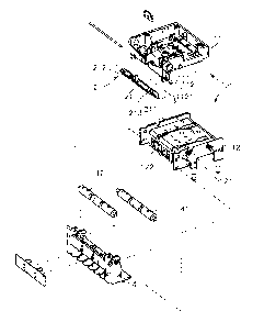
  • At the time of issue of the patent (grant).
(12) Patent Application: (11) CA 2460555
(54) English Title: AUTO-BILL-DISPENSING MACHINE
(54) French Title: DISTRIBUTRICE A BILLETS AUTOMATIQUE
Status: Deemed Abandoned and Beyond the Period of Reinstatement - Pending Response to Notice of Disregarded Communication
Bibliographic Data
(51) International Patent Classification (IPC):
  • G07F 09/00 (2006.01)
  • G07B 03/00 (2006.01)
  • G07F 07/10 (2006.01)
  • G07F 19/00 (2006.01)
  • G07G 05/00 (2006.01)
(72) Inventors :
  • YANG, YA-HUI (Taiwan, Province of China)
  • LIN, YI-CHIA (Taiwan, Province of China)
(73) Owners :
  • INTERNATIONAL CURRENCY TECHNOLOGIES CORPORATION
(71) Applicants :
  • INTERNATIONAL CURRENCY TECHNOLOGIES CORPORATION (Taiwan, Province of China)
(74) Agent: SMART & BIGGAR LP
(74) Associate agent:
(45) Issued:
(22) Filed Date: 2004-03-10
(41) Open to Public Inspection: 2004-09-28
Availability of licence: N/A
Dedicated to the Public: N/A
(25) Language of filing: English

Patent Cooperation Treaty (PCT): No

(30) Application Priority Data:
Application No. Country/Territory Date
092204897 (Taiwan, Province of China) 2003-03-28

Abstracts

English Abstract


An auto-bill-dispensing machine is provided. The auto-bill-dispensing machine
comprises bill receiver having a plurality of security hooks positioned
axially between
two positioning plates formed on the two sides of the upper chassis of the
bill receiver,
and the security hooks are against within a plurality of blocking grooves of
the lower
chassis to block the bill passage. When the bill enters into the bill passage
and being held
against on the security hooks, the security hooks of the bill receiver will be
out of the
blocking groove of the lower chassis to let the bill pass through, and after
the bill passes
the security hooks, the security device will return to the original position
to make the
security hooks support within the blocking groove of the lower chassis to
prevent the bill
being pulled back by a string, a tape, a steel wire or a glued metallic plate.


Claims

Note: Claims are shown in the official language in which they were submitted.

WHAT THE INVENTION CLAIMED IS
1. An auto-bill-dispensing machine comprising:
a bill receiver comprising an upper chassis and a lower chassis, wherein
between
said upper chassis and lower chassis forms a bill passage, at the frontal
flange on each
side of said upper chassis forms a positioning element and a plurality of
blocking groove
is positioned at a central region of said lower chassis; and
a security device positioned axially within the bill receiver, wherein said
security
device comprises a base, wherein said base is movable in between the two sides
of said
upper chassis and said positioning element, and a plurality of security hooks
is formed at
the bottom flange of said base, said security hooks are movable and support
onto said a
plurality of blocking groove of lower chassis to block said bill passage.
2. The auto-bill-dispensing machine according to claim l, wherein said
positioning element of upper chassis has a through hole, and on the two sides
of said base
of security device has through holes so that said positioning element and said
base can be
assembled together by using an axle element to penetrate through said through
hole of
said positioning element and said through holes of said base.
3. The auto-bill-dispensing machine according to claim l, wherein said base of
the security device has a weight block on a top face.
4. The auto-bill-dispensing machine according to claim 1, wherein said
security
hook of the security device is in an arched pointed shape.
5. The auto-bill-dispensing machine according to claim 1, wherein said lower
chassis of bill receiver comprises a roller holder, and on said roller holder
has a first
roller set and a second roller set.
7

6. The auto-bill-dispensing machine according to claim l, wherein said first
roller
set and second roller set are supported an each other.
7. The auto-bill-dispensing machine according to claim l, wherein said first
roller
set and second roller set are made of a rubber material.
8. The auto-bill-dispensing machine according to claim l, wherein on each side
of
said upper chassis has a protrusion, on each corresponding side of said lower
chassis has
a fitting groove so that said protrusions of the upper chassis can fit into
said fitting
grooves of the lower chassis for positioning.
8

Description

Note: Descriptions are shown in the official language in which they were submitted.


CA 02460555 2004-03-10
AUTO-BILL-DISPENSING MACHINE
BACKGROUND OF THE INVENTION
I . The field of the invention
[OOOI] The present invention relates to an auto-bill-dispensing machine, and
more
S particularly relates to a bill receiver of a auto-bill-dispensing machine
comprising a
plurality of security hooks positioned axially between two positioning plates
formed on
the two sides of an upper chassis of the bill receiver, and the security hooks
are
positioned within and against a plurality of blocking grooves of the lower
chassis to block
the bill passage.
2. Description of the related art
[0002] With the rapid advancement and development in electronic industry, the
auto-bill-dispensing machines (such as card dispensing machine, ticketing
machine or
auto-changing machine) are installed in many public places far satisfying the
requirement
of the consumers as convenience and prompt service. The service provided by
these
machines are not only for substantially reducing the labor cost but also more
acceptable
to the consumers for the convenience provided. However, the general automatic
vending
machines will be under the supervision only in the routine manual storage
check-up or
maintenance, and when they are not under the supervision by the authorized
party, the
cards or bills therein can be stolen by using several methods. Referring to
the vending
machine of a prior art as shown in Fig. 6, which indicates that the
conventional bill
receiver comprises a frame A, on a side of the frame A has a receiving slot A1
for
receiving bills, and on the upper and lower side of the bill passage
positioned inside of
the frame A fixed with a circuit board B for identifying the bills and a motor
device C.
1

CA 02460555 2004-03-10
Further, at the exit A2 positioned with a security plate D for preventing the
bill being
pulled out after accepting by the bill receiver A1. As bill is made of soft
material and
gets damage when being pulled by force, such destructive activity can also
break down
the operation of the bill receiver. And if a thief uses a harder material, for
example, steel
wire, metallic plate or alike, to try to pull out the bill, the security
device of the
conventional is incapable of preventing the bills from being stolen.
According, it is
highly desirable to improve the structure of the bill receiver to overcome the
defects of
the prior art.
SUm~rIARY OF THE INVENTION
[0003] Accordingly, in the view of the foregoing, the present inventor makes a
detailed study of related art to evaluate and consider, and uses years of
accumulated
experience in this field, and through several experiments, to create a new
structure of a
bill receiver for an auto-bill- dispensing machine in order to improve the
security of the
auto-bill-dispensing machine to effectively prevent the bills from being
stolen.
[0004] According to one aspect of the present invention, a bill receiver
comprising
a plurality of security hooks positioned axially between two positioning
plates formed on
the two sides of the upper chassis of the bill receiver is provided, and the
security hooks
are positioned within and against a plurality of blocking grooves of the lower
chassis to
block the bill passage.
[0005]According to another aspect of the present invention, when the bill
enters
into the bill passage and is being held against the security hooks, the
security hooks of the
security device will be out of the blocking groove of the lower chassis to let
the bill pass
through, and after the bill passes the security hooks, the security device
will return to the
2

CA 02460555 2004-03-10
original position to make the security hooks support within the blocking
groove the lower
chassis, and thus preventing the bill from being pulled back by using a
string, a tape, a
steel wire or a glued metallic plate adhering onto the bill.
BRIEF DESCRIPTION OF THE DRAWINCr
[0006] For a more complete understanding of the present invention, reference
will
now be made to the following detailed description of preferred embodiments
taken in
conjunction with the accompanying drawings, in which:
[0007] Fig. 1 is an elevational view of an auto-bill-dispensing machine of the
present invention;
[0008]Fig. 2 is an exploded view of the auto-bill-dispensing machine of the
present invention;
[0009]Fig. 3 is a sectional view showing before the bill enters to the bill
receiver
of the present invention;
[0010]Fig. 4 is a sectional view showing when the bill enters into the bill
receiver
of the present invention;
[0011]Fig. 5 is a sectional view showing after the bill enters to the bill
receiver of
the present invention; and
[0012]Fig. 6 is a sectional view of a conventional auto-bill-dispensing
machine.
DETAILED DESCRIPTION OF PREFERRED EMBODIMENTS
[0013] Reference will be made in detail to the preferred embodiments of the
invention, examples of which are illustrated in the accompanying drawings.
Wherever
possible, the same reference numbers are used in the drawings and the
description to refer
to the same or Like parts.
3

CA 02460555 2004-03-10
[0014] Referring to Figs. l, 2 and 3, the auto-bill-dispensing machine of the
present invention comprises a bill receiver 1 and a security device 2
positioned axially
within the bill receiver 1. The bill receiver 1 comprises an upper chassis 11
and a lower
chassis 12, and on each side of the upper chassis 11 comprises a protrusion
111, and on
each corresponding side of the lower chassis 12 comprises a fitting groove
121, thus the
protrusions 111 of the upper chassis 11 can fit into the fitting groove 121 of
the lower
chassis 12 forming a bill passage 13 in between the upper chassis 11 and the
lower
chassis 12. Further, at the frontal flange of each side of the upper chassis
11 extends into
a positioning element 112 having a through hole 1121, and a plurality of
blocking
grooves 122 is formed at the central region of the lower chassis 12.
[0015]The security device 2 comprises a base 21, and at the bottom flange of
the
base 21 has a plurality of arched pointed security hooks 211. Further; on a
top face of the
base 21 comprises a projected weight block 212, and a plurality of through
holes 213 is
formed on the two sides of the base 21.
[0016]The feature provided by the above described embodiment is to fix the
security device 2 between the positioning elements 112 on the two sides of the
upper
chassis 11, and by using an axle element 3 to penetrate through the through
hole 1121 of
the positioning element 112 and the through hole 213 of the base 21 to further
position
the security device 2, thus the security device 2 is able to rotate at an
angle by using the
axle element 3 as an axis.
[0017]Furthermore, the lower chassis 12 of the bill receiver 1 comprises a
roller
holder 4, and a first roller set 41 and a second roller set 42 are positioned
on a top of the
roller holder 4 axially positioned, and the first roller set 41 and the second
roller set 42 on
4

CA 02460555 2004-03-10
the roller holder 4 are supported against each other and are positioned at the
exit of the
bill passage 13.
[0018]Referring to Figs. 3, 4 and 5, the actual operation of the bill receiver
of the
present invention is described. Before operating the bill receiver l, the
security hooks
211 of the security device 2 are supported onto the blocking groove 122 of the
lower
chassis 12 by the weight of the weight black 212, and also block in the bill
passage 13 is
positioned closing the bill passage 13. When the bill 5 enters into the bill
passage 13 of
the bill receiver 1, the frontal edge of the bill 5 is against and pushes the
arched side of
the security hooks 211 allowing the security hook 211 to rotate at an angle
and further to
release itself from the blocking groove 122 of the lower chassis 12, thus a
slit is created
in the bill passage 13 to let the bill S pass through. If a thief tries to use
a string, a tape, a
steel wire, a glued metallic plate or alike for attempting to steal the bill
5, the security
hooks 211 will effectively blocks the bill 5 from being removed by the above
mentioned
string, tape, steel wire, glued metallic plate or alike. And after the bill 5
passes through
the slit successfully, the security hooks 211 will return to the original
position
automatically under the influence of gravity due to the weight of the weight
block 212
and is supported by the blocking groove 122 of the lower chassis 12 and also
blocks the
bill passage 13 to close the bill passage 13, and therefore, the bill 5 is
effectively
prevented from being stolen by using a string, a tape, a steel wire, or a
glued metallic
plate or alike.
[0019] While the invention has been described in conjunction with a specific
best
mode, it is to be understood that many alternatives, modifications, and
variations will be
apparent to those skilled in the art in light of the foregoing description.
Accordingly, it is
5

CA 02460555 2004-03-10
intended to embrace all such alternatives, modifications, and variations in
which fall
within the spirit and scope of the included claims. All matters set forth
herein or shown in
the accompanying drawings are to be interpreted in an illustrative and non-
limiting sense.
6

Representative Drawing
A single figure which represents the drawing illustrating the invention.
Administrative Status

2024-08-01:As part of the Next Generation Patents (NGP) transition, the Canadian Patents Database (CPD) now contains a more detailed Event History, which replicates the Event Log of our new back-office solution.

Please note that "Inactive:" events refers to events no longer in use in our new back-office solution.

For a clearer understanding of the status of the application/patent presented on this page, the site Disclaimer , as well as the definitions for Patent , Event History , Maintenance Fee  and Payment History  should be consulted.

Event History

Description Date
Inactive: IPC expired 2019-01-01
Application Not Reinstated by Deadline 2010-03-10
Time Limit for Reversal Expired 2010-03-10
Deemed Abandoned - Failure to Respond to Maintenance Fee Notice 2009-03-10
Inactive: IPC from MCD 2006-03-12
Application Published (Open to Public Inspection) 2004-09-28
Inactive: Cover page published 2004-09-27
Inactive: <RFE date> RFE removed 2004-08-18
Inactive: Adhoc Request Documented 2004-08-17
Amendment Received - Voluntary Amendment 2004-07-23
Request for Examination Received 2004-07-23
Inactive: First IPC assigned 2004-05-18
Inactive: IPC assigned 2004-05-18
Inactive: Filing certificate - No RFE (English) 2004-04-15
Letter Sent 2004-04-15
Application Received - Regular National 2004-04-15

Abandonment History

Abandonment Date Reason Reinstatement Date
2009-03-10

Maintenance Fee

The last payment was received on 2008-02-26

Note : If the full payment has not been received on or before the date indicated, a further fee may be required which may be one of the following

  • the reinstatement fee;
  • the late payment fee; or
  • additional fee to reverse deemed expiry.

Patent fees are adjusted on the 1st of January every year. The amounts above are the current amounts if received by December 31 of the current year.
Please refer to the CIPO Patent Fees web page to see all current fee amounts.

Fee History

Fee Type Anniversary Year Due Date Paid Date
Application fee - standard 2004-03-10
Registration of a document 2004-03-10
MF (application, 2nd anniv.) - standard 02 2006-03-10 2006-02-14
MF (application, 3rd anniv.) - standard 03 2007-03-12 2007-01-30
MF (application, 4th anniv.) - standard 04 2008-03-10 2008-02-26
Owners on Record

Note: Records showing the ownership history in alphabetical order.

Current Owners on Record
INTERNATIONAL CURRENCY TECHNOLOGIES CORPORATION
Past Owners on Record
YA-HUI YANG
YI-CHIA LIN
Past Owners that do not appear in the "Owners on Record" listing will appear in other documentation within the application.
Documents

To view selected files, please enter reCAPTCHA code :


To view images, click a link in the Document Description column. To download the documents, select one or more checkboxes in the first column and then click the "Download Selected in PDF format (Zip Archive)" or the "Download Selected as Single PDF" button.

List of published and non-published patent-specific documents on the CPD .

If you have any difficulty accessing content, you can call the Client Service Centre at 1-866-997-1936 or send them an e-mail at CIPO Client Service Centre.


Document
Description 
Date
(yyyy-mm-dd) 
Number of pages   Size of Image (KB) 
Description 2004-03-09 6 261
Abstract 2004-03-09 1 28
Claims 2004-03-09 2 75
Drawings 2004-03-09 6 161
Representative drawing 2004-07-21 1 13
Courtesy - Certificate of registration (related document(s)) 2004-04-14 1 105
Filing Certificate (English) 2004-04-14 1 158
Reminder of maintenance fee due 2005-11-13 1 109
Courtesy - Abandonment Letter (Maintenance Fee) 2009-05-04 1 172
Fees 2006-02-13 1 27
Fees 2007-01-29 1 28
Fees 2008-02-25 1 36